Cisco Catalyst 8500 Series Edge Platforms Architecture White Paper
Available Languages
Bias-Free Language
The documentation set for this product strives to use bias-free language. For the purposes of this documentation set, bias-free is defined as language that does not imply discrimination based on age, disability, gender, racial identity, ethnic identity, sexual orientation, socioeconomic status, and intersectionality. Exceptions may be present in the documentation due to language that is hardcoded in the user interfaces of the product software, language used based on RFP documentation, or language that is used by a referenced third-party product. Learn more about how Cisco is using Inclusive Language.
Cisco launched the all-new Cisco® Catalyst® 8500 Series Edge Platforms in late 2020. These platforms are highly capable and purpose-built to address traditional WAN, emerging SD-WAN and colocation use cases. This white paper takes a deep dive into the Catalyst 8500 platform’s architecture and key building blocks. Awareness of the platform architecture will enable you to design best-in-class networks that incorporate it.
Introduction to the Catalyst 8500 Series
The Cisco Catalyst 8500 Series Edge Platforms are fixed form factor, 1 rack-unit aggregation platforms. Two models are available:
● C8500-12X4QC
● C8500-12X
The platforms are equipped with a built-in route processor, an embedded services processor and interface connectivity using Ethernet ports.
The Catalyst 8500 Series hosts the innovative third-generation Cisco QuantumFlow Processor™ (QFP) 3.0 Application-Specific Integrated Circuit (ASIC). The QFP 3.0 enhances the hardware-based forwarding, bringing it to a whole new level. Along with embedded services applications and high-speed forwarding, the QFP 3.0 also hosts integrated Layer 2 subsystem and IPsec crypto functionality within the same ASIC.
The Catalyst 8500 Series platforms include the following components:
● Built-in route processor
● Built-in embedded services processor
● Built-in aggregation hardware for different types of interfaces and connectivity
● Redundant AC or DC power supplies
● Removable fan assembly
● On/off switches on the power supplies (AC and DC)
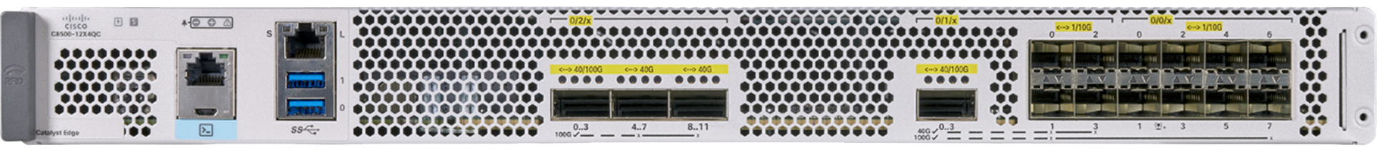
C8500-12X4QC model
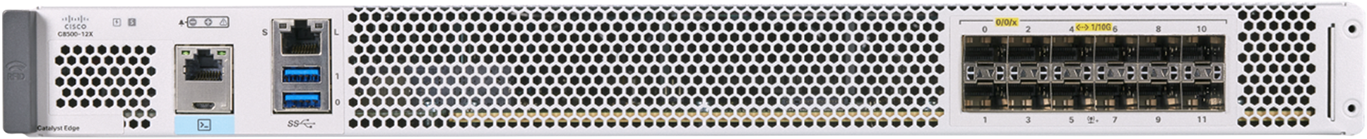
C8500-12X model
To understand the Catalyst 8500 Series, you need to understand the key building blocks. The most important of these is the QFP 3.0, which enables the platform’s powerful data plane.
The Catalyst 8500 Series continues the innovations of the Cisco QuantumFlow Processor, which made the Cisco ASR 1000 Series platform so successful. The Cisco QuantumFlow Processor constitutes the entire forwarding engine of the system and has been designed with five goals in mind: scale, performance, feature velocity, versatility and multigenerational capability.
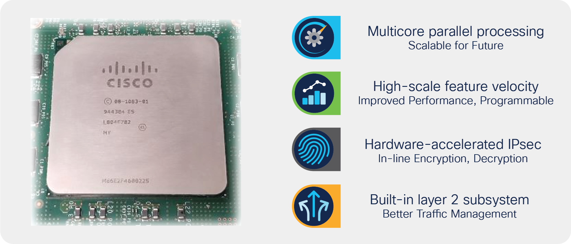
The Cisco QuantumFlow Processor
The Cisco QFP converges three principal components:
Packet Processing Engine (PPE): The QFP 3.0 consolidates 224 customized PPEs into a single piece of silicon. This massive amount of parallel processing reduces any requirements for external service blades inside the router.
Each PPE is a 32-bit Reduced Instruction Set Computer (RISC) core. Each PPE can process four threads, which corresponds to the ability to process four packets independently and in parallel. In other words, the QFP 3.0 implements a potential well of 224 x 4, or 896 separate packet-processing resources.
The software model used in packet processing allows for each PPE thread to process a packet independently and does not enforce a tight coupling between processing packets and the use of resources inside the chip. As a thread waits for various hardware assists, the PPE can work on the other three threads and help ensure that PPE processor usage always stays optimal and latencies for packet processing remain low.
A distributor function assigns one of the threads of the PPE to a particular context (or packet). The assigned PPE is responsible for the packet for its entire life in on-chip memory before it is sent to the traffic manager for scheduling.
Each PPE has access to an array of hardware-assist functions such as Layer 1 and Layer 2 cache or Ternary Content-Addressable Memory (TCAM) for feature acceleration of network address and prefix lookups, hash lookups, Weighted Random Early Detection (WRED), traffic policers, range lookups, advanced classification, and Access Control Lists (ACLs). In flow-control situations, a lock manager assures the proper packet ordering for flows.
Another key resource for the Cisco QFP 3.0 ASIC is the cryptographic engine, which is accessible from each PPE.
Buffering, Queuing, Scheduling (BQS): A dedicated flexible-queuing engine offers a dramatic offload of buffering, queuing, and scheduling processing to address today’s very complex subscriber and interface-level queuing requirements of both enterprise and carrier networks.
When packet processing is completed, the PPE thread releases the packet to the traffic manager. It is here that any operations related to actual queue scheduling occur.
The traffic manager implements advanced real-time flexible queuing hardware with 256,000 queues and the ability to set three parameters for each queue for maximum bandwidth, minimum bandwidth, and excess bandwidth.
In addition, two priority queues can be enabled for each Quality-of-Service (QoS) policy applied. The traffic manager can schedule multiple levels of hierarchy in one pass through the chip with priority propagation through the hierarchy.
External resources such as cryptographic devices and route processors are also scheduled appropriately on the Cisco QFP such that they are never overwhelmed.
Highly programmable forwarding: The software architecture is based on a full ANSI-C development environment implemented in a true parallel processing environment. It allows new features to be added quickly as customer requirements evolve by taking advantage of industry-standard tools and languages. And it is built upon a powerful parallel processing architecture. This architecture represents a paradigm shift and evolution in the software architectures associated with network processing today.
The Catalyst 8500 Series platforms host the QFP 3.0 ASIC as the main data path component. It is capable of applying complex services at the hardware level of forwarding. The QFP 3.0 also hosts Layer 2 subsystem and crypto ciphers within the ASIC.
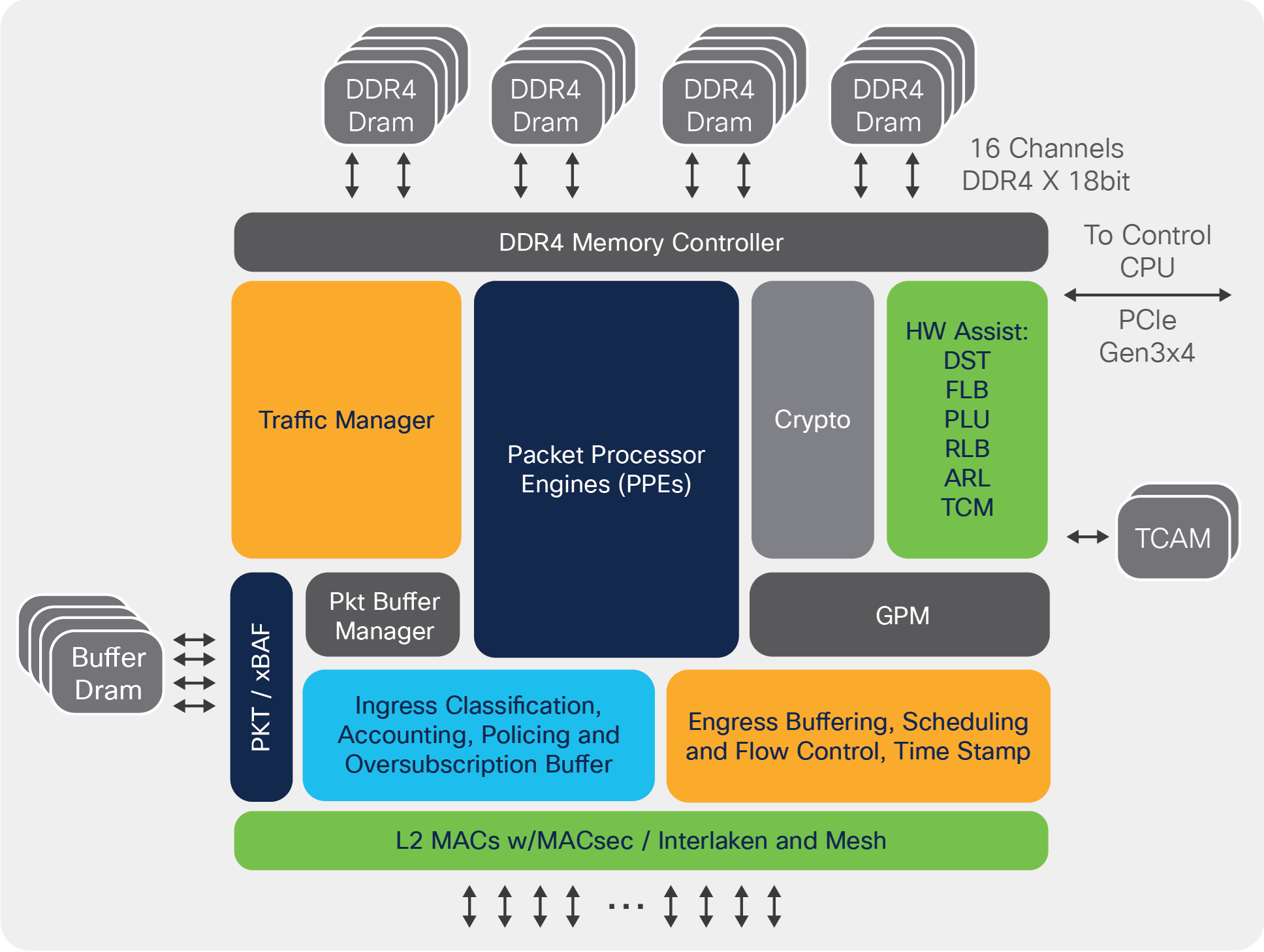
QuantumFlow Processor 3.0 block diagram
Highlights of the QFP 3.0
● Up to twice the processing power of the QFP 2.0 ASIC
● Unified architecture NPU that supports all existing feature code
● System On a Chip (SoC): Approximately twice the improvements in watts per Mpps compared to the QFP 2.0
● Integrated classification-based Layer 2 subsystem: Integrated 1/10/40/100 Gigabit Ethernet (GE) MACs
● Virtual single NPU complex via mesh interconnect: Support for single use as well as 2x and 4x ASIC meshes
● Embedded security and crypto: Crypto engines are embedded in the ASIC, with dedicated cores for IPsec
● 16 crypto engines: Each crypto engine contains packet input buffer, cipher, digest, and checksum engines; each cipher and digest engine has all the logic necessary to execute any of the supported underlying cipher algorithms
● Acceleration infrastructure for complex features and flow handling: 50% more instructions available per packet for feature processing and high-performance DDR4 resource memory subsystem (16 channels)
● Improved classification and QoS: Modular QoS CLI (MQC) compliant hardware traffic management with 256,000 queues, EtherChannel support (200 Gbps max single bundle bandwidth), distributed traffic management with improved granularity
● Integrated support for 240 Gbps of aggregate Ethernet ports (2x 120 Gbps)
● Supports full per-port, Layer 2/3, TCAM-based classification
● Supports Rx sub-interface and MAC classification and accounting: 4000 Rx VLANs, 8000 Hot Standby Router Protocol (HSRP) destination addresses, 512 EtherTypes
● Supports Tx sub-interface and MAC accounting
● Line-rate WAN MACsec for 240 Gbps of Ethernet interfaces
● ASIC targets much higher throughput of combined cipher + digest at IMIX packet sizes
The Catalyst 8500 Series platforms have a built-in control plane to establish route processor functionalities.
The control plane implementation is responsible for the following functions:
● Running the router control plane, including network control packets and connection setup
● Synchronizing the active and standby processes in dual Cisco IOS® redundancy operation
● Code storage, management, and upgrades
● Onboard Failure Logging (OBFL)
● Downloading operational code for interface control blocks and forwarding processor, QFP over Ethernet Out-of-Band Channel (EOBC), which is used for communication between the control processors on the 8500 Series
● The command-Line Interface (CLI), alarm, network management, logging, and statistics aggregation
● Punt path processing of packets not supported by the embedded services processors
● A configuration repository for logging system statistics, records, events, errors, and dumps of the management interfaces of the platform, including the console serial port
● The MGMT Ethernet (ENET) management ports, CLI, status indicators, USB ports for secure key distribution, and a micro-USB console
● The field-replaceable fan tray, power supply module, Online Insertion and Removal (OIR) events, etc.
● The chassis management, including activation and initialization of the other cards, selection or switchover of active versus standby cards, image management and distribution, logging facilities, distribution of user configuration information, and alarm control
● The control signals for monitoring the health of power entry modules, shutting down the power, and driving alarm relays located on the power entry modules
● One core from the quad-core CPU is also available for edge-compute services using the Cisco IOx application hosting infrastructure
Let’s look at how the building blocks are bound together to construct the C8500-12X4QC edge platform.
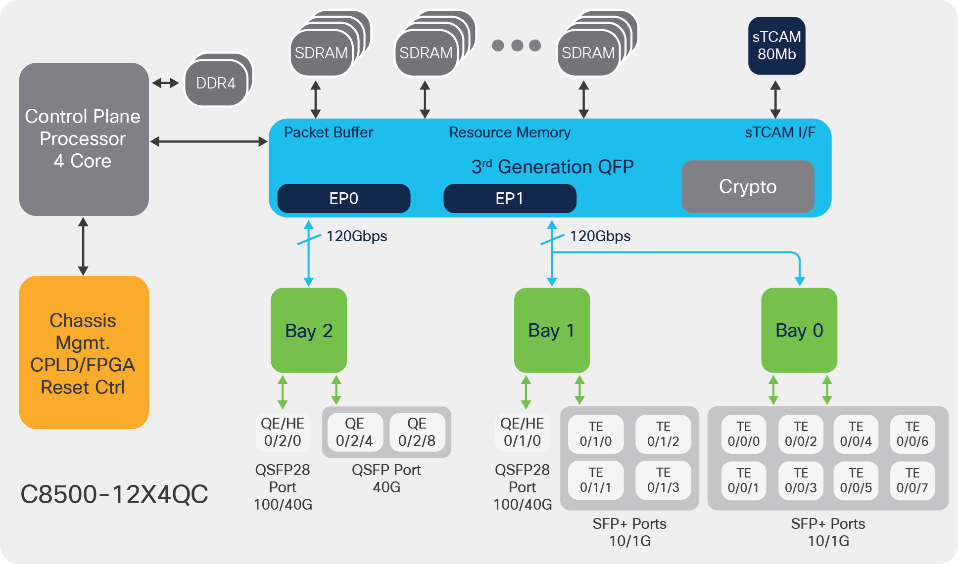
C8500-12X4QC block diagram
The important hardware entities within the system are:
● Control Plane Processor (CPP): A quad-core x86 processor that runs the Cisco IOS daemon (IOSd) and other required system processes.
● QFP 3.0: Cisco’s innovative data path ASIC with 10+ years of innovation, capable of applying complex services at the hardware level of forwarding. The QFP 3.0 ASIC also hosts Layer 2 subsystem and crypto ciphers.
● EP0 and EP1: Two Layer 2 aggregation points within the QFP that help with input/output traffic handling via the bay 0, 1, and 2 Ethernet interfaces.
● Bay 0 and bay 1 together these serve 120 Gbps of aggregation capacity via EP1, and bay 2 serves 120 Gbps of aggregation capacity via EP0 orchestration.
● The CPP and QFP are accompanied by enough packet buffer and resource memory to be able to serve highly complex services application at augmented traffic rates.
● The C8500-12X4QC edge platform comes with 80 Mb of TCAM space, which helps achieve the fastest classification operations for features such as ACLs and access control entries (ACEs), QoS classifications, Policy-Based Routing (PBR) route maps, etc.
● The chassis management block helps manage the overall chassis hardware components and their interrupts for smooth operation of the platform.
The following figure shows the block diagram for the C8500-12X edge platform.
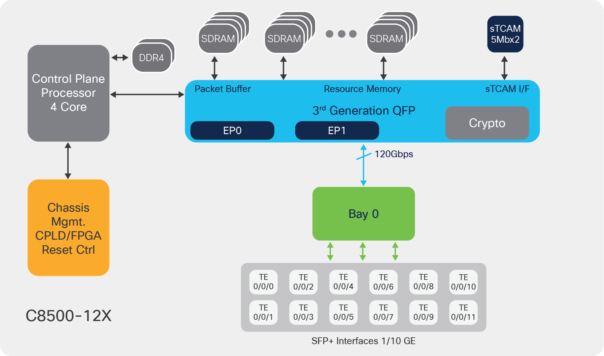
C8500-12X block diagram
● Most of the hardware entities in the C8500-12X edge platform are similar to those in the C8500-12X4QC edge platform.
● The key difference is that the C8500-12X platform has only EP1 for aggregating Ethernet port traffic within the QFP 3.0 system. This enables a maximum of 120 Gbps traffic input/output capacity via the bay 0 ports.
The Catalyst 8500 edge platforms honor a centralized forwarding architecture. For all forwarding features, decisions are applied on the packet flow at the data plane indirectly by the QFP 3.0. This is what makes all data plane services hardware accelerated. As the QFP 3.0 also hosts a Layer 2 subsystem as well as a dedicated crypto engine block, the critical functions of Layer 2 and crypto services also happen within the same ASIC.
The following steps elaborate on the details of the packet flow:
● Layer 1 checks at the interface PHY are processed at the built-in interface Rx path, and then packets get handed over to the QFP 3.0 Layer 2 subsystem.
● Layer 2 packet validations such as Cyclic Redundancy Check (CRC), Maximum Transmission Unit (MTU), and runt errors are checked on the integrated MAC on the QFP 3.0 Layer 2 subsystem.
● If the interface is enabled with MACsec, based upon the MACsec Key Agreement (MKA) the learned key packet will be decrypted. This is applicable if MACsec is enabled in configuration.
● Packets undergo default ingress classification or configured classification based upon the Physical Layer Interface Module (PLIM) QoS commands at the port level or VLAN level that put them into high and low priority queues in the ingress buffer. High-priority traffic is scheduled first prior to the low-priority traffic.
● Packets are stored in Global Packet Memory (GPM) and then the dispatcher within the QFP allocates incoming packets to the free PPE threads for feature application.
● Feature Invocation Arrays (FIAs) are applied one by one based on the ingress interface configuration for the forwarding process. If a packet needs to be decrypted, it gets handed over to the crypto engine prior to further processing.
● The crypto operation is done entirely within the crypto engine, which is equipped with dedicated compute and memory for cipher and digest algorithm application.
● After the ingress features are applied on the packet, Forwarding Information Base (FIB) lookup happens to figure out the egress path. Then the packets are enqueued for an egress operation based on the configured FIAs.
● After egress FIA processing, the packet gets copied from GPM to the packet buffer memory for further scheduling.
● The traffic manager schedules the packets based on Modular QoS configuration; the packets are enqueued into the output buffers.
● If the interface is enabled with MACsec, based upon the MKA the learned key packet will be encrypted.
● The Layer 2 subsystem within the QFP applies the egress processing at the MAC layer and sends packets toward the exit interface.
● Post-Layer 1 processing is done at the egress interface; the packets exit toward the next hop.
The Cisco IOS XE modular implementation at the control and data plane level, from Layer 2 to Layer 7 feature processing, makes sure that the packets are treated based on the configuration and that the services get applied one by one. At every stage, required flow control makes sure congestion situations are handled gracefully, treating high-priority traffic ahead of low-priority traffic.
The following are the key points for the various types of packet processing:
● When unicast Cisco Express Forwarding packets reach the data plane, first the ingress features are applied, followed by FIB lookup and then the egress features, as per the exit interface configuration. The Layer 2 features for ingress and egress get applied at the Layer 2 subsystem in the QFP 3.0.
● Multicast traffic can see real benefits from the rich and powerful design of the QFP 3.0. The packet replication for 1:N multicast happens with the help of recycling at the QFP level using 896 threads of raw forwarding power. Post replication, the replicated packets complete FIB lookup and are forwarded toward the egress interface.
● Crypto traffic does not need to be sent to an external ASIC for encryption or decryption functions from the data plane ASIC. The QFP 3.0’s built-in crypto engines take care of hardware-accelerated crypto functions with inline implementation, making it more effective.
● Traffic destined for the control plane will get punted by the data plane to the IOSd process running on the quad-core CPU. The IOSd process generated/response packets get injected into the data plane for forwarding to the egress direction post FIB lookup.
The Catalyst 8500 Series edge platforms are designed to allow ingress oversubscription.
In the case of the C8500-12X4QC, a maximum of 240 Gbps of traffic aggregation is possible. As shown in the figure below, bay 0 and bay 1 together can allow 120 Gbps of traffic aggregation, and bay 2 individually can allow 120 Gbps of traffic aggregation. This is achieved in various port-configuration options discussed later in this document.
All the built-in ports support synchronous Ethernet and WAN MACsec capabilities. WAN MACsec offers line-rate encryption capabilities.

C8500-12X4QC oversubscription capacity
The C8500-12X platform, on the other hand, allows a maximum 120 Gbps of traffic aggregation via the single bay 0 available on its front panel port.
The Catalyst 8500 Series offers Ethernet port capacity starting with 1 GE, 10 GE, 40 GE and 100 GE via the front panel interfaces.
The following table lists the 8500 Series port variations.
Table 1. Port configurations for the Catalyst 8500 Series
| Option # |
Port type |
Configuration |
| 1 |
100 GE |
2x 100 GE |
| 2 |
100/40 GE |
1x 100 GE + 3x 40 GE |
| 3 |
100/40 GE |
1x 100 GE + 12x 10 GE |
| 4 |
40/10 GE |
4x 40 GE + 8x 10 GE |
| 5 |
40/10 GE |
3x 40 GE + 12x 10 GE |
| 6 |
100/40/10 GE |
1x 100 GE + 1x 40 GE + 8x 10 GE |
| 7 |
10 GE |
12x 10 GE + 12x 10 GE (using breakout cable) |
| 8 |
1 GE |
12x 1 GE |
Note: The 1 GE or 10 GE port’s speed is detected based on the SFP or SFP+ used in the port.
The following figures depict the various port configuration options.
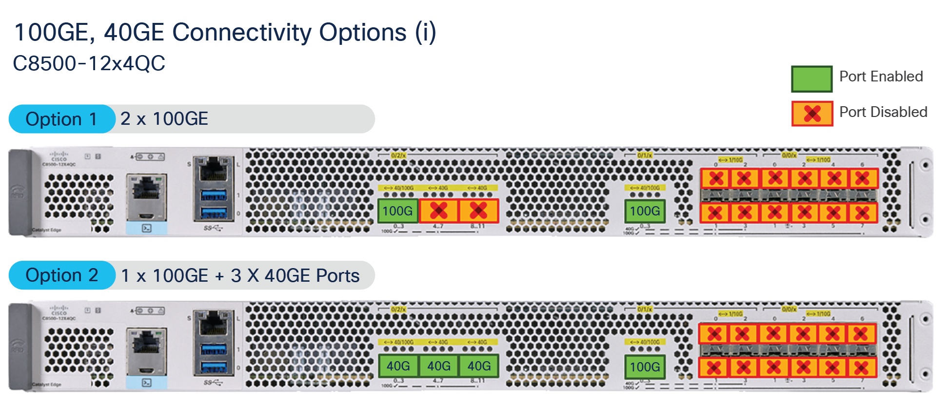
100 GE and 40 GE connectivity options for the C8500-12X4QC model
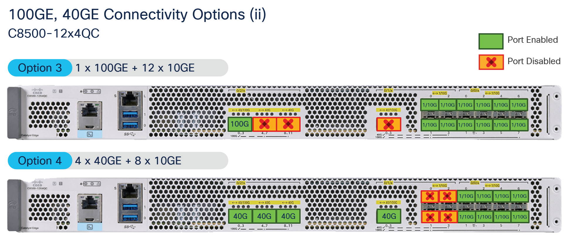
100 GE and 40 GE connectivity options for the C8500-12X4QC model (continued)
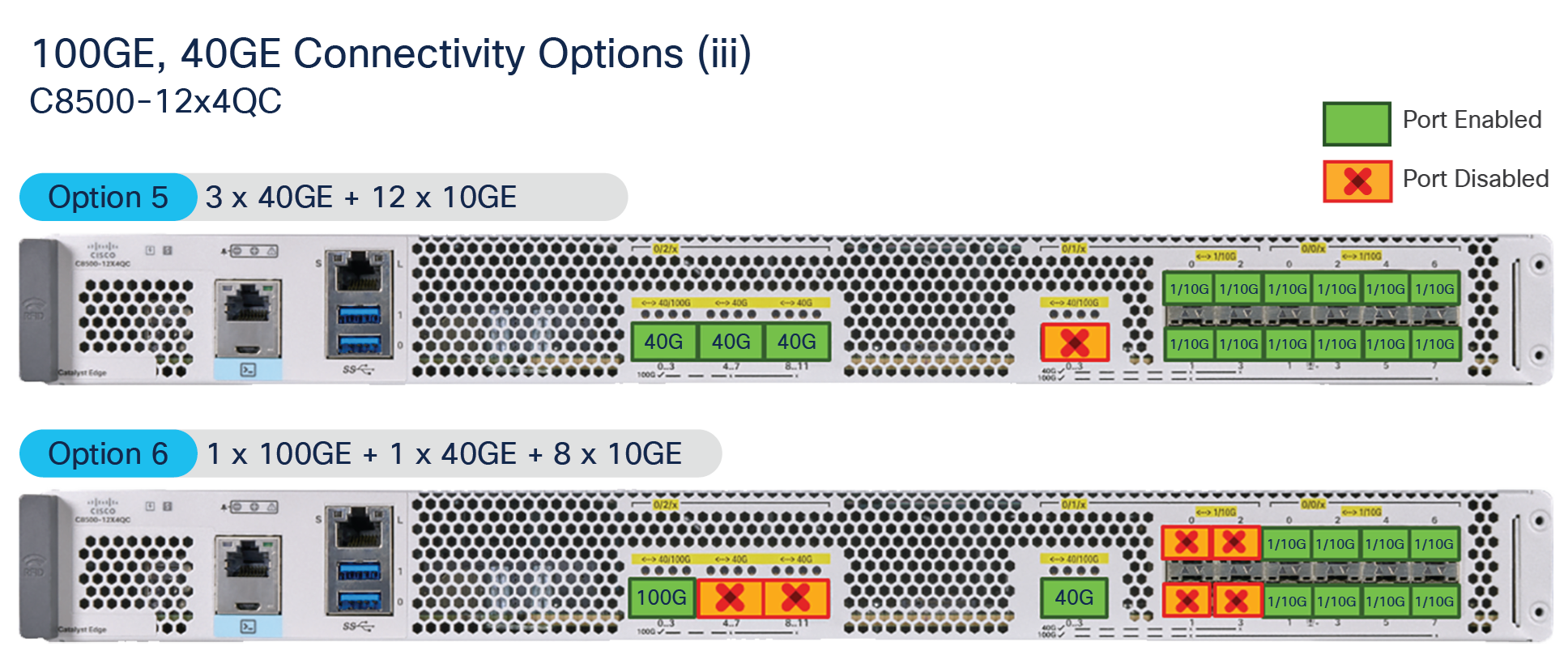
100 GE and 40 GE connectivity options for the C8500-12X4QC (continued)
For high-density 10/1 GE use cases, both the C8500-12X4QC and the C8500-12X can be used with 12 total 10/1 GE interfaces.
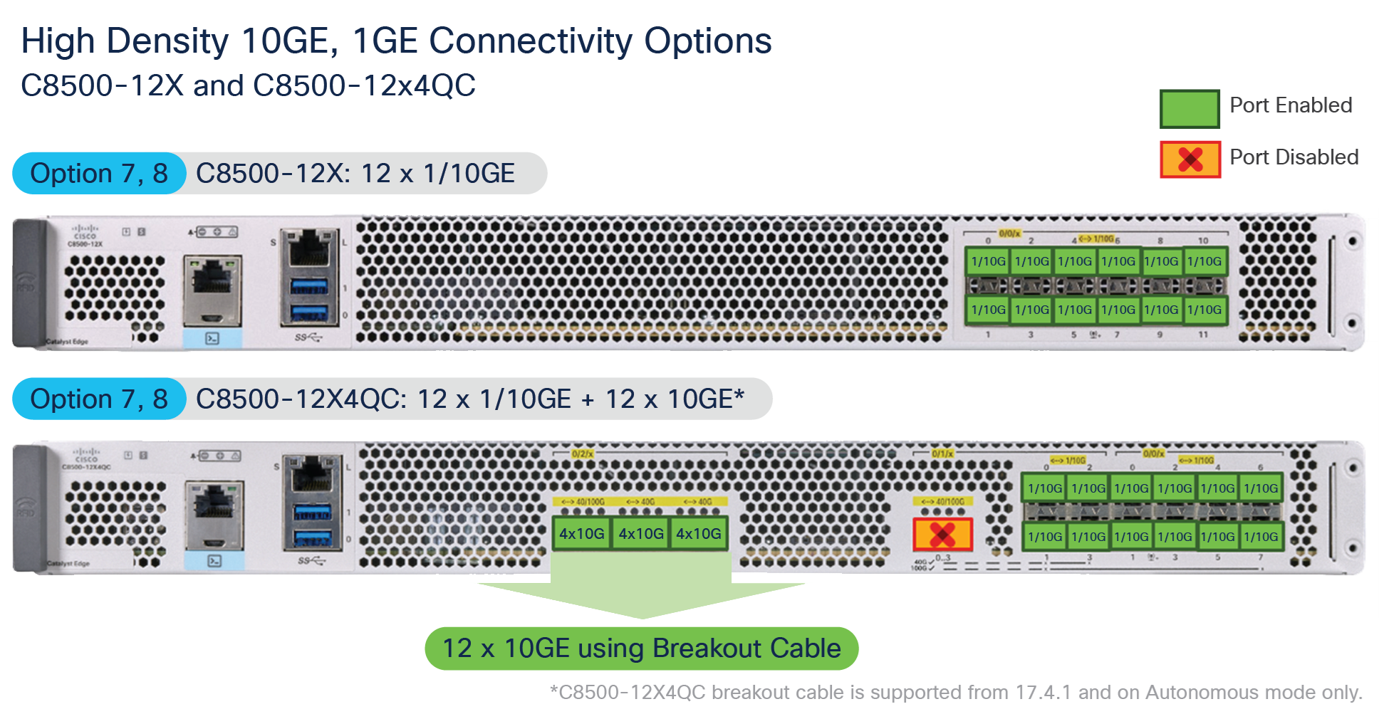
High-density 10 GE, 1 GE connectivity options
The top-end C8500-12X4QC model can support bay 2 ports configured in 40 GE for four breakouts of 10 GE each. With this configuration you can have a maximum of 24x 10 GE ports available in the 1RU form of the C8500-12X4QC platform. At present the breakout cable option is supported for the traditional routing “autonomous mode” of operation.
Both Catalyst 8500 Series platforms are equipped with 32 GB of bootflash memory for internal storage and a default of 16 GB of DRAM memory for control plane operation. The DRAM is upgradable to 32 GB or 64 GB based on the use case. For additional storage, a 480-GB M2 SATA SSD is available.
The C8500-12X4QC platform has a dedicated 80-Mb TCAM, whereas the C8500-12X platform has a 10-Mb TCAM. The TCAM is used for classification feature scale such as ACE, QoS, Network Address Translation (NAT), firewall, etc., where quick lookups and services application are desired. The route scale and other control plane scale are achieved using DRAM available on the platform.
The Catalyst 8500 Series has a redundant power supply system for AC or DC power sources. The AC power supply (PWR-CH1-750WACR) is 750W, whereas the DC power supply (PWR-CH1-950WDCR) is 950W. The two modules work in load-sharing mode to enable 1 + 1 power supply redundancy. Each power supply module has its own cooling with built-in fans. The DC power supply’s input connector is a two-wire screw-type connector with connection polarity from left to right (when facing the unit) of positive (+) and negative (–). Both power supply modules adhere to the Platinum power efficiency (≥ 90%) standard.
The fan module in the Catalyst 8500 platforms is replaceable. It has six fans in total, which are supplied power individually from the power source. This helps the platform achieve N + 1 redundancy such that, if one of the fans stops working, the remaining fans will continue the cooling function for the chassis. In addition, the fan tray module is field replaceable. The fans in the power supply module are used for cooling the power supply itself, while system-level cooling is provided by the fans within the chassis. The power supply does not depend on the system-level fans for cooling. Fan failure is determined by fan-rotation sensors. The airflow direction is front to back for the chassis as well as for the power supply fans.
Overall, the Catalyst 8500 Series edge platforms are purpose-built for today’s emerging WAN solutions.
Catalyst 8500 Series: Best-in-class 1RU enterprise aggregation platforms
The Catalyst 8500 Series has a powerful QFP 3.0-driven data plane, a highly scalable control plane, built-in interface flexibility with options for 100 GE, 40 GE, 10 GE, and 1 GE and more importantly, hardware-accelerated services.
The Catalyst 8500 Series offers best-in-class hardware with rich software features for high-performance traditional routing and emerging SD-WAN and colocation use cases.
Learn more about the capabilities of the Catalyst 8500 Series edge platforms:
● Catalyst 8500 Frequently Asked Questions
● Cisco Catalyst TV YouTube Channel