Cisco Catalyst CW9166D1 Access Point Deployment Guide
Available Languages
Bias-Free Language
The documentation set for this product strives to use bias-free language. For the purposes of this documentation set, bias-free is defined as language that does not imply discrimination based on age, disability, gender, racial identity, ethnic identity, sexual orientation, socioeconomic status, and intersectionality. Exceptions may be present in the documentation due to language that is hardcoded in the user interfaces of the product software, language used based on RFP documentation, or language that is used by a referenced third-party product. Learn more about how Cisco is using Inclusive Language.

The Cisco Catalyst 9162I, 9164I, 9166I and 9166D1 access points (APs) are the first in Cisco’s history to have a common hardware that has the capability to join either an on-premises Cisco Catalyst and Catalyst-based wireless LAN controller or a cloud-based Cisco Meraki wireless network.
Cisco understands that selecting your next platform is not an easy choice. With the Cisco Catalyst Wi-Fi 6E access points, you don’t need to make the decision now. Keep the operational mode you use today, whether on premises or cloud management. If your needs change—either way—it’s an easy switch. No new hardware required. That’s investment protection for your network that you can count on.

Cisco Catalyst 9162I, 9164I, 9166I and 9166D1 all use common hardware for on-prem and cloud operation.
Cisco Catalyst CW9166D1 overview
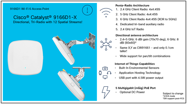
The Cisco Catalyst CW9166D1 is very similar to the Cisco CW9166I – internal hardware features and functionality are essentially the same as the Catalyst CW9166I with a few features added that we will discuss later in this paper. The take-way is that the CW9166I has an omni-directional antenna and the CW9166D1 has an integrated directional antenna array.
This internal directional antenna differs slightly from previous directional AP products that used external (removeable) antennas. This is due mostly to regulatory constraints placed upon products operating using 6 GHz (Wi-Fi 6E) especially when the product covers the entire 6 GHz spectrum, and when the desire is to focus the AP’s energy into a given direction.
Low Power Access Points such as the Catalyst CW9166D1 can operate in the entire spectrum of 6 GHz, and as such must comply with regulatory agency rules in different countries (theaters) that often specify that products covering a large spectrum in 6 GHz must be for indoor use only with an integrated antenna and cannot have any external attached antenna or have weather-resistant enclosures.
Products with a limited spectrum coverage may support external antennas and be used outdoors but due to the limited spectrum coverage mostly UNII-5 and UNII-7 – it makes sense to integrate the directional antenna into the CW9166D1 allowing it the most flexibility and spectrum coverage for indoor use.
CW9166D1 is a Cisco Wi-Fi 6E access point platform, with a penta-radio architecture providing the full capability of 802.11ax, such as orthogonal frequency-division multiple access (OFDMA), multiuser multiple-input multiple-output (MU-MIMO), Target Wake Time (TWT), BSS Coloring, overlapping BSS packet detection (OBSS-PD), and Wi-Fi Protected Access 3 (WPA3), all while being able to leverage advanced RF visibility with Cisco CleanAir® Pro together with an artificial intelligence and machine learning (AI/ML)-driven scanning radio.
The Catalyst CW9166D1 when operated in with the Cisco Catalyst Wireless LAN controller supports the entire Cisco Catalyst wireless stack functionality with Cisco Catalyst Center (Automation and Assurance), Cisco Spaces (formerly Cisco Catalyst Spaces) (location and IoT), Cisco Identity Services Engine (ISE) (security), and more.
The Catalyst CW9166D1 is an indoor Wi-Fi 6E AP that operates in Low Power mode using capabilities listed in the table below.
Table 1. Cisco Catalyst CW9166D1 capabilities
| Feature |
CW9166D1 |
Comments |
| 2.4 GHz (slot 0) |
4x4:4SS |
|
| 5 GHz (slot 1) |
4x4:4SS |
|
| 5 GHz (slot 2) |
4x4:4SS |
The CW9166D1 has an XOR radio that can operate in 5+5 or 5+6 GHz |
| 6 GHz (slot 2) |
4x4:4SS |
|
| AI/ML-driven scanning radio |
Yes |
|
| 2.4-GHz IoT radio |
Yes |
For Bluetooth Low Energy (BLE) purposes |
| Ethernet |
5 Gbps (Multigigabit) |
|
| USB |
Up to 4.5W |
|
| Power options |
802.3af/at/bt DC input power: 54V |
|
| Environmental sensors |
Yes |
Air quality, humidity, and temperature |
Catalyst CW9166D1 is similar in hardware to the 9166I except it has an integrated directional antenna and is slightly wider and is available with an optional articulating mount.

Catalyst CW9166D1 AIR-AP-BRACKET-2 is used often in conjunction with an optional articulating mount allowing the AP to be placed at ceiling height or higher and then angled downward to cover a particular area.

CW9166D1 is an ideal product for auditoriums and other places where focused connectivity is desired.
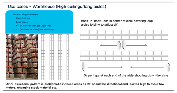
CW9166D1 is an ideal product for auditoriums and other places where focused connectivity is desired in a warehouse environment.

CW9166D1 can be wall mounted instead of traditional ceiling mounted Access Points when the desire is to cover long hallways.

CW9166D1 can be used in areas with really high ceilings as the directional antenna can focus downward into a given area.
It is recommended when mounting Access Points to locate them as close to the users as possible, in the case of extremely high ceilings, Access Points with directional antenna arrays such as the CW9166D1 can improve the range of the client allowing the antenna to be mounted typically higher than the recommended distance of 10-15 Feet. Always be sure to test the connectivity during the installation process when the ceiling height exceeds 18 Ft.
Also, when co-locating units especially in close proximity, it is a good practice to test both units operating concurrently at heavy load (and then test each unit individually at heavy load) to verify the units are not interfering with each other. Whenever a unit is in close proximity of another unit (always try to space the operating channels <frequencies> as far apart as practical) verify any degradation that may occur is acceptable if not try reducing RF power or relocating the units. Anytime a unit is in very close proximity to another unit the potential of RF degradation (desense) can occur.
Cisco Catalyst CW9166D1 co-location

CW9166D1 can be co-located but care must be taken to separate the frequencies and fully test to determine if there is any degradation.
Table 2. Supported Cisco IOS XE Software for the CW9166D1.
| Catalyst 9800 controller software release |
| Cisco IOS XE 17.12.1 and later for Catalyst CW9166D1 |
Supported wireless controller platforms
The Catalyst CW9162I, CW9164I, CW9166I and CW9166D1 are supported in the following wireless controller platforms:
● Catalyst 9800-L
● Catalyst 9800-40
● Catalyst 9800-80
● Catalyst 9800-CL (virtual controller for both private and public cloud)
Access point capability matrix
Table 3. Cisco Catalyst CW9166D1 capability matrix
| Feature |
|
CW9166D1 |
|
|
| Scale |
|
1200 clients total (400 clients per radio) |
|
|
| Client-serving radios |
|
4x4 2.4 GHz 11ax, 4x4 5 GHz 11ax, 4x4 6 GHz 11ax (or) 4x4 2.4 GHz 11ax, (dual 5 GHz) 4x4 5 GHz 11ax, 4x4 5 GHz 11ax |
|
|
| Features |
|
Download and upload OFDMA and MU-MIMO, BSS Coloring, TWT |
|
|
| LAN port |
|
PoE-IN Multigigabit 5 Gbps |
|
|
| Ports |
|
mGig0, console |
|
|
| Antenna |
|
Integrated - Directional |
|
|
| Dimensions (W x L x H) |
|
9.5 x 9.5 x 2.3 in. |
|
|
| Weight |
|
3.5 lb. (1.60 kg) |
|
|
| SSIDs |
|
2.4 GHz: 16, 5 GHz: 16, 6 GHz: 8. |
|
|
Please refer to the product data sheet for the complete product specifications.
Catalyst CW9166 Series data sheet: https://www.cisco.com/c/en/us/products/collateral/wireless/catalyst-9166-series-access-points/catalyst-9166-series-access-points-ds.html
The Catalyst CW9166D1 are interoperable with the network management and security solution in the table below.
Table 4. Software interoperability matrix
| Access point |
Catalyst 9800 |
Cisco Catalyst Center |
Cisco Prime Infrastructure |
Cisco CMX |
Cisco Spaces |
Cisco ISE |
| Catalyst CW9166D1 |
17.12.1 |
2.3.7.x |
N/A |
11.0.0-154 |
2.3.2+ |
2.6 and above |
The following tables provide the different power options for the Catalyst CW9166D1.
Table 5. PoE specifications for the Catalyst CW9166D1
| Number of spatial streams |
2.4-GHz radio |
5-GHz radio |
5-GHz / |
mGig link speed |
USB |
Max power draw |
|
| 802.3af |
– |
– |
– |
– |
1 Gbps |
Disabled |
14.0W |
| 802.3at |
12 |
4x4 |
4x4 |
4x4 |
5 Gbps |
Disabled |
25.5W |
| 802.3bt |
12 |
4x4 |
4x4 |
4x4 |
5 Gbps |
Y/4.5W |
30.5W |
| DC power |
12 |
4x4 |
4x4 |
4x4 |
5 Gbps |
Y/4.5W |
|
Notes:
1. External power injector model: AIR-PWRINJ7 or Meraki MA-INJ-6.
2. 802.3af is only for day-0 Control and Provisioning of Wireless Access Points (CAPWAP) connectivity between the AP and the Catalyst 9800 controller.
The Catalyst CW9166D1 has a brand-new design compared to the previous Catalyst 9100 Wi-Fi 6 APs. It is designed with two ridges on the top, allowing you to identify them among the other APs instantly. Not only is the design aesthetically pleasing and very functional. A larger recessed cable access area is provided for better access to cabling and faster, easier deployment.
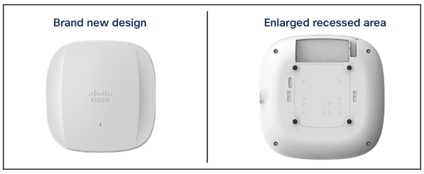
Front and back view of Catalyst CW9166D1 – Uses standard Cisco metal bracket and has a larger recessed area for cabling.
Note: AIR-AP-Bracket-2 is the default and preferred bracket for the CW9166D1
This enlarged recessed area allows cables to be inserted into the ports without bending, for an improved cabling experience. This is depicted in the figure below, when compared with a Catalyst 9130 Series AP.

Comparison of cabling experience of Catalyst CW9166D1 vs. Catalyst 9130AXI on the right
The Catalyst CW9166D1 has an incredible ratio of dimensions/weight to performance. They are similar in size and weight to the midrange and high-end Catalyst Wi-Fi 6 APs and smaller and lighter than many of the Cisco Aironet APs. However, they boast a much more robust penta-radio architecture and support the entirety of Wi-Fi 6E.
Refer to the figures below for the dimensions and weight.

Dimensions and weight of the Catalyst CW9164I, CW9166I and CW9166D1
The following figure depicts the ports and reset button on the Catalyst CW9166D1.
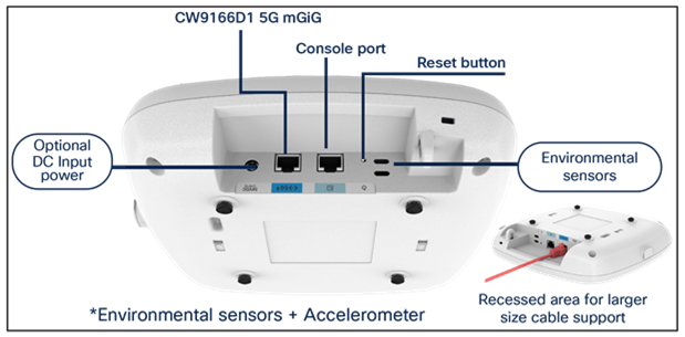
Physical ports and buttons of the Catalyst CW9166D1
Ethernet port
The Catalyst CW9166D1 comes with a 5-Gbps uplink port.
Console port
The console port (RJ-45) is used to access the AP’s command-line interface (CLI).
DC input power
The Catalyst CW9166D1 has an optional DC input power of 54V to operate the AP at full capability.
Reset button
The Reset button is used to reset the AP to the factory settings.
Follow these steps to reset the AP.
1. Connect the console cable.
2. Unplug the PoE network cable from the switch.
3. Press and hold the Reset button.
4. Plug the power back into the AP.
5. Wait until the output on the console says “Button pressed. Configuration Reset is Activated.” Hold the button for 20 seconds for a full configuration reset and 30 seconds for a factory reset. Once the button is released, the AP will reboot to the state listed above.
Environmental sensors
The Catalyst CW9166D1 has three built-in environmental sensors: air quality, humidity, and temperature. As shown in Figure 5, the openings on the right are where these sensors are located on the AP.
More details on these sensors are provided in the “Internet of Things Integration” section of the 9166I deployment guide at this URL: https://www.cisco.com/c/en/us/products/collateral/wireless/catalyst-9164-series-access-points/catalyst-9166i-9164i-dg.html.
The use of proper cable types will directly affect the performance of the Catalyst CW9166D1. Since this AP has a 5-Gbps port, the recommendation is to use either CAT6 or CAT6a cable, which support speeds of up to 10 Gbps. CAT5e cables can still be used; however, there may be an effect on the AP’s performance.
Refer to the table below to compare cable types that can be used with the Catalyst CW9166D1.
Table 6. Cable types supported.
| Cable type |
Speeds |
Maximum length |
| CAT5e |
5 Gbps |
328 feet (100 meters) |
| CAT6 |
1, 2.5, or 5 Gbps |
330 feet (100 meters) |
| 10 Gbps |
164 feet (50 meters) |
|
| CAT6a |
10 Gbps |
330 feet (100 meters) |
Regarding mounting, the Catalyst CW9166D1 uses AIR-AP-Bracket-2 as the default bracket. While AIR-AP-BRACKET-1 would fit the CW9166D1 that bracket is designed for ceiling mounting and therefore is better suited for the Catalyst CW9166I as it is designed for ceiling installations whereas the CW9166D1 with its directional antenna array is primarily designed for wall mounting.
For more details on mounting the APs, refer to the following:
● Access Point Mounting Instructions

Mounting options for Catalyst CW9166D1
The following figures provide details about the AIR-AP-Bracket-2 for reference.
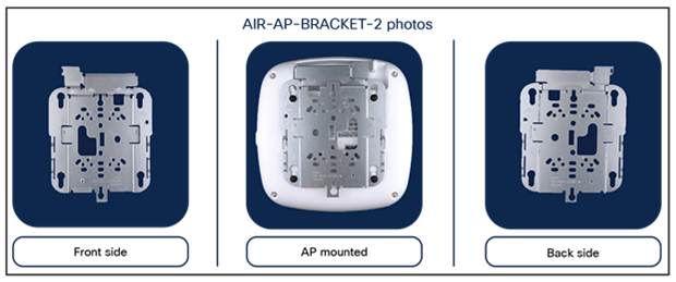
AIR-AP-BRACKET-2
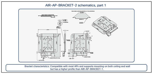
AIR-AP-BRACKET-2 schematics

AIR-AP-BRACKET-2 schematics continued

Dimensions for CW-MNT-ART2-00 Articulating mount (connects to AIR-AP-BRACKET-2)
Wi-Fi 6E takes the 802.11ax protocol to the next level by introducing a brand-new spectrum, 6 GHz. This new spectrum is much wider than the legacy bands (2.4 GHz and 5 GHz) and allows wireless devices to take advantage of the performance enhancements introduced with Wi-Fi 6. The new spectrum is reserved for greenfield Wi-Fi 6 client operation only. This means that no previous generations of Wi-Fi will be permitted to operate there. This eliminates the performance-robbing requirements of backward compatibility often experienced in previous spectrums. In addition, the amount of spectrum provided encourages and enables the use of wider 80- and 160-MHz channels, which dramatically increases the speed while simultaneously providing enough room to operate without the co-channel interference issues experienced in the 2.4- and 5-GHz spectrums.
Wi-Fi 6E migration and deployment tips
Wi-Fi 6E (6 GHz) is a new spectrum standard, and with it comes several new requirements that were not present in the past. This section goes over key points about Wi-Fi 6E that play a part in the deployment of the CW9166D1 APs.
The figure below depicts a high-level representation of Cisco’s recommendations, tips, and tricks for deploying the Catalyst CW9166D1 APs, while the sections that follow expand upon the details of each.
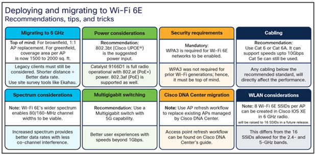
Wi-Fi deployment and migration recommendations, Note AP coverage 1500-2000 square ft. however, the CW9166D1 this coverage is not Omni-directional so while the amount of sq foot is essentially the same, the amount of footage is focused in a directional 70-degree pattern at 2.4 and 5 GHz and 60-degree at 6 GHz. Additionally, SSIDs are limited to 8 SSIDs on 6 GHz band.
Migration to 6 GHz
When deploying a new Wi-Fi 6E AP, there are two categories of considerations: whether you have a greenfield (no existing APs) or a brownfield (have existing APs) deployment.
Brownfield deployment: While we always recommend that you conduct site surveying and wireless coverage planning with tools such as Ekahau or iBwave, the general rule of thumb for a brownfield deployment is to have a one-to-one AP replacement. The reason is that you will likely still have to serve legacy band clients such as 2.4 or 5 GHz. If the legacy APs were strategically placed at the current location using an external 6 dBi directional antenna for the best legacy band coverage, the Catalyst 9166D1 will likely provide the best coverage there.
Greenfield deployment: If there are no existing APs, the suggestion is to use Ekahau or iBwave to conduct proper wireless planning before deploying any APs physically to ensure the best wireless coverage.
Power considerations
The Catalyst CW9166D1 support three power types: 802.3bt (Cisco UPOE®, equivalent to 60W), 802.3at (PoE+, equivalent to 30W), and 802.3af (PoE, equivalent to 15W) or through DC input power. The AP can be powered by any of these power types; however, to get all the capabilities of the AP, an input power of 802.3bt must be used. Refer to the “Power Options” section above for a detailed overview of what input power type supports what radio, port, and USB settings.
When it comes to selecting a proper switching infrastructure to connect and power your wireless infrastructure, there are several factors to consider. To ensure that you have the most optimal switching infrastructure deployed, refer to the following Cisco UPOE+ white paper: https://www.cisco.com/c/en/us/solutions/collateral/enterprise-networks/nb-06-upoe-plus-it-ot-wp-cte-en.html.
Multigigabit Switching
The Catalyst CW9166D1 has one 5-Gbps Multigigabit port, so to take advantage of its performance, your switches need to support Multigigabit speeds.
To learn more about Cisco Multigigabit switching technology, refer to the following webpage: https://www.cisco.com/c/en/us/solutions/enterprise-networks/catalyst-multigigabit-switching/index.html#~benefits.
6-GHz spectrum considerations
With the introduction of Wi-Fi 6E, the spectrum has been significantly expanded compared with 5 GHz and especially 2.4 GHz. Spanning from 5925 MHz to 7125 MHz, we now have 59x 20-MHz channels, 29x 40-MHz channels, 14x 80-MHz channels, and 7x 160-MHz channels.
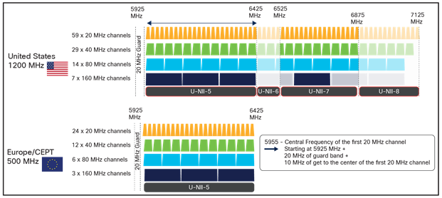
The 6-GHz spectrum
Certain countries have yet to allow parts of or the entire 6-GHz spectrum. At the time this document was written, Europe/CEPT has approved only 5925 MHz to 6425 MHz, compared to the U.S., which has approved the whole spectrum.
The increase in spectrum width provides several advantages, with one of the most prominent being a lowered risk of co-channel interference. Since there are more channels to select from, it’s much less likely that APs in a similar physical location will be broadcasting RF on the same channels. In the past, this concern for co-channel interference is what prevented users from taking advantage of 80-MHz or 160-MHz bonded channel widths. Although throughput tests showed that they could provide great performance numbers, the problem was that deploying them in such a fashion was simply not practical in most production enterprise settings, because fewer channels meant a greater chance of interference and reduced overall capacity. With the introduction of Wi-Fi 6E, 80 and 160 MHz can now be used, allowing us to take advantage of the increased speeds in a production scenario.
To configure your access point’s 6-GHz radio as 80 or 160 MHz, navigate to the following in your Catalyst 9800 controller: Configuration > Wireless > Access Points > [Select a 6 GHz radio] > Configure > Channel Width > [select 80 MHz or 160 MHz] > [Click Update and Apply to Device].

Configuring a 6-GHz radio channel width – Note screen shots may be different depending upon version of software etc.
The instruction above demonstrates how to change the channel width manually as a reference. However, we recommend using the Catalyst 9800’s radio resource management (RRM) feature with dynamic channel and bandwidth selection to automatically determine the channel and bandwidth the radios should be serving on for best performance. Refer to the “6-GHz Radio Resource Management” section below for more details.
Another benefit of the 6-GHz spectrum is that it is still clean and without much interference compared with legacy bands such as 2.4 GHz, which shared the spectrum with the likes of BLE, Zigbee, microwave, and various other RF devices. With 6 GHz, we can expect that most of the spectrum use will be by other Wi-Fi 6E wireless clients of similar speeds, resulting in not only a more efficient spectrum but also a more secure one, thanks to the WPA3 mandate described in the “Security Requirements” section below.
Security requirements
Wi-Fi 6E requires that all WLANs be configured with WPA3 and Opportunistic Wireless Encryption (OWE), together with Protected Management Frames (PMF) enabled in both the AP and the client. Because previous bands didn’t require WPA3, this requirement allows Wi-Fi 6E to be the most secure spectrum. From a deployment perspective, this will likely affect how you create WLANs, since many legacy clients might not support WPA3 security. This is covered in the “WLAN Design Considerations” section.
The requirement to configure a Wi-Fi 6E WLAN with WPA3 security is not specific to Cisco but general to Wi-Fi 6E and applies to all vendors.
To learn more about WPA3, refer to the WPA3 Deployment Guide: https://www.cisco.com/c/en/us/products/collateral/wireless/catalyst-9100ax-access-points/wpa3-dep-guide-og.html.
Wireless coverage planning
6 GHz is a new spectrum and therefore requires special planning and site surveying to determine the best areas for AP placement, especially in greenfield deployments. While 6 GHz provides faster speeds, its wavelengths are shorter, meaning that its range is shorter as well compared to 5 and 2.4 GHz. This factor may result in the Catalyst CW9166D1 being placed in slightly different location than previous APs that broadcast only 2.4 and 5 GHz to ensure optimal RF coverage in a greenfield deployment.
Cisco recommends always conducting a site survey and using Ekahau or iBwave for wireless planning. These tools will allow you to upload floor plans of your building and simulate the RF of a Catalyst 9166D1 to determine where the APs should be placed for the best coverage. Once you’ve determined the optimal locations for your Catalyst CW9166D1 you can deploy them physically.
Cisco Catalyst Center AP refresh workflow
When migrating to new APs in a brownfield deployment, the new APs often take the place of incumbent APs with a one-to-one replacement. Assuming that your wireless infrastructure is being managed by Cisco Catalyst Center, you would also need to replace both the APs managed by the inventory and those assigned to a floor map. To do this efficiently, Cisco Catalyst Center has an AP refresh workflow that allows you to easily replace old APs with new ones. This eliminates the tedious manual process of deleting old APs and streamlines the entire workflow.
Refer to the Build and Deploy Workflows chapter of the Cisco Catalyst Center User Guide for reference on the AP refresh workflow: https://www.cisco.com/c/en/us/td/docs/cloud-systems-management/network-automation-and-management/dna-center/2-2-3/user_guide/b_cisco_dna_center_ug_2_2_3/m_dnac_workflows.html.
WLAN design considerations
As stated in the “Security Requirements” section, for an SSID to be broadcast on 6 GHz you need:
● WPA3 or OWE as Layer 2 security.
● Protected Management Frames (PMF).
● No other Layer 2 security method is allowed – a mixed mode is not possible.
On one hand this is good, because it makes 6 GHz extremely secure, but it also means that you need to reconsider your SSID/WLAN design, as multiple legacy clients you have in your network might not support these requirements, and most likely your current WLAN configuration would prevent them from being supported on 6 GHz.
So how would you design your SSID and define your security settings to adopt 6 GHz but at the same time guarantee backward compatibility for existing clients?
There are three options available:
1. “ALL-IN” Option: Reconfigure the existing WLAN to WPA3, one SSID for all Radio Policies (2.4/5 and 6 GHz).
2. “One SSID” Option: Configure One WLAN profile with WPA2+WPA3 Transition Mode as the Security.
3. “Multiple SSIDs” Option: Re-design your SSIDs adding specific SSID/WLAN with specific security settings.
The recommended option for enterprise is to add a separate WPA3 SSID (Option 3), with a different SSID name, and broadcast it in all bands. The WPA3-capable clients in the 2.4-GHz, 5-GHz, and 6-GHz bands would be able to connect and enjoy the most secure wireless network possible. Since you are not touching your existing SSIDs, legacy clients not supporting WPA3 will continue to connect to legacy SSIDs. The drawback of this option is that you need to broadcast an additional SSID, and you need to manage an additional wireless profile on the new WPA3-capable clients.
Example:
A new SSID with WPA3 with dot1x only Security for employees and an SSID with WPA3 with SAE for guest.
Existing SSIDs (2.4/5 GHz):
Corporate SSID: employee Security: WPA2 with dot1x
Guest SSID: guest Security: WPA2 with PSK
New SSIDs (2.4/5/6 GHz):
Corporate SSID: employee_wpa3 Security: WPA3 with dot1x
Guest SSID: guest_wpa3 Security: WPA3 with SAE
However, in the education sector (Example: eduroam), there will be a need to have the same SSID name across all the bands with support for older security mechanism like WPA/WPA2 and at the same time support for only WPA3 in 6 GHz band.
If there is a requirement to keep the SSID name the same, another option (Option 2) would be to create a WLAN profile and configure the security settings with WPA2+ WPA3 and PMF as optional. This will make the SSID in 2.4 and 5 GHz to be transmitted with WPA2+WPA3 Transition Mode and PMF as Optional. The SSID will be transmitted with WPA3 Only and PMF Required in 6 GHz radio.
WPA3 Transition Mode
WLAN Security Configuration for 2.4/5 GHz - > Enable WPA3 Transition Mode (mixed mode).
● L2 Security would be WPA2 + WPA3.
● AKM should be set to 802.1x-SHA256 and 802.1x (SHA1).
● PMF set to optional.
WPA3 Transition Mode
Client-side settings
For clients that do not support 6 GHz, configure a WPA2 profile.
For clients that support 6 GHz, configure a WPA3 Enterprise. They will use this setting to connect to both 2.4/5 GHz and 6 GHz.
Pros:
● This provides an adoption path to more secure Wi-Fi via WPA3 Transition mode.
● No new SSID profile to be managed on the client side.
Cons:
● Older clients may have problem connecting to an SSID with WPA3 Transition mode.
Note:
The following blog walks through the different scenarios and options available that administrators can chose to deploy depending on their network conditions and requirements. https://blogs.cisco.com/networking/wlan-ssid-security-migration-into-6ghz-networks.
More details on WLAN creation can be found in the “Creating a Wi-Fi 6E WLAN” section below.
In Release 17.12.1, you are limited to eight Wi-Fi 6E SSIDs. However, this limit will be increased to the standard 16 SSIDs in a future release This limitation affects only 6 GHz; for legacy bands you can configure up to 16 SSIDs.
The workflow for creating a 6-GHz WLAN is like that for all legacy bands with only a couple of differences, one being the security requirement of WPA3.
To create a 6-GHz WLAN, navigate to Configuration > Tags and Profiles > WLANs > [Click +Add]. Input a Profile Name (WLAN profile identifier) and SSID (Wi-Fi name being broadcasted), and then change the Status to Enabled.

WLAN creation
Notice that although 6 GHz is enabled, it’s highlighted in red. This is because by default, the security of WLANs is set to WPA + WPA2, which doesn’t meet the requirement of 6 GHz. Notice that the text within the 6 GHz Status box highlights the requirements.
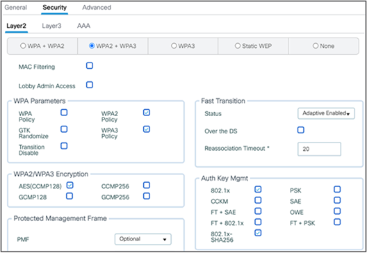
To change the security to WPA3, click the Security tab and then, from the radio button menu located at Layer2 > select WPA3.

Configuring security parameters
Select at least one Authentication Key Management (AKM) option: Secure Agile Exchange (SAE), OWE, Fast Transition (FT) + 802.1X, or 802.1X-SHA256.
Navigate back to the General tab, and you’ll notice that the 6 GHz Status is now enabled and green, meaning that all configurations are satisfactory. Click Apply to Device to complete the WLAN creation workflow.

6-GHz radio status in WLAN
Option: If you want to verify that 802.11ax features such as downlink and uplink OFDMA, downlink and uplink MU-MIMO, and BSS Target Wake Time are enabled, click Advanced, and scroll to the bottom.

Enabling 11ax features (IOS-XE 17.12.1)
AP discovery is how wireless clients discover APs with WLANs that they would like to join. The legacy method includes two options, passive scanning, and active scanning.
Passive scanning: The AP will periodically broadcast beacon frames that the wireless client can detect, providing metadata for each WLAN the AP is broadcasting, such as the SSID name, data rates, etc.
Active scanning: The wireless client will send probe requests to nearby APs when it wants to join a WLAN. If an AP detects this probe request, it will send back a probe response with WLAN information such as the SSID name, data rates, etc.
In both cases, using the information received from the AP in either the beacon frame or probe response, the wireless client can request to join the AP’s WLAN.

Legacy AP discovery mechanisms
These methods worked well with the previous 2.4- and 5-GHz bandwidth networks, since 2.4 GHz had only 3x 20-MHz channels and 5 GHz had 25x 20-MHz channels, as depicted in the figure below.
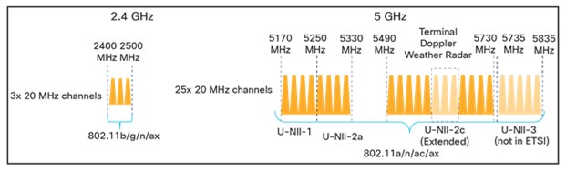
Depiction of 2.4- and 5-GHz spectrum
However, with the introduction of 6 GHz, we now have 59x 20-MHz channels (depicted in the figure below), more than two times what we had in 5 GHz. Because wireless clients can send probe requests only on 20-MHz channels, this increases the passive scan time significantly to 6 seconds, which is far too much delay in the world of wireless.

Depiction of 6-GHz spectrum
Since legacy AP discovery mechanisms are not efficient when addressing the expanded spectrum of 6 GHz, new AP discovery mechanisms have been created. Of these new discovery mechanisms, there are two categories, out-of-band, and in-band discovery, as shown in the figure below.
Out-of-band discovery mechanism: Used when 2.4-, 5-, and 6-GHz bands all exist in the RF environment.
In-band discovery mechanisms: Used when only the 6-GHz band exists in the RF environment.

6-GHz WLAN discovery mechanisms
Out-of-band AP discovery mechanism
For the out-of-band discovery mechanism, we have the Reduced Neighbor Report (RNR), as depicted in the figure below, which includes WLAN information for all 6-GHz-capable WLANs within the beacon and probe responses of the AP’s 2.4- and 5-GHz radios. Concatenating all 6-GHz WLAN data into these existing frames eliminates the need for additional packets to be sent, which conserves airtime and allows the network to steer the clients toward 6 GHz if they are capable.
RNR is enabled by default as part of 6 GHz.
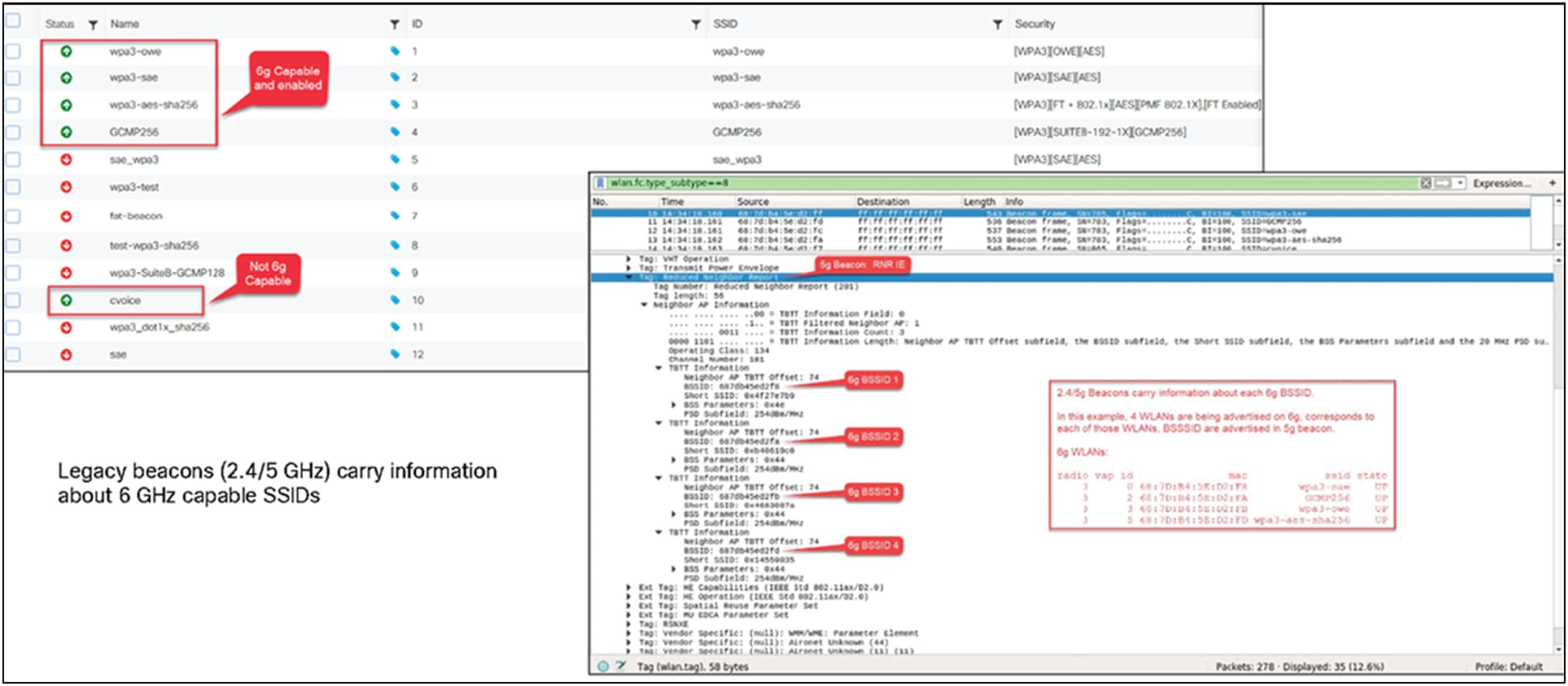
Visual representation of RNR

RNR IE shown in Wireshark
In-band AP discovery mechanisms
Fast Initial Link Setup
For the first in-band discovery mechanism, we have the Fast Initial Link Setup (FILS) frame, which is part of the 802.11ai standard. A problem that exists in wireless today is APs being overwhelmed by probe requests, and this is especially true in high-density environments. FILS directly addresses this and helps to make AP discovery in a 6-GHz band more efficient by reducing probe request overhead and prolonging a wireless client’s dwell time between beacon frames.
The following step-by-step explanation is based on the figure below.
1. APs broadcast beacon frames that contain detailed WLAN metadata every 100 ms.
2. If a wireless client starts WLAN discovery right after a beacon is sent, it will continuously send probe requests until the next beacon is detected, taking up airtime.
3. FILS frames, which are smaller than beacon frames, are sent every 20 ms between beacon frames and contain high-level WLAN information such as the short SSID name, channel, and Target Beacon Transmission Time (TBTT), but are sufficient to tell a wireless client whether the WLAN is something it wants to join.
4. If a client starts discovery right after a beacon frame is sent, within 20 ms it will detect a FILS frame. If it decides that this is a WLAN it would like to join, it will go into sleep mode (stop sending probe requests) until the next beacon frame is detected.
5. When the next beacon frame is detected, the wireless client will use the WLAN’s detailed metadata from that frame to join the WLAN.
Ultimately, FILS frames help to reduce the number of probe requests being sent from clients and make the airtime more efficient.

FILS discovery request frames shown in Wireshark
Unsolicited Broadcast Probe Response
The second in-band method is the Unsolicited Broadcast Probe Response (UBPR). When this feature is enabled and a client sends a probe request, the AP will send a probe response; however, rather than being sent to the client’s MAC address, the probe response is broadcasted, as the name suggests. Broadcasting the probe response enables other wireless clients to use this same probe response to join the WLAN, reducing probe request overhead. The UBPR frames are transmitted every 20 seconds, carry multiple BSSIDs, and contain all information needed for the association, as any normal beacon frame does.

UBPR frames in Wireshark
Enabling FILS or UBPR
FILS and UBPR are equivalent greenfield, in-band, 6-GHz discovery mechanisms.
To enable FILS discovery or UBPR, on your Catalyst 9800 controller, navigate to Configuration > Tags and Profiles > RF/Radio > [Select RF profile] > 802.11ax.
Next to 6 GHz Discovery Frames, you have the option to enable either None, Broadcast Probe Response, or FILS Discovery. The default is None. If you select Broadcast Probe Response, you can also configure the response interval if desired.

Configuring 6-GHz discovery on the Catalyst 9800 controller
Only one of these 6-GHz discovery frames methods can be enabled at a time.
6-GHz radio resource management
Radio resource management (RRM) is a collection of algorithms that allow the Catalyst 9800 controller to automatically manage your network through a few key features, including Dynamic Channel Assignment (DCA), Preferred Scanning Channels (PSC), Dynamic Bandwidth Selection (DBS), Transmit Power Control (TPC), and Flexible Radio Assignment (FRA). This section will walk you through a few notable changes to RRM with the introduction of 6 GHz.
Dynamic Channel Assignment
Dynamic Channel Assignment (DCA) is a feature that dynamically manages channel assignments, channel width, and many other factors for an RF profile. It evaluates the channels for each AP radio and will automatically adjust the assigned channels based on environmental factors such as co-channel interference, rogues, noise, channel load, and DCA sensitivity. By default, this feature is enabled on the Catalyst 9800 controller for your 6-GHz network, and the recommendation is to keep it enabled.
To verify that DCA is enabled for the RF group that the Catalyst 9166D1 is assigned to, navigate to Configuration > Tags and Profiles > RF/Radio > [Select an RF Profile] > RRM > DCA.
You can see a list of DCA channels in the figure below, many of which are specific to the 6-GHz band.

6-GHz DCA configuration in the RF profile
For more details on DCA, refer to the Radio Resource Management white paper: https://www.cisco.com/c/en/us/td/docs/wireless/controller/technotes/8-3/b_RRM_White_Paper/dca.html.
Preferred Scanning Channels
Preferred Scanning Channels (PSC) is a feature categorized under DCA that designates every fourth 20-MHz channel for active probing by Wi-Fi 6E clients. It is used when channels are bonded in 80 MHz and restricts scanning down to 15 channels rather than 59, increasing the overall efficiency of RF scanning.
PSC enforcement is disabled by default, and the recommendation is to enable it. The PSC list is provided in the Catalyst 9800 controller interface at Configuration > Tags and Profiles > RF/Radio > [Select an RF Profile] > RRM > DCA, as shown in the figure above. When enabled, only PSC channels will be offered as the primary channel with 80-MHz channel bandwidth. The recommendation is to enable PSC when using 80-MHz bonded channels for more efficient network scanning from both the wireless client and other APs in the network.
The figure below depicts how PSC works.

Visual presentation of PSC
Dynamic Bandwidth Selection
Dynamic Bandwidth Selection (DBS) is a feature that is categorized under DCA. It automatically dictates the channel width of the network. For 6 GHz, it has a bias toward selecting 80-MHz channel bandwidth in countries with full 6-GHz spectrum (such as the U.S. and South Korea) and 40 MHz in countries with partial 6-GHz spectrum. The DBS starts at 80 MHz as the default bandwidth and will lower the bandwidth based on DCA metrics such as neighbor density, high interference, and noise floor, and if it detects that most clients are only 20 MHz.
DBS is enabled by default when the Channel Width is set to Best, as shown in the figure below, and will help ensure that the most optimal channel width is selected; no static assignment is possible. You can navigate to the window shown below on the Catalyst 9800 controller via Configuration > Tags and Profiles > RF/Radio > [Select an RF Profile] > RRM > DCA.

Channel Width configuration with default set to Best
Transmit Power Control
Transmit Power Control (TPC) automatically optimizes radios transmit (Tx) power based on neighboring RF to maximize coverage while minimizing co-channel interference. The TPC algorithm is run after the convergence of DCA and DBS. When it comes to 6 GHz, it considers the Tx power increase due to the width and revised effective isotropic radiated power (EIRP) adjustments on the Neighbor Discovery Packet (NDP). The TPC algorithm also allows it to maintain a higher Tx power compared to the 2.4- and 5-GHz bands due to the lower chance of co-channel interference.
To view the configured TPC threshold, navigate to Configuration > Tags and Profiles > RF/Radio > [Select an RF Profile] > RRM > TPC.
The figure below depicts the default but configurable thresholds of TPC. The recommendation is to leave the values at their defaults.

TPC thresholds
OFDMA is an 802.11ax feature that allows the AP to share the bandwidth resources and send out multiple packets in parallel, which both maximizes the efficiency of the channel width and mitigates any network contention. With Wi-Fi 6E, OFDMA works in the same way, except that it has an increased spectrum to work with. By default, 6-GHz radio configurations are enabled; to verify this, navigate to Configuration > Radio Configuration > High Throughput.
The figure below depicts the different spatial stream and modulation and coding scheme (MCS) combinations, all enabled by default.

Verifying the spatial streams and MCS of the 6-GHz configuration on a Catalyst 9800 controller
Configuring 6 GHz Client Steering
Since the 6-GHz bandwidth is new, most clients will automatically associate to the AP’s 2.4- and 5-GHz radios by default. 6 GHz Client Steering is a feature that suggests that clients on the 2.4- and 5-GHz bands join the 6-GHz band when certain criteria are met.
6 GHz Client Steering is configurable at the WLAN level.
1. Navigate to Configuration > Tags and Profiles > WLANs > [Edit existing WLAN or add new WLAN] > Advanced, then check the box next to 6 GHz Client Steering.

Enabling 6 GHz Client Steering
2. Navigate to Configuration > Wireless > Advanced > 6 GHz Client Steering, then configure the thresholds for 6 GHz Client Steering as you see fit.
The recommendation is to leave these thresholds at their defaults.
The configurable thresholds in the figure below include:
● 6 GHz Transition Minimum Client Count
◦ The minimum number of clients that must be associated with the AP for 6 GHz Client Steering to be triggered.
● 6 GHz Transition Minimum Window Size
◦ The minimum difference in wireless client count between the 6-GHz band and 2.4- or 5-GHz band. The purpose of this threshold is to load-balance clients between different radios.
● 6 GHz Transition Maximum Utilization Difference (%)
◦ Indicates the maximum channel utilization difference at which 6 GHz Client Steering will be triggered.
● 6 GHz Transition Minimum 2.4 GHz RSSI Threshold (dBm)
◦ Indicates the minimum 2.4-GHz received signal strength indicator (RSSI) value at which 6 GHz Client Steering will be triggered.
● 6 GHz Transition Minimum 5 GHz RSSI Threshold (dBm)
◦ Indicates the minimum 5-GHz RSSI value at which 6 GHz Client Steering will be triggered.
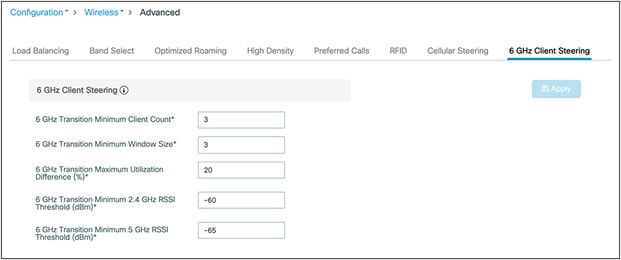
Configuring thresholds for 6 GHz Client Steering
Dual 5 GHz in the Catalyst CW9166D1

Dual 5Ghz Capability on Catalyst 9166D1
The Catalyst CW9166I has the flexibility to operate in a tri-band mode for client serving, that is, 2.4, 5, and 6 GHz, or to operate in 2.4, 5, and 5 GHz (dual 5 GHz) using the XOR radio capability under the following circumstances:
● For countries where 6-GHz spectrum is not yet available for use of Wi-Fi.
● In wireless networks, where 6-GHz client density is very minimal, and most clients are still 5 GHz.
The Flexible Radio Assignment (FRA) algorithm in RRM has the capability to dynamically convert the 6-GHz radio to a 5-GHz radio when either of the above criteria are met, or to revert to 6-GHz operation when it sees more 6-GHz-capable clients joining the AP.
Note: This is not the legacy FRA available in AireOS and Catalyst 9800 Wireless LAN Controller for 2.4 and 5 GHz.
The Catalyst CW9166D1, when operated as dual 5 GHz, offers two independent macro-macro directional cells, but focused in the same direction even though it’s an internal-antenna AP, which creates the simplicity of this feature. The two cells are band locked. The 5 GHz in slot 1 operates only in the UNII1 and 2 bands – that is, channels 36 to 64, and the XOR radio in slot 2, when operated in 5 GHz, is locked to the UNII2E and 3 bands – that is, channels 100 to 165.
Note: This restriction of band lock applies only when the access point is operating as dual 5 GHz.
The RRM algorithm runs independently on both radios and assigns the best channel and transmit power that it comes up with.
The decision to change the band is based on two parameters, Client Density and Channel Utilization. By default, the FRA runs every 1 hour. Unlike legacy FRA, the decision to change the band is based not on a single decision, but on a collective decision over several intervals. This is done to avoid frequent changes of radios and the resulting disruptions to client connectivity.
The WLC has the capability to maintain the snapshot of every run for a period of 1 week. – for a total of 168 intervals. As an example, if 10% of FRA decisions favor 5 GHz, the radio will be changed to 5 GHz, and if 90% favor 6 GHz, the radio will be changed to 6 GHz.
To enable FRA, navigate to Configuration > Radio Configurations > RRM > FRA and toggle FRA Status to “Enabled” in 5/6 GHz Flexible Radio Assignment.

Enabling 5/6 GHz FRA
It is recommended to leave the FRA Interval and thresholds at the defaults. However, these thresholds are configurable.
To configure the FRA Interval, select the FRA Interval from the pull-down menu. The minimum is 1 hour and is the default value, and the maximum is 24 hours. We recommend leaving the FRA Interval at 1 hour.
To change the threshold parameters, navigate to Configuration >Tags and Profiles > RF/Radio > RF > RF Profile and change the Client Reset Count and Client Utilization Threshold. Client Reset Count indicates the number of 6-GHz-capable clients appearing on the AP, and Client Utilization Threshold indicates the load. If the threshold is above the configured parameter in an interval, the interval is marked as 6 GHz favorable. A similar configuration is available for 5-GHz threshold parameters.
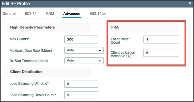
FRA threshold configuration
Note:
The 5-GHz threshold configuration can be made from the Configuration > RRM > FRA page; change the Client Select and Client Reset in 2.4/5 GHz Flexible Radio Assignment.
Important points
Whenever the Catalyst 9166D1 changes the XOR radio in slot 2 from 6 to 5 GHz and vice versa, the radios in slot 0 (2.4 GHz) and slot 1 (5 GHz) get reset as well, resulting in client disconnect in all three radios. Due to this issue, and to avoid disruptions in service, band change based on an FRA decision will be skipped when:
● The AP is serving 10 or more clients overall in any band.
● the Load on the AP is greater than 10%.
The 6-GHz radio in the Catalyst CW9166D1 can also be manually converted to a 5-GHz radio. To do so, navigate to Configuration > Wireless > Access Points > Dual-Band Radios.

Viewing the 9166D1 5/6-GHz dual-band radio
Click on the AP that you want to convert to dual 5-GHz mode. Under Role Assignment, choose Client Serving. From the Band Selection drop-down menu, select 5 GHz and click Update and Apply to Device to apply the configuration to the access point.

Manual configuration of 5/6-GHz dual band in the Catalyst CW9166D1
When deploying APs, one wireless design consideration is roaming, or how wireless clients can seamlessly move from one AP to another when they physically change locations. The main thing to keep in mind is the need to support clients that do not support WPA3 or Wi-Fi 6E. In such a scenario, clients that are currently on a 2.4- or 5-GHz band will not be able to roam to areas that contain only 6 GHz. Therefore, when designing your network, you may want to ensure that every access point is still broadcasting legacy bands with legacy security methods to ensure that there are no coverage holes for those wireless clients.
A wide variety of Wi-Fi 6E client devices are available now in the market. We recommend updating the client devices to the latest firmware driver. We also recommend updating the BIOS, in case the Wi-Fi 6E-capable laptop does not see the 6-GHz SSID.
When a Wi-Fi 6E client associates with the Catalyst CW9166D1 access point, you will be able to verify that it’s associated as a Wi-Fi 6E client by navigating to Monitoring > Wireless > Clients > [Select Wi-Fi 6E client] > 360 View.
In the figure below, the data next to Capabilities reads 802.11ax – 6 GHz, indicating that the wireless client is associated with the Wi-Fi 6E network.

Wi-Fi 6E wireless client metadata
Migration between management modes
The Catalyst CW9166D1 can convert from the Cisco Catalyst management mode to the Meraki management mode and vice versa. This converged hardware gives you the flexibility of on-premises or cloud management. It also provides investment protection for the future in case you want to switch between the two management options or between the Cisco Catalyst management mode and Meraki management mode at a later time.
Within the hardware itself, there are two boot partitions. The Cisco Catalyst partition will have the Cisco Catalyst image, and the Meraki partition will contain the Meraki image. Within the device there are three saved configurations, one for each management mode and one shared configuration that is used during the conversion.
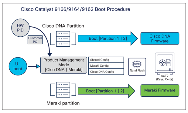
Catalyst 9166D1 boot procedure
Two serial numbers are provided on the access point. The Meraki serial number is vertically aligned and is used for any processes related to the Meraki management mode, such as claiming the device to a Meraki Dashboard account. The Cisco Catalyst serial number is horizontally aligned and is used for any processes related to the Cisco Catalyst management mode, such as Plug and Play using a Cisco Smart Account.
The following figure depicts the product information provided on the back of the access point.

Dual serial numbers on the Catalyst CW9166D1 are similar to the CW9166I pictured above
There are different regulatory domains based on the specific country in which you want to use the Catalyst CW9162I, CW9164I, or CW9166I. When purchasing in the Cisco Catalyst management mode, use the correct SKU when ordering.
Table 7. Regulatory domain SKUs
| Cisco Catalyst management mode SKUs |
Country/region |
| -A domain |
Canada |
| -B domain |
United States and Puerto Rico |
| -E domain |
Europe |
| -F domain |
Indonesia |
| -Q domain |
Japan |
| -R domain |
Russia |
| -Z domain |
Australia and New Zealand |
| -ROW domain |
Rest of the world |
To see a specific country’s compliance regulatory domains for the Catalyst CW9166D1, please visit the wireless compliance tool: https://www.cisco.com/c/dam/assets/prod/wireless/wireless-compliance-tool/index.html.
In Meraki, there are no specific country SKUs; there is only an -MR SKU. The access point in Meraki will automatically detect the country where the access point is currently functioning when connected to Meraki Dashboard.
Cisco Catalyst management mode to Meraki management mode
The conversion process from the Cisco Catalyst management mode to the Meraki management mode can be done from the Catalyst 9800 wireless controller.
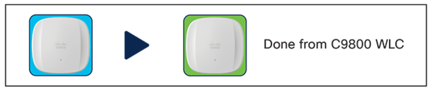
Conversion overview from Cisco Catalyst management mode to Meraki management mode
The following are the steps to perform the conversion process:
1. First, go to Migrate to Meraki Management Mode on the Wireless Controller

Cisco Catalyst to Meraki Conversion – Workflow, step 1
2. Then select the APs you want to convert to the Meraki management mode and click Migrate to Meraki Management Mode
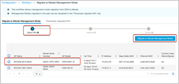
Select APs to convert to the Meraki management mode.
3. The controller will then validate the APs and you can select Next
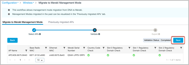
Conversion to Meraki management mode – Validation
4. Confirm the change on the selected Access Points
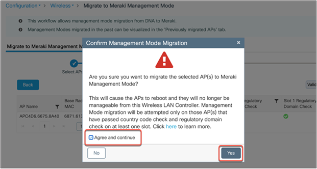
Conversion to Meraki management mode – Validation
5. Lastly, note down the Meraki Serial Number or click export the Access Points

Conversion to Meraki management mode – Status
There are flexible options for exporting the AP information that is used to claim the device on Meraki Dashboard.

Export conversion data to Meraki Dashboard
The figure below depicts converted APs on Meraki Dashboard.

AP status in Meraki Dashboard after conversion
Meraki management mode to Cisco management mode
Contact Meraki Support to migrate from Meraki management mode to Cisco management mode.
When converting from Cisco management mode to Meraki management mode, keep these two regulatory considerations in mind:
1. Make sure to set -ROW Access Point countries in the AP join profile and as a global configuration to properly migrate to the correct country.
a. Example: -ROW with AP join profile and global set to US. During migration, the country is set as AE.
2. The controller will match the regulatory domain of the access point and global AP countries when using multiple different regulatory domains in the global settings.
a Example 1: -E with AP join profile US and Global config set as US and France. During migration, the country is set as FR.
b. Example 2: -B AP with AP profile as France and Global config set as US and France. During migration, the country is set as US.
Cisco CleanAir Pro and the AI/ML-driven scanning radio
Wi-Fi 6E (6 GHz) was introduced with the Catalyst 9136I, and with it came new challenges for RF visibility and much more spectrum to monitor. In the past, the Catalyst 9100 APs relied on Cisco CleanAir® (software) and the RF-ASIC (hardware) for features such as packet capture, spectrum analysis, interference detection, and rogue and wireless intrusion prevention system (WIPS) detection. CleanAir and the RF-ASIC were great for RF visibility for the 2.4- and 5-GHz bands; however, with 6 GHz, Cisco CleanAir Pro and the AI/ML-driven scanning radio are being introduced to increase the performance and granularity required to manage this new spectrum (all 1200 MHz of it).
CleanAir Pro is software designed specifically for 6 GHz and the all-new challenges that have come with the introduction of 1200 MHz of spectrum. While many features work in conjunction with the AI/ML-driven scanning radio, CleanAir Pro also works with the Catalyst 9611D1 APs’ serving radios. Unlike previous generations of APs, CleanAir Pro can even decode high-efficiency (HE, 802.11ax) frames, which is crucial since Wi-Fi 6E uses only HE frames. In the future, there will even be an ML-based interferer classification built directly into the AP software for more efficient interferer analysis, rather than loading the WLC or Cisco Catalyst Center.

High-level comparison of CleanAir Pro and CleanAir
Cisco Catalyst Center and Wi-Fi 6E
Cisco Catalyst Center is Cisco’s network monitoring software, for everything related to analytics. With the introduction of Wi-Fi 6E, Cisco Catalyst Center Release 2.3.2 will support 6 GHz from all perspectives. This includes the Wi-Fi 6E dashboard, Intelligent Capture for packet capture and spectrum analysis on 6 GHz, rogue and aWIPS detection on 6 GHz, and many others.
The following are a few examples of the features on Cisco Catalyst Center related to Wi-Fi 6E.
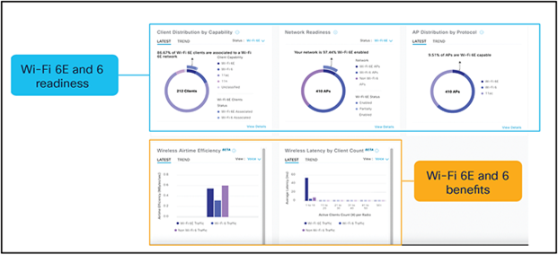
Wi-Fi 6/6E dashboard: View network readiness and benefits for Wi-Fi 6/6E

Spectrum analysis: Visualize RF spectrum energy, not only for 2.4-, 5-, and 6-GHz bands.
Spectrum analysis is part of the Intelligent Capture feature set.
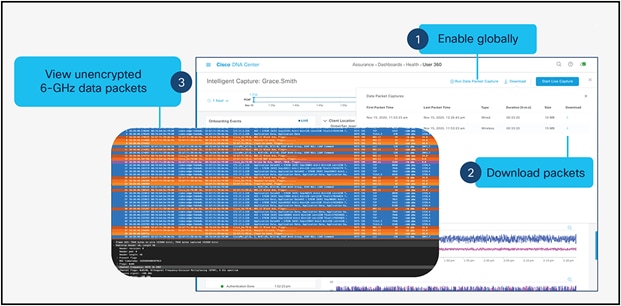
Data packet capture: Capture unencrypted data packets.
Data packet capture is part of the Intelligent Capture feature set.
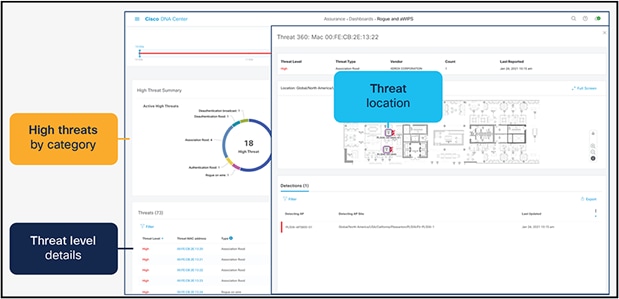
Rogue management and aWIPS: Detects wireless threats in the environment, not only for 2.4 and 5 GHz, but now also for 6 GHz.
Rogue management and aWIPS dashboard
Note:
● Refer to the “Software Solution Compatibility” section in this guide for the exact features released with Cisco IOS XE 17.9.1 and Cisco Catalyst Center 2.3.4.
● Please refer to the Cisco Catalyst Center user guide for a detailed overview.
Internet of Things integration
Environmental sensors and IoT Services with Cisco Spaces
The Catalyst CW9166D1 has three built-in environmental sensors, air quality, humidity, and temperature, that will be integrated with Cisco Spaces’ rich map. This integration will provide an immersive experience for facility managers to help ensure a safe working environment, especially geared toward back-to-office safety use cases.
The figure below depicts the details of the three environmental sensors built into the Catalyst CW9166D1

Overview of environmental sensors on the Catalyst 9166D1
Note:
● The support for environmental sensors is available starting with Cisco IOS XE Release 17.9.1.
● The area where the sensors are located is separated from the rest of the AP’s internal circuitry.
The figure below depicts the environmental sensor data in Cisco Spaces on a particular access point.

Environmental sensor data in Cisco Spaces
The figure below depicts how environmental sensor data is sent from the Catalyst CW9166I and CW9166D1 to Cisco Spaces.

Environmental sensor on Catalyst 9166D1 topology
The Catalyst CW9166D1 have a built-in IoT radio that can be used in conjunction with the IoT Services platform service in Cisco Spaces. IoT Services is designed to enable management of Internet of Things (IoT) devices across vendors, form factors, and technology protocols.
Within IoT Services, you can enable a Catalyst CW9166D1 to be in Scan mode or Transmit mode. In Transmit mode, the AP can broadcast iBeacon, Eddystone URL, and Eddystone UID profiles. While in Scan mode, the AP can scan the vicinity for other BLE devices and receive telemetry data from floor beacons, which can be decoded in Cisco Spaces.
The Catalyst CW9166D1 can manage and configure wireless IoT devices if you enable the Advanced AP Gateway feature, which installs a Cisco IOx application on the access point. This saves the user the trouble of having several gateways across different vendors.

Capabilities of the built-in IoT radio on the Catalyst CW9166D1
The figure below depicts the telemetry data received from a BLE device that is decoded in Cisco Spaces.

BLE telemetry data on Cisco Spaces
The figure below depicts how BLE data is sent from the Catalyst CW9166D1 to Cisco Spaces.

IoT radio on the Catalyst CW9166D1 topology
Both the environmental sensors and IoT radio require Cisco Spaces and IoT Services to be configured. Please use the following guides for configuring Cisco Spaces and IoT Services.
https://www.cisco.com/c/en/us/td/docs/wireless/cisco-dna-spaces/iot-services/b_iot_services.html
To enable the IoT radio or environmental sensors in Cisco Spaces, go to the specific access point in IoT Services in Cisco Spaces and select the feature to turn on or bulk-enable each feature in the AP Beacons page.
The figures below depict how to enable or disable the IoT radio or environmental sensors on Cisco Spaces through a specific access point.
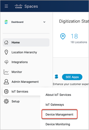
Cisco Spaces IoT Services
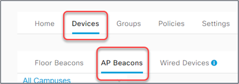
Cisco Spaces AP Beacons within IoT Services

IoT Services AP profiles

Enabling sensor or BLE functionality on the Catalyst CW9166D1 in Cisco Spaces
The figures below depict how to bulk-enable or disable the IoT radio or environmental sensors in Cisco Spaces on the AP Beacons page.
Cisco Spaces IoT Services
Cisco Spaces AP Beacons within IoT Services

Cisco Spaces bulk-enable or disable of BLE or sensor capabilities.
The figure below depicts the Cisco Spaces Smart Workspaces application and how the environmental sensor data and BLE IoT integration would be used within the application.
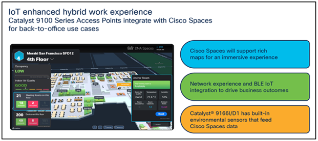
Cisco Spaces Smart Workspaces
To learn more about Smart Workspaces or to request a demo, visit https://dnaspaces.cisco.com/smart-workspaces/.
Environmental sensors and IoT radio without Cisco Spaces
Users can utilize model-driven telemetry to subscribe to environmental sensor data on the Catalyst CW9166I and subscribe to BLE device data that is captured from the Catalyst 9666D1 access points via YANG with gRPC, gNMI, or NETCONF.
The environmental sensors and IoT radio can be turned on manually on the access point through the wireless controller via the AP join profile. A user can create IETF telemetry subscriptions in the WLC to send telemetry data to a receiver such as Telegraf. The receiver will then be able to get the environmental sensor data or BLE device data from the WLC and send that data to the appropriate forums for use.
The figure below depicts how BLE data is sent from the Catalyst CW9166D1 to a wireless controller and then to an administrator.

Model-driven telemetry
The figure below depicts an example of how to create an IETF telemetry subscription on the wireless controller.
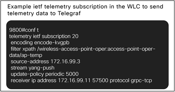
Wireless controller IETF telemetry subscription example
Here is a breakdown of what these commands are doing in the figure above:
telemetry ietf subscription 20: This is the subscription ID that groups together all the config to stream one set of data.
encoding encode-kvgpb: This matches the encoding specified inside “cisco_telemetry_mdt” that is used by the receiver. KVGPB stands for Key Value Google Protocol Buffer.
filter xpath /wireless-access-point-oper:access-point-oper-data/ap-temp: This is the data we want to send; it is the xpath for the AP temperature data.
source-address 172.16.99.3: This is where we want to send the data from, that is, the wireless controller’s management interface.
stream yang-push: Stream the data using YANG.
update-policy periodic 5000: Send new data every 5 seconds.
receiver ip address 172.16.99.3 57500 protocol grpc-tcp: Send the data to the receiver (172.16.99.3) on the port that receiver is listening on (TCP 57500) using grpc-tcp.
We can similarly create this subscription for other data coming from the wireless controller, including the air quality data and BLE data.
The figure below depicts how to enable the environmental sensors on an AP join profile.

Telemetry data AP profile configuration
Once the air quality and temperature sensor are enabled, the user can create IETF telemetry subscriptions pointing to their specific receiver and be able to get the raw data coming from the environmental sensors.
The xpath for the air quality data is: /wireless-access-point-oper:access-point-oper-data/ap-air-quality
The xpath for the temperature data is: wireless-access-point-oper:access-point-oper-data/ap-temp
The figure below depicts sample temperature data coming from the Catalyst 9800 wireless controller and collected from the Catalyst 9166I environmental sensor.

Temperature telemetry data output
The figure below depicts sample air quality data coming from the Catalyst 9800 wireless controller and collected from the Catalyst CW9166D1 environmental sensor.
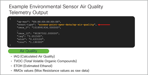
Air quality telemetry data output
The figure below depicts how to enable the BLE radio on a wireless controller.
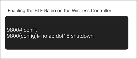
Enabling the BLE radio on the wireless controller
Once the BLE radio is enabled on the wireless controller and the access point, the user can create IETF telemetry subscriptions pointing to their specific receiver and be able to get the raw data coming from the surrounding BLE sensors that are scanned by the access point’s BLE radio.
The xpath for the BLE data is: wireless-ble-ltx-oper:ble-ltx-oper-data/ble-ltx-ap-streaming.
The figure below depicts sample BLE data coming from the Catalyst 9800 wireless controller and collected from the Catalyst CW9166D1 IoT radio.
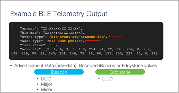
BLE telemetry data output
For more information on programmability and model-driven telemetry, refer to the configuration guide: https://www.cisco.com/c/en/us/td/docs/ios-xml/ios/prog/configuration/178/b_178_programmability_cg/m_178_prog_ietf_telemetry.html.
Enterprise wireless IoT with application hosting
The Catalyst CW9166D1 allow users to load Cisco IOx applications onto the platform to solve IoT use cases by acting as an IoT gateway. These IOx applications can communicate with an RF-USB dongle connected to the USB port of the AP and talk to the surrounding IoT devices. IoT device data is then sent through the AP and to a back-end server. With the Catalyst CW9166D1, the USB port outputs a total of 4.5 watts of power.
Use cases for application hosting include retail management with electronic shelf labels, asset management with environmental sensors and real-time location, and medical management with tracking of patient vitals.
The figure below depicts the basic topology of application hosting with the Catalyst CW9166D1.
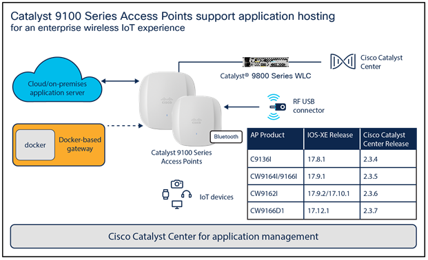
Application hosting
Support for the IOx framework on the Catalyst CW9166D1 is available starting with Cisco IOS XE Release 17.12.1 and Cisco Catalyst Center Release 2.3.7.
For more information on application hosting, refer to the deployment guide: https://www.cisco.com/c/en/us/products/collateral/wireless/access-points/guide-c07-744305.html.
The Cisco Catalyst 9166D1 has support for a new mode called Site Survey. The purpose of this mode is to allow users to conduct wireless site survey testing using a single access point, including understanding RF propagation, client join metrics, and so on, without the need for a controller. This mode converts the AP into a limited standalone mode, enabling it to broadcast 2.4-, 5-, and 6-GHz SSIDs. Site Survey mode provides all the control needed to configure and conduct a site survey while reducing the additional equipment required to a power source (battery or PoE switch port). It lets users bring the AP into any environment with either a power source or battery backup and conduct a site survey test.
When the Catalyst CW9166D1 is in Site Survey mode, you will be able to access the AP’s WebUI for each configuration and view various RF metrics for RF coverage and planning.
These configurations include channel number, channel width, Tx power, SSID, and data rates.
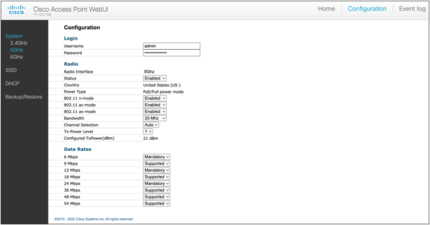
Configuration page of the Catalyst CW9166D1 in Site Survey mode
The steps below describe how to convert a Catalyst 9166D1 AP into Site Survey mode:
1. Change the AP to Site Survey mode (Run command on the AP’s CLI): ap-type site-survey
2. After booting up, the AP is automatically assigned a static IP of 10.0.23.1.
3. The AP will start broadcasting the C9166_site_survey SSID.
4. Connect your wireless client with the C9166_site_survey SSID and it will receive an IP from 10.0.23.0/24.
5. Access the AP’s Site Survey WebUI via 10.0.23.1.
6. The first time, the default username and password are admin/admin. You will be directed to reset that insecure password on the first login.
7. When done, convert your AP back to CAPWAP mode to join the controller again (AP CLI): ap-type capwap
If an AP is converted to Site Survey mode while connected to a WLC, it will disjoin and go into standalone mode. s
Software solution compatibility
This section lists the software features and their versions compatible with the Cisco Catalyst 9166D1 access points.
Table 8. Software support matrix
| Access points |
Cisco IOS XE |
AireOS |
Cisco Catalyst Center |
Cisco Prime |
CMX |
Cisco Spaces Connector |
ISE |
| Catalyst CW9166D1 |
17.12.1 |
– |
2.3.7 |
NA |
11.0.0-154 |
3.0 (May 2023) |
2.6 and above |
Table 9. Cisco Catalyst 9166D1 feature release timelines
| Feature |
Cisco IOS XE version |
Cisco Catalyst Center version |
Cisco Spaces Connector version |
Meraki |
Notes |
| FRA: Dual 4x4:4SS 5-GHz radios |
17.12.1 |
– |
– |
Flex Radio |
Applicable only to Catalyst 9166D1 (and MR57 for Meraki) |
| Temperature, humidity, air quality sensors |
17.12.1 |
– |
3.0 (May 2023) |
MT Series* |
*Discrete sensors in Meraki |
| CleanAir Pro/Spectrum Analysis (Intelligent Capture) |
17.12.1 |
2.3.7 |
– |
Spectrum Analyzer/ Packet Capture (PCAP) |
No anomaly PCAP support available in Meraki management mode |
| Rogue management with AI/ML-driven scan radio |
17.12.1 |
2.3.7 |
– |
Air Marshal |
|
| aWIPS with AI/ML-driven scan radio |
17.12.1 |
2.3.7 |
– |
Air Marshal |
|
| Application hosting |
17.12.1 |
2.3.7 |
– |
–* |
*USB support available for select partners |
| FastLocate |
17.12.1 |
– |
3.0 (May 2023) |
Location Analytics |
|
| BLE |
17.12.1 |
– |
3.0 (May 2023) |
Scanning API/MQTT |
|
| Zero-Wait Dynamic Frequency Selection |
Roadmap |
– |
– |
– |
|
| AI-Enhanced RRM (6 GHz) |
17.12.1 |
2.3.7 |
– |
Auto RF |
|
| Mesh |
Roadmap |
Roadmap |
– |
Yes (indoor mesh*) |
Meraki Mesh is the default mesh for the Meraki management mode |
| Work Group Bridge |
Roadmap |
– |
– |
– |
Table 10. Wireless Assurance compatibility matrix for the Catalyst 9166D1
| Feature |
Cisco Catalyst Center |
WLC hardware |
WLC software |
AP modes |
| Network Assurance |
2.3.7 |
AireOS |
– |
– |
| Cisco IOS XE |
17.12.1 |
Local, Cisco FlexConnect®, fabric |
||
| Application Experience |
2.3.7 |
AireOS |
– |
– |
| Cisco IOS XE |
17.12.1 |
Local (FlexConnect and fabric support are on roadmap) |
||
| Application Visibility |
2.3.7 |
AireOS |
– |
– |
| Cisco IOS XE |
17.12.1 |
Local, FlexConnect, fabric |
||
| Rogue (with CleanAir) |
2.3.7 |
AireOS |
– |
– |
| Cisco IOS XE |
17.12.1 |
Local, FlexConnect, fabric |
||
| aWIPS (with CleanAir) |
2.3.7 |
AireOS |
– |
– |
| Cisco IOS XE |
17.12.1 |
Local, FlexConnect, fabric |
||
| Wi-Fi 6 dashboard |
2.3.7 |
AireOS |
– |
– |
| Cisco IOS XE |
17.12.1 |
Local, FlexConnect, fabric |
||
| Wireless Network Service Analytics |
2.3.7 |
AireOS |
– |
– |
| Cisco IOS XE |
17.12.1 |
Local, FlexConnect, fabric |
||
| Wireless 3D maps |
Roadmap |
AireOS |
– |
Local, FlexConnect, fabric |
| Cisco IOS XE |
17.12.1 |
Local, FlexConnect, fabric |
||
| True Trace |
2.3.7 |
AireOS |
– |
Local, FlexConnect, fabric |
| Cisco IOS XE |
17.12.1 |
Local, FlexConnect, fabric |
||
| Webex® 360 |
2.3.7 |
AireOS |
– |
Local, FlexConnect, fabric |
| Cisco IOS XE |
17.12.1 |
Local, FlexConnect, fabric |
Table 11. AI Network Analytics compatibility matrix for the Catalyst CW9166D1
| Feature |
WLC hardware |
WLC software |
Cisco Catalyst Center |
AP modes |
| AI-driven issues |
AireOS |
– |
– |
Local, FlexConnect, fabric |
| Cisco IOS XE |
17.12.1 |
2.3.7 |
||
| Network Insights |
AireOS |
– |
– |
|
| Cisco IOS XE |
17.12.1 |
2.3.7 |
||
| Heatmaps |
AireOS |
– |
– |
|
| Cisco IOS XE |
17.12.1 |
2.3.7 |
||
| Peer Comparison |
AireOS |
– |
– |
|
| Cisco IOS XE |
17.12.1 |
2.3.7 |
||
| Network Comparison (previously called Site Comparison) |
AireOS |
– |
– |
|
| Cisco IOS XE |
17.12.1 |
2.3.7 |
||
| AI-driven baselines |
AireOS |
– |
– |
|
| Cisco IOS XE |
17.12.1 |
2.3.7 |
Table 12. Client Analytics compatibility matrix for the Catalyst CW9166D1
| Feature |
Cisco Catalyst Center |
WLC |
Software version |
| Apple Analytics |
2.3.7 |
AireOS |
– |
| Cisco IOS XE |
17.12.1 |
||
| Samsung Analytics |
2.3.7 |
AireOS |
– |
| Cisco IOS XE |
17.12.1 |
||
| Intel® Connectivity Analytics |
Roadmap |
AireOS |
– |
| Cisco IOS XE |
17.12.1 |
Table 13. Intelligent Capture compatibility matrix for the Catalyst CW9166D1
| Feature |
Cisco Catalyst Center |
WLC |
Software version |
| Anomaly PCAP Scheduled PCAP AP and client statistics |
2.3.7 |
AireOS |
– |
| Cisco IOS XE |
17.12.1 |
||
| Data PCAP |
2.3.7 |
AireOS |
– |
| Cisco IOS XE |
17.12.1 |
||
| Spectrum Analysis |
2.3.7 |
AireOS |
– |
| IOS XE |
17.12.1 |
Table 14. Wireless automation compatibility matrix for the Catalyst CW9166D1
| Feature |
Cisco Catalyst Center |
WLC hardware |
WLC software |
AP modes |
| Wireless provisioning |
2.3.7 |
AireOS |
– |
Local, FlexConnect, fabric AP modes |
| Cisco IOS XE |
17.12.1 |
|||
| Cisco Umbrella® |
2.3.7 |
AireOS |
– |
|
| Cisco IOS XE |
17.12.1 |
|||
| Cloud Device Provisioning application |
2.3.7 |
AireOS |
– |
|
| Cisco IOS XE |
17.12.1 |
|||
| SD-Access |
2.3.7 |
AireOS |
– |
|
| Cisco IOS XE |
17.12.1 |
|||
| Wide Area Bonjour |
2.3.7 |
AireOS |
– |
|
| Cisco IOS XE |
17.12.1 |
|||
| User Defined Network |
2.3.7 |
AireOS |
– |
|
| Cisco IOS XE |
17.12.1 |
|||
| Command Runner |
2.3.7 |
AireOS |
– |
|
| Cisco IOS XE |
17.12.1 |
|||
| AP Plug and Play |
2.3.7 |
AireOS |
– |
|
| Cisco IOS XE |
17.12.1 |
|||
| Software Image Management (SWIM) |
2.3.7 |
AireOS |
– |
|
| Cisco IOS XE |
17.12.1 |
|||
| Cisco Secure Network Analytics |
Roadmap |
AireOS |
– |
|
| Cisco IOS XE |
17.12.1 |
|||
| Application hosting |
2.3.7 |
AireOS |
– |
|
| Cisco IOS XE |
17.12.1 |
|||
| Application policy |
2.3.7 |
AireOS |
– |
|
| Cisco IOS XE |
17.12.1 |
|||
| Ekahau integration |
AireOS |
– |
||
| Cisco IOS XE |
17.12.1 |
|||
| Security advisories |
2.3.7 |
AireOS |
– |
|
| Cisco IOS XE |
17.12.1 |
Table 15. Policy application compatibility matrix for the Catalyst CW9166D1
| Feature |
Cisco Catalyst Center |
WLC hardware |
WLC software |
AP modes |
| Group-Based Access Control |
2.3.7 |
AireOS |
– |
Local, FlexConnect, fabric |
| Cisco IOS XE |
17.12.1 |
|||
| AI Endpoint Analytics |
2.3.7 |
AireOS |
– |
|
| Cisco IOS XE |
17.12.1 |
|||
| Group-Based Policy Analytics |
2.3.7 |
AireOS |
– |
|
| Cisco IOS XE |
17.12.1 |
|||
| Policy Analytics Dashboard |
2.3.7 |
AireOS |
– |
|
| Cisco IOS XE |
17.12.1 |
Table 16. Cisco Spaces compatibility matrix for the Catalyst 9166D1
| Feature |
Cisco Spaces Connector |
Cisco Prime |
Cisco Catalyst Center |
WLC hardware |
WLC software |
Meraki |
AP modes |
| Wi-Fi location |
3.0 (May 2023) |
- |
2.3.7 |
AireOS |
– |
Yes |
Local, FlexConnect, fabric |
| Cisco IOS XE |
17.12.1 |
||||||
| FastLocate |
3.0 (May 2023) |
- |
2.3.7 |
AireOS |
– |
Yes |
|
| Cisco IOS XE |
17.12.1 |
||||||
| BLE location |
3.0 (May 2023) |
- |
2.3.7 |
AireOS |
– |
Yes |
|
| Cisco IOS XE |
17.12.1 |
||||||
| BLE management |
3.0 (May 2023) |
– |
– |
AireOS |
– |
Yes |
|
| Cisco IOS XE |
17.12.1 |
||||||
| Concurrent BLE scan and transmit |
3.0 (May 2023) |
– |
– |
AireOS |
– |
– |
|
| Cisco IOS XE |
17.12.1 |
||||||
| IoT sensors |
3.0 (May 2023) |
– |
– |
AireOS |
– |
MT Series |
|
| Cisco IOS XE |
17.12.1 |
||||||
| Analytic applications (Behavior Metrics, Location Analytics, Right Now, Impact Analysis |
3.0 (May 2023) |
– |
– |
AireOS |
– |
Analytic applications |
|
| Cisco IOS XE |
17.12.1 |
||||||
| Proximity Reporting |
3.0 (May 2023) |
– |
– |
AireOS |
– |
Location Analytics |
|
| Cisco IOS XE |
17.12.1 |
||||||
| OpenRoaming |
3.0 (May 2023) |
- |
2.3.7 |
AireOS |
- |
OpenRoaming |
|
| Cisco IOS XE |
17.12.1 |
||||||
| Detect and Locate |
3.0 (May 2023) |
- |
2.3.7 |
AireOS |
– |
Location heatmap |
|
| Cisco IOS XE |
17.12.1 |
||||||
| Captive portals |
3.0 (May 2023) |
- |
2.3.7 |
AireOS |
– |
||
| Cisco IOS XE |
17.12.1 |
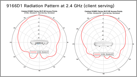
CW9166D1 – 2.4 GHz Client Serving Radio (Slot-0)
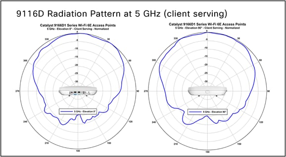
CW9166D1 – 5 GHz Client Serving Radio (Slot-1)

CW9166D1 – 5 GHz client Serving Radio (Slot-2)

CW9166D1 – 6 GHz client Serving Radio (Slot-2)

CW9166D1 – 2.4 GHz AI/ML-Driven Scanning Radio
CW9166D1 – Patter n compared against Cisco AIR-ANT2566P4W-RS

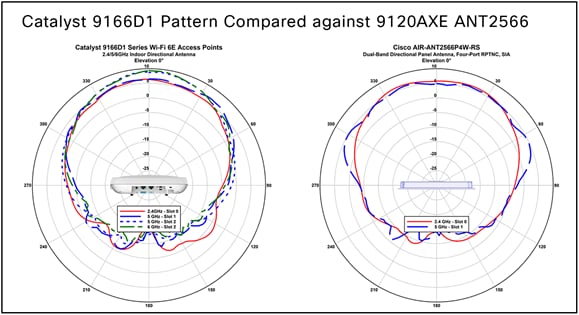
CW9166D1 – Pattern compared against Cisco 9120AXE with ANT2566P4W

CW9166D1 – Pattern compared against Cisco C-ANT9103
● Catalyst 9166 Series data sheet
● Catalyst 9800 Deployment Guide