Cisco Embedded Wireless Controller on Catalyst Access Points (EWC) White Paper
Available Languages
Bias-Free Language
The documentation set for this product strives to use bias-free language. For the purposes of this documentation set, bias-free is defined as language that does not imply discrimination based on age, disability, gender, racial identity, ethnic identity, sexual orientation, socioeconomic status, and intersectionality. Exceptions may be present in the documentation due to language that is hardcoded in the user interfaces of the product software, language used based on RFP documentation, or language that is used by a referenced third-party product. Learn more about how Cisco is using Inclusive Language.
The Cisco Embedded Wireless Controller (EWC) on Catalyst Access Points is a software-based controller integrated into Cisco Catalyst 9100 Access Points. It is a simplified, low-cost, feature-rich Wi-Fi architecture with enterprise-level WLAN capability streamlined for small and midsize deployments. With this solution, small and midsize networks can enjoy the same quality user experiences as large enterprises.
In a Cisco EWC network, an Access Point (AP) running the wireless controller function is designated as the active AP. The other access points, which are managed by this active AP, are referred to as subordinate APs.
The active EWC has two roles:
● It functions and operates as a Wireless LAN Controller (WLC) to manage and control the subordinate APs. The subordinate APs operate as lightweight access points to serve clients.
● It operates as an access point to serve clients.
Supported Cisco access points
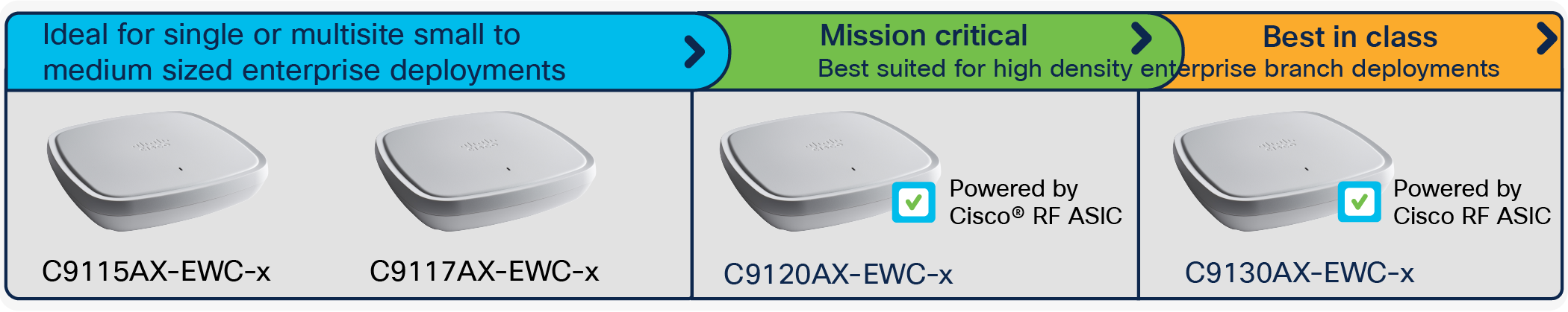
Access points for different deployments
The access points that support the EWC function are listed in the following table.
Table 1. Access points that support the EWC
| Access points supported as primary |
Supported model numbers |
Scale |
| Cisco Catalyst 9115AXI Access Point |
C9115AXI-EWC-X |
50 access points, 1000 clients |
| Cisco Catalyst 9115AXE Access Point |
C9115AXE-EWC-X |
50 access points, 1000 clients |
| Cisco Catalyst 9117AXI Access Point |
C9117AXI-EWC-X |
50 access points, 1000 clients |
| Cisco Catalyst 9120AXI Access Point |
C9120AXI-EWC-X |
100 access points, 2000 clients |
| Cisco Catalyst 9120AXE Access Point |
C9120AXE-EWC-X |
100 access points, 2000 clients |
| Cisco Catalyst 9120AXP Access Point |
C9120AXP-EWC-X |
100 access points, 2000 clients |
| Cisco Catalyst 9130AXI Access Point |
C9130AXI-EWC-X |
100 access points, 2000 clients |
| Cisco Catalyst 9130AXE Access Point |
C9130AXE-EWC-X |
100 access points, 2000 clients |
The access points that operate as subordinate APs are listed in the following table.
Table 2. Access points supported as subordinates
| Access points supported as subordinate APs |
Supported model numbers |
| Cisco Catalyst 9100 Series |
C9115AXI C9116AXE C9117AXI C9120AXI C9120AXE C9120AXP C9130AXI C9130AXE |
| Cisco Aironet 1800 Series |
AIR-AP1852I AIR-AP1852E AIR-AP1815I AIR-AP1815W AIR-AP1842I AIR-AP1810W |
| Cisco Aironet 2800 Series |
AIR-CAP2802I AIR-CAP2802E |
| Cisco Aironet 3800 Series |
AIR-CAP3802I AIR-CAP3802E |
| Cisco Aironet 4800 Series |
AIR-CAP4802I |
| Cisco Aironet 1540 Series |
AIR-CAP1540 |
| Cisco Aironet 1560 Series |
AIR-CAP1560 |
| Cisco Catalyst IW6300 Heavy Duty Series |
IW-6300H |
Software release numbers
Cisco EWC on Catalyst Access Points is supported beginning with Release 16.12.2s.
Interoperability
Cisco EWC can interoperate with the following:
● Cisco DNA Center 1.3.3 and later release
● Cisco Connected Mobile Experiences (CMX) 10.6, Cisco Spaces
● Cisco Identity Services Engine (ISE) 2.3, 2.4, 2.5 and later release
Ports
A port is a physical entity used to connect Cisco Catalyst 9100 Access Points to the network. Two RJ-45 ports are available on the 9100 access points:
● 1x 100, 1000, 2500, or 5000 Multigigabit Ethernet (RJ-45) – IEEE 802.3bz
● Management console port (RJ-45)
Interfaces
An interface is a logical entity on an EWC. The management interface must be configured and is used for in-band management: web UI, Telnet/SSH Command-Line Interface (CLI), or telemetry and programmable interface with NETCONF/YANG.
WLANs
A WLAN associates a Service Set Identifier (SSID) to VLANs. It is configured with the security type, Quality of Service (QoS), radio policies, and other wireless network parameters. On an EWC network, up to 16 WLANs can be configured. The WLANs can be mapped to VLANs trunked on the switch port.
Switch configuration
All access points, including the active AP in a EWC network, should be in the same Layer 2 broadcast domain.
The switch to which the access points connect has a configuration similar to the following:
vlan 10
name Employee
vlan 20
name Guest
vlan 122
name Management
interface Vlan10
description >> Employee Network <<
ip address 10.10.10.1 255.255.255.0
!
interface Vlan20
description >> Guest Network <<
ip address 20.20.20.1 255.255.255.0
!
interface Vlan122
description >> Management and EWC Network <<
ip address 172.20.229.2 255.255.255.0
interface GigabitEthernet1/0/37
description >> Connected to EWC AP<<
switchport trunk native vlan 122
switchport trunk allowed vlan 10,20,122
switchport mode trunk
Prerequisites for deploying the EWC
The prerequisites for deploying an EWC network are as follows:
● You must not have other Cisco wireless controllers, neither appliance nor virtual, in the same network, during the setup or daily operation of a Cisco EWC network.
● An EWC network is supported in the same Layer 2 domain.
● Configure a Dynamic Host Configuration Protocol (DHCP) server on the switch or externally so that Cisco Catalyst 9100 Access Points can obtain an IP address at bootup. The DHCP server also assigns IP addresses to other APs and wireless clients.
● The DHCP server should provide default gateway and DNS server IP addresses.
● If the network is made up of different AP models, you need to set a Trivial FTP (TFTP) server that can be accessed from the management interface of the EWC. Save the C9800-AP-univesalk9<version>.zip file (unzipped) on the TFTP server.
● Decide on the first AP to set up. This AP must support Cisco EWC functionality. You can also connect multiple Cisco Catalyst 9100 Access Points running the EWC to the switch.
● You will need a Wi-Fi-enabled laptop to connect to the predefined CiscoAirProvision-<last 4 digits of AP-MAC> SSID for provisioning and configuring the EWC. Alternatively, you can use a mobile device or tablet with the Cisco Catalyst Wireless application installed to configure and provision the EWC.
● If you intend to use 802.1X authentication, you need to have a RADIUS/Authentication, Authorization, and Accounting (AAA) server.
● All APs joining to EWC network should have minimum of 8.10.X or 16.12.X code.
Connecting an EWC-capable access point
To connect an EWC-capable access point to a 9100 access point, perform the following steps:
Step 1. Connect and power up the EWC-capable access point.
The switch port to which the 9100 access point is connected can be a trunk port or an access port. If multiple VLANs are being used for client traffic, the switch port should be configured to trunk the VLANs. Also note that management traffic is untagged, and if a VLAN is being used for management, it should be configured as a native VLAN on the switch port.
The following is an example of the switch port:
interface GigabitEthernet1/0/37
description » Connected to EWC AP «
switchport trunk native vlan 122
switchport trunk allowed vlan 10,20,122
switchport mode trunk
Step 2. Wait for approximately 5 minutes and observe the access point LED until it turns solid green and the access point starts to broadcast the CiscoAirprovision-<XXXX> SSID.
Day 0 – provisioning using the over-the-air setup wizard
To configure the EWC using the over-the-air setup wizard, perform the following steps:
Step 1. Connect a wireless client or laptop to CiscoAirprovision-<XXXX> SSID with PSK = password.
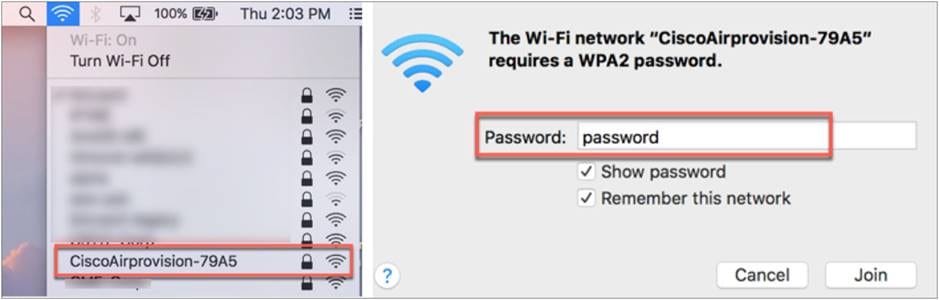
Note: If an external DHCP server is configured, the client should get an IP address from the DHCP server.
Step 2. Open the supported browser (Chrome, Firefox, Safari, or Edge), then browse to https://mywifi.cisco.com on the EWC web UI.
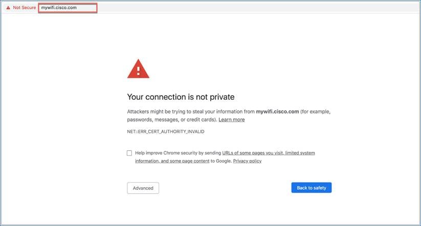
Note: The EWC uses a self-signed certificate for HTTPS. Therefore, when the certificate is presented to the browser, it will display a warning message and ask whether you wish to proceed with an exception. Accept the risk and proceed to access the EWC login page. Following is the list of supported browsers and operating systems.
Table 3. Supported browsers and operating systems
| Browser |
Version |
Operating System |
Status |
Workaround |
| Google Chrome |
77.0.3865.120 |
macOS Mojave Version 10.14.6 |
Works |
Proceed through the browser warning. |
| Safari |
13.0.2 |
macOS Mojave Version 10.14.6 |
Works |
Proceed through the browser warning. |
| Mozilla Firefox |
69.0.1 |
macOS Mojave Version 10.14.6 |
Works only if exception is added. |
Set the exception. |
| Mozilla Firefox |
69.0.3 |
macOS Mojave Version 10.14.6 |
Works only if exception is added. |
Set the exception. |
| Google Chrome |
77.0.3865.90 |
Windows 10 Version 1903 (OS Build 18362.267) |
Works |
Proceed through the browser warning. |
| Microsoft Edge |
44.18362.267.0 |
Windows 10 Version 1903 (OS Build 18362.267) |
Works |
Proceed through the browser warning. |
| Mozilla Firefox |
68.02 |
Windows 10 Version 1903 (OS Build 18362.267) |
Works |
Proceed through the browser warning. |
| Mozilla Firefox |
69.0.3 |
Windows 10 Version 1903 (OS Build 18362.267) |
Works only if exception is added. |
Set the exception. |
| Google Chrome |
78.0.3904.108 |
macOS Catalina 10.15.1 |
Does not work |
NA |
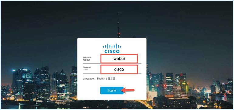
Step 3. Enter Username = webui and Password = cisco to log in to the EWC wizard.
Step 4. Configure the username and password. The country will be selected according to the AP regulatory domain.
Note: If the country code is incorrect, you can select from the drop-down list by clicking the +.
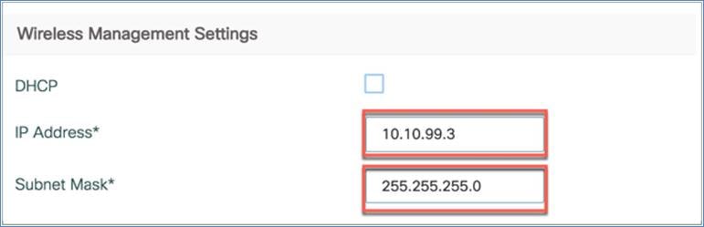
The wireless management IP address is set to the DHCP address by default. If required, you can configure it by unchecking the DHCP box.
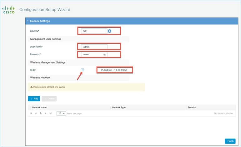
You can also manually assign the wireless management IP address by configuring the IP address and subnet mask as shown below.
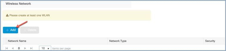
Step 5. The last step is to configure the wireless network by creating at least one WLAN. Click + Add to do this.
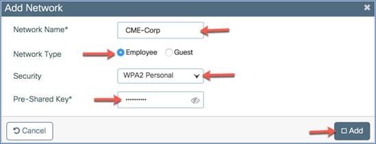
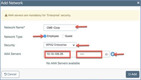
The Add Network dialog will appear so you can configure the WLAN settings. Assign the following:
Network name: This defines the network or WLAN/SSID name.
Network type: This can be an employee or guest WLAN. If you select Employee, there is an option to select the security type.
Security: This option defines the WLAN security type, such as WPA2 Personal (PSK/password authentication) or WPA2 Enterprise (802.1X with RADIUS authentication)
Click Add to create the WLAN.
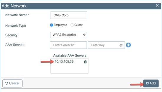
If you select WPA2 Enterprise as the security type, you will need to configure an AAA server.
Configure the AAA server IP address and shared secret and click the +. The assigned AAA server will appear in the list of available AAA servers. Click Add to configure the 802.1X-enabled WLAN.
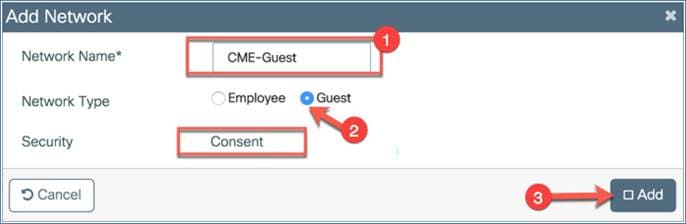
Adding a guest WLAN
Similarly, you can add a guest WLAN by clicking Add.

Assign the following:
Network name: This defines the network or WLAN/SSID name.
Network type: Choose the Guest option.
Security: The Consent option is chosen by default on day 0.
Click Add to create the WLAN.
Step 6. Verify the settings and then click Finish to push this configuration to the EWC. The dialog will pop up to inform you that CiscoAirprovision-<XXXX> SSID will be disabled and you need to connect to the configured employee SSIDs to manage the device. Click Yes if the configuration is correct and then, in the other information dialog, click OK.
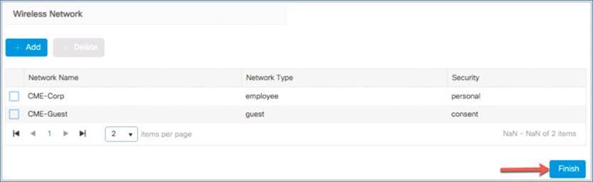
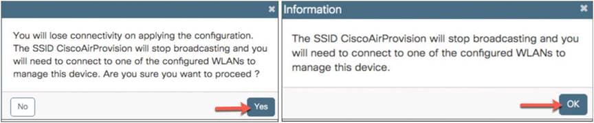
The access points will NOT reboot.
If required, you can also do SSH/CLI-based day-0 provisioning.
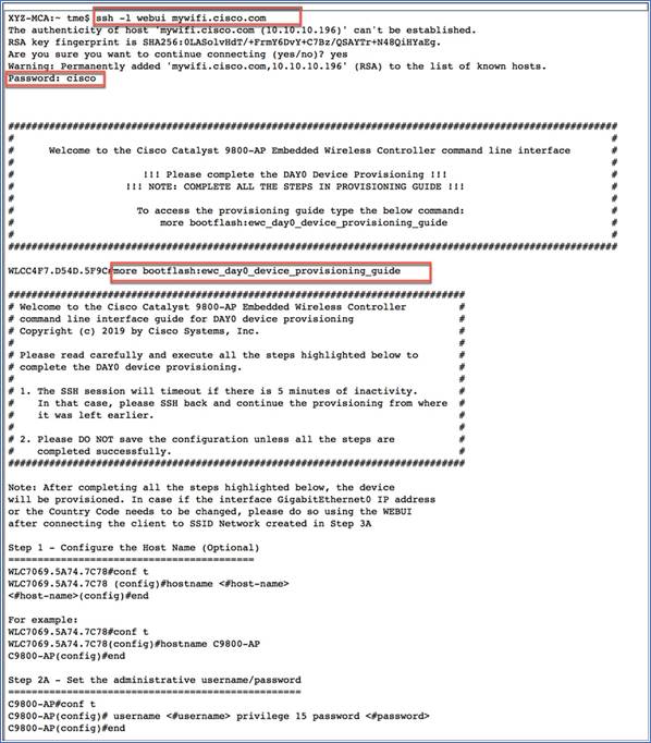
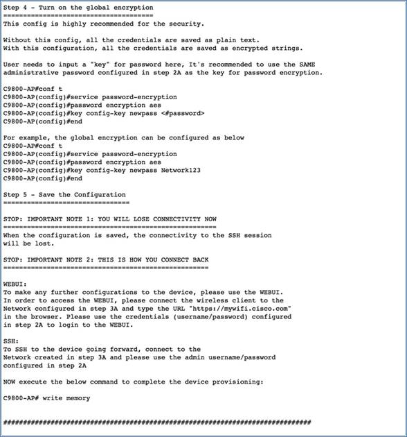
For SSH-based day-0 provisioning from a wireless client, follow these steps:
1. Connect a wireless client to the CiscoAirProvision-<XXXX> SSID.
2. You can SSH to the controller using ssh -l webui mywifi.cisco.com, with the password = cisco.
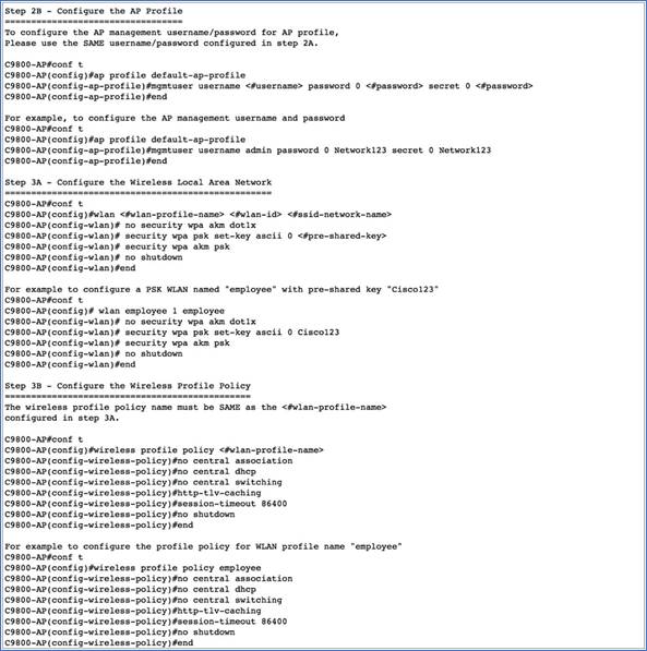
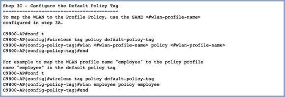
3. This will display the day-0 banner, which will point you to the day-0 device provisioning guide and the command to access it. Basically, the day-0 device provisioning guide will describe the sequence of steps to follow to complete the day-0 device provisioning, as shown below.
Logging in to the EWC
To log in to the EWC, perform the following steps:
Procedure
Step 1. Connect to the employee SSID that you created from the configuration wizard. Enter the URL https://mywifi.cisco.com in the web browser. The Cisco Catalyst EWC login page should appear.

Step 2. Enter the administrator username and password.
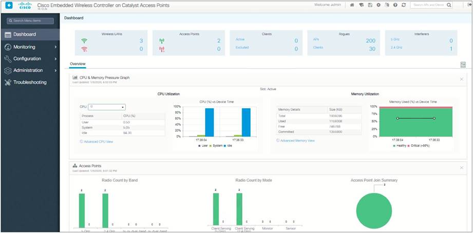
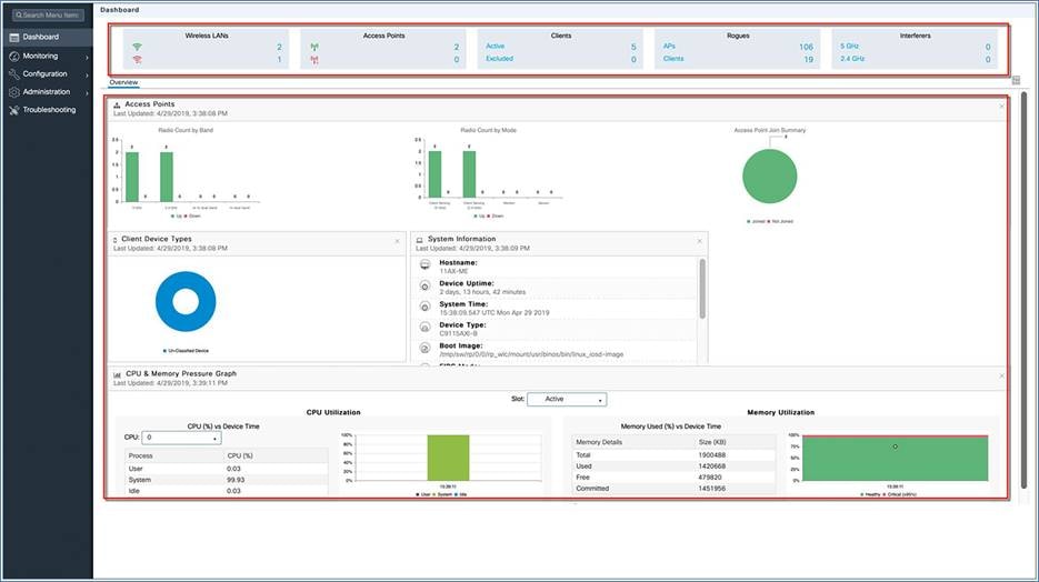
The network summary page appears on the main dashboard.
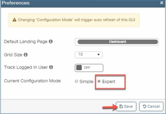
Note: For an advanced configuration or expert view, go to Preferences on the top right side of the page, set the Current Configuration Mode to Expert, and click Save.

Viewing the network summary
The monitoring service allows the admin to monitor the Cisco EWC network.
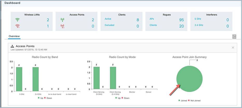
The monitoring dashboard
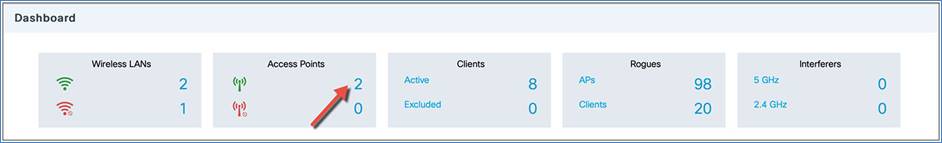
The monitoring dashboard of the network summary page displays counts of the following:
Wireless networks
Access points
Active clients in 2.4 GHz and 5 GHz
Rogue APs and clients
Interferers
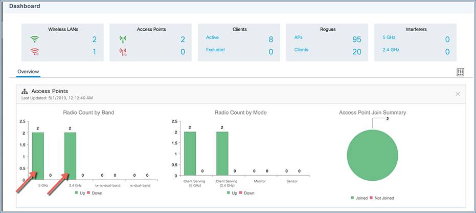
The network summary page has five customizable widgets representing data in both tabular and graphical formats for the following:
Access points (by band and mode)
Client device types
System information
CPU and memory pressure graph
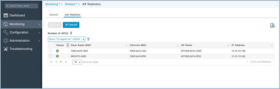
View an access points summary using the GUI
To view the access points using the GUI, perform the following steps:
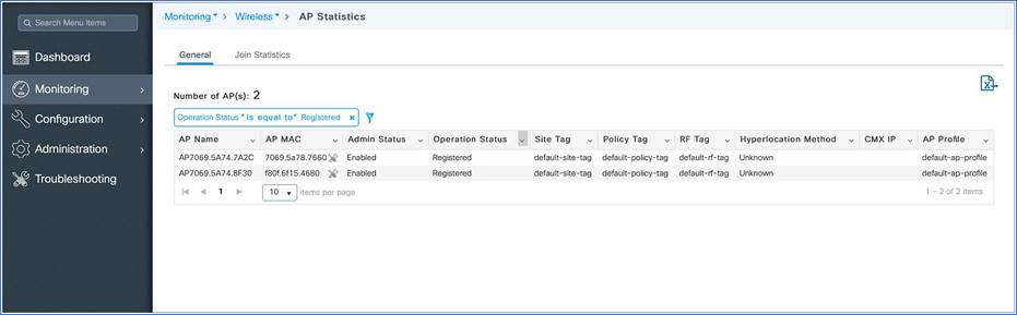
Step 1. Click the access points on the dashboard or go to Monitoring > Wireless > AP Statistics. A table displays the list of access points and gives the following information:
AP name
AP MAC address
Admin status
Operational status
Site tag
Policy tag
RF tag
CMX IP address
AP profile
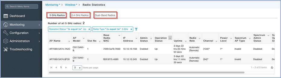
Step 2. Click the access points’ Radio Count by Band or go to Monitoring > Wireless > Radio Stats. A table displays the list of radios.
Step 3. Toggle between the 2.4 GHz, 5 GHz, and Dual-Band radio tabs to view a list of the access points operating at the respective radio frequencies.
Step 4. Click Access Point Join Summary or go to Monitoring > Wireless > AP Statistics > Join Statistics to view the AP join statistics.
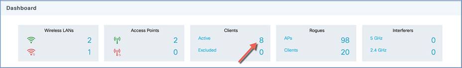
View client summary
To view a client summary using the GUI, perform the following steps:
Procedure
Step 1. Click Clients on the monitoring dashboard, or go to Monitoring > Wireless > Clients.
Step 2. (Optional) Click the down arrow on each column to filter the table view based on the desired parameters.

The Cisco Catalyst EWC configuration data model is based on design principles of reusability, simplified provisioning, enhanced flexibility, and modularization to help manage networks as they scale and to simplify the management of dynamically changing business and IT requirements.
This model provides a way for the client/AP devices to derive their configurations from profiles that are contained within tags. APs can be mapped to the tags either statically or as part of the rule engine that runs on the controller and takes effect during the AP join process. Configuration objects are modularized as objects, which helps in the reusability of the configuration. In addition, a flat tag-based configuration model eliminates the complexities associated with inheritance and container-based grouping, leading to a simpler and more flexible configuration that can ease change management.
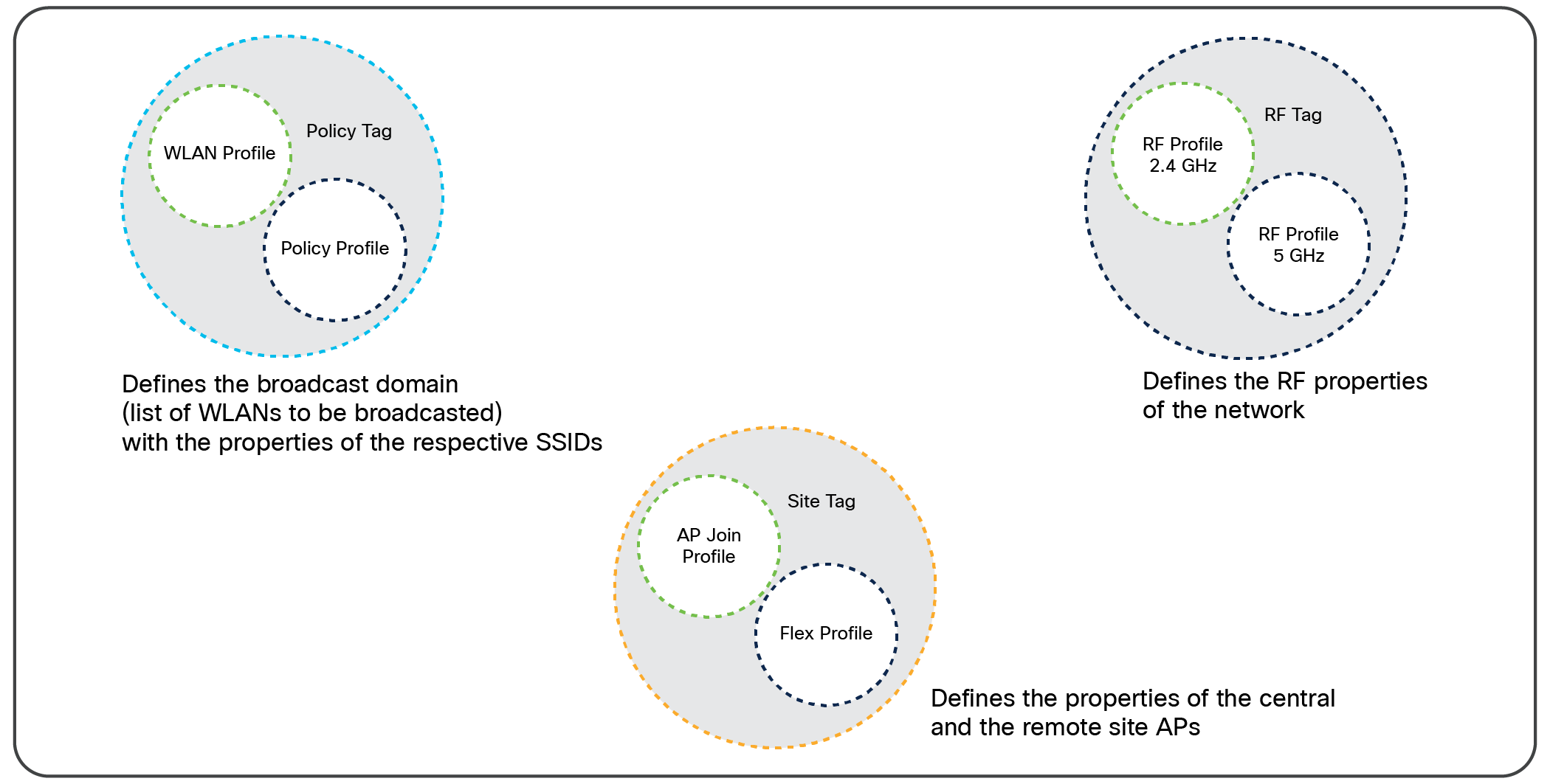
Elements of the configuration model – tags and profiles
Profiles
Profiles define the properties of the AP or associated clients. Profiles are reusable entities that can be used across tags. A default policy profile, AP join profile, flex profile, and 2.4-GHz and 5-GHz RF profiles are available by default on the wireless controller at boot time.
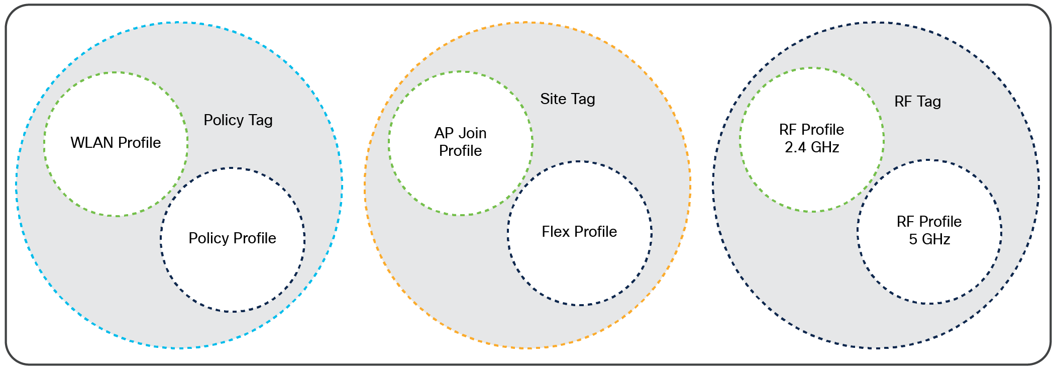
Profiles and tags
There are different kinds of profiles depending on the characteristics of the network they define.
WLAN profile
The WLAN profile defines the properties of a WLAN, such as profile name, status, WLAN ID, Layer 2 and Layer 3 security parameters, AAA server associated with this SSID, and other parameters that are specific to a particular WLAN.
Policy profile
The policy profile defines the network policies and the switching policies for a client, with the exception of QoS, which constitutes the AP policies as well. The policy profile is a reusable entity across tags. Anything that is a policy for the client applied on the AP/controller is moved to the policy profile. For example, VLAN, Access Control List (ACL), QoS, session timeout, idle timeout, Application Visibility and Control (AVC) profile, Bonjour profile, local profiling, device classification, etc. The switching policies define the central switching or local switching attribute of a WLAN.
The WLAN profile and policy profile are both part of a policy tag and define the characteristics and policy definitions of a set of WLANs.
AP join profile
The following parameters will be part of the AP join profile: Control and Provisioning of Wireless Access Points (CAPWAP) IPV4/IPV6, User Datagram Protocol (UDP) Lite, high availability, retransmit configuration parameters, global AP failover, hyperlocation configuration parameters, Telnet/SSH, 802.11u parameters, etc. For AP join profile changes, a small subset requires the CAPWAP connection to be reset, since these parameters pertain to the characteristic of the AP.
Flex profile
The flex profile contains the remote site-specific parameters. For example, the AP list, the Extensible Authentication Protocol (EAP) profiles, which can be used for the case in which an AP acts as an authentication server, local RADIUS server information, VLAN-to-ACL mapping, etc.
The AP join profile and flex profile are both part of a site tag and define the characteristics of a remote site.
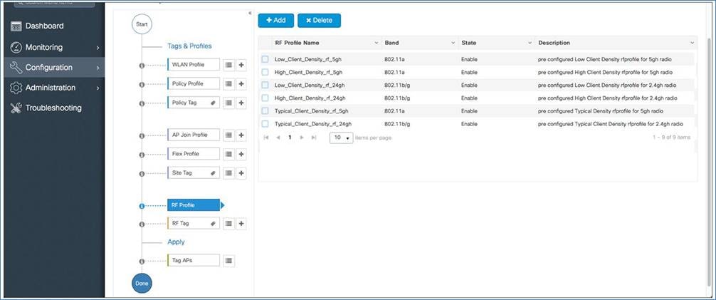
RF profile
There are two default RF profiles (one for 802.11a and one for 802.11b). RF profiles constitute the RF-specific configurations such as data rates, Modulation and Coding Scheme (MCS) settings, power assignment, dynamic channel assignment (DCA) parameters, coverage hold detection and mitigation (CHDM) variables, and High Density Experience (HDX) features. One 802.11a RF profile and one 802.11b RF profile can be added to an RF tag.
Tags
A tag’s property is defined by the policies associated with it. This property is in turn inherited by an associated client/AP. There are various types of tags, each associated with different profiles. No two types of tags include profiles with common properties. This helps eliminate precedence issues among the configuration entities to a large extent. Every tag has a default that is created when the system boots up.
The three kinds of tags
Policy tag
The policy tag contains the mapping of WLAN profiles to policy profiles.
A default policy tag with WLAN profiles and a WLAN ID < 16 is mapped to a default policy profile.
Site tag
The site tag consists of two profiles, the flex profile and the AP join profile. The site tag defines the properties of a site, for both central and remote (FlexConnect) sites. The attributes of a site that are common across central and remote sites are part of the AP join profile. The attributes that are specific to a remote site are part of the flex profile.
The default site tag consists of the default AP join profile. The default AP join profile values will be the same as those for the global AP parameters, plus a few parameters from the AP group in the current configuration, such as preferred mode, 802.11u parameters, location, etc.
Note: In EWC only one site tag is supported and it has to be the default-site-tag. Also, in EWC there is no central site concept as EWC is a FlexConnect local switching deployment.
RF tag
The RF tag contains the 2.4-GHz and 5-GHz RF profiles.
The default RF tag consists of the default 2.4-GHz RF profile and the default 5-GHz RF profile. These default profiles contain default values for the global RF profiles for the respective radios.
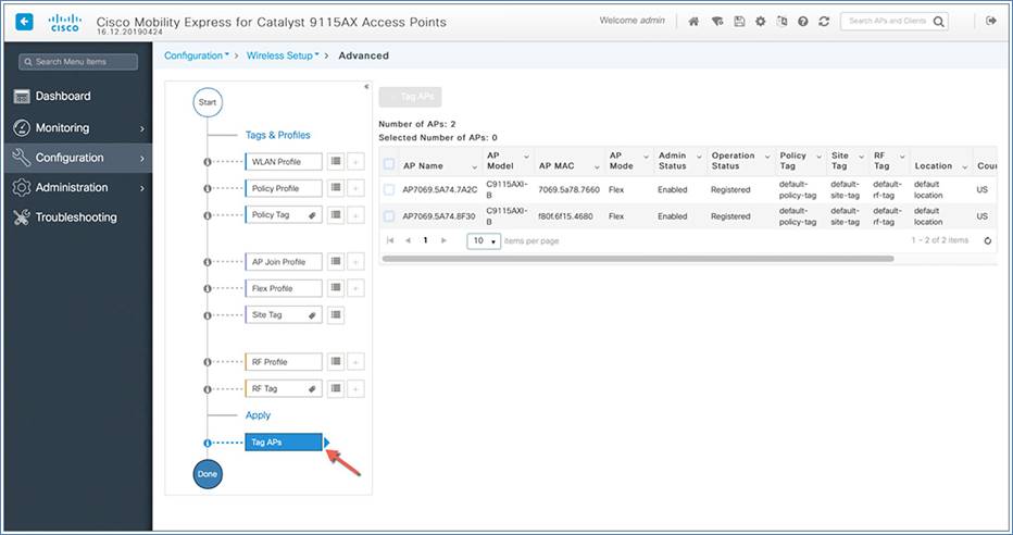
Association of tags to APs
Access points are tagged based on their broadcast domain, the site the AP belongs to, and the RF characteristics desired. Once tagged, an AP gets a list of WLANs to be broadcasted, along with the properties of the respective SSIDs, properties of the APs on the local or remote site, and RF properties of the network. By default, an AP is tagged with the default policy, site, and RF tag unless explicitly changed. When a tag associated with an AP is changed, the AP resets its CAPWAP connection.
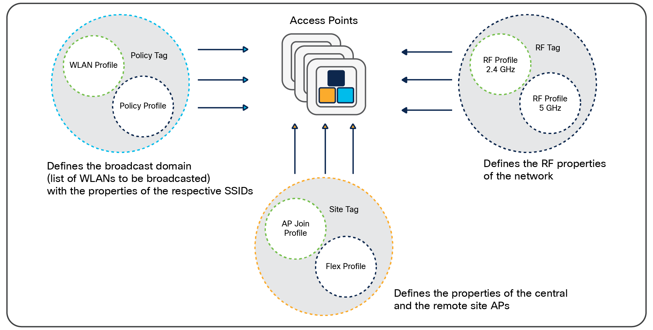
How access points are tagged
Creating a WLAN through basic wireless setup
The basic wireless setup uses intent-based workflows to define a site, create wireless networks for that site, define policies such as VLAN, ACL, and QoS, and also fine-tune RF characteristics. Corresponding policies and tags are created in the back end in accordance with the new configuration model, but they are transparent to the end user. Access points are assigned to the site and in turn are assigned policy, RF, and site tags.
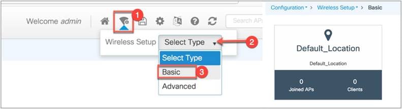
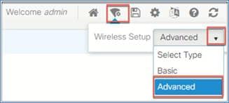
To access the basic wireless setup, click the Wireless Setup icon in the top right corner of the dashboard page.
Step 1: From the EWC top right corner, go to Wireless Setup > Select Type > Basic, then click Default_Location.
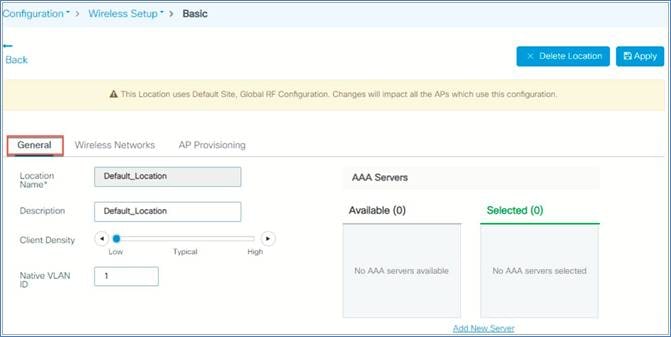
Step 2: From the General tab, you can define parameters such as client density, native VLAN, and AAA server as per their deployments.
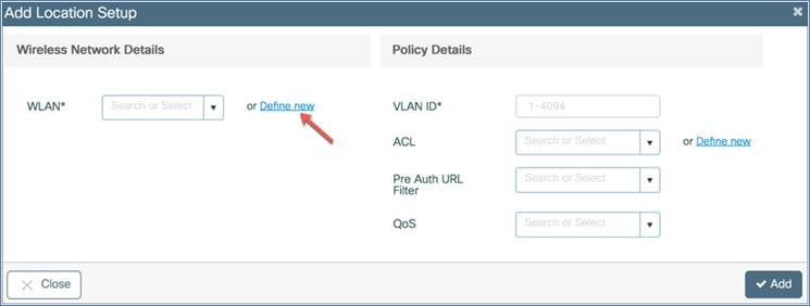
Step 3: WLANs created as part of a day-0 setup are available to add to this site. These WLANs can be added as is or modified for the policy details that are required for this network in the site. Alternatively, new SSIDs can be created using the “Define new” button.
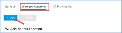
To add a new WLAN go to the Wireless Networks tab and click +Add, then click Define new to configure the WLAN.
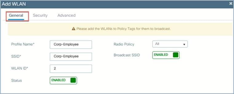
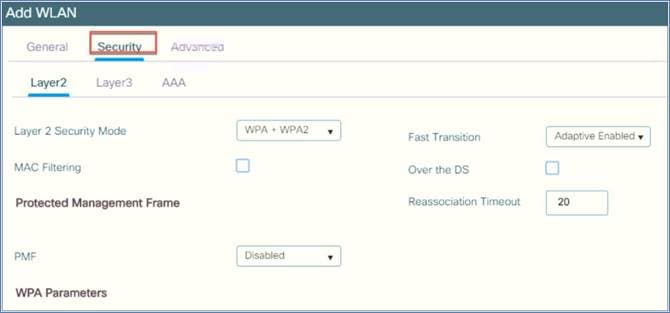
Step 4: This opens a WLAN window. On the General tab, configure the WLAN profile name, SSID, WLAN ID, and radio policy. Enable the status, and then go to the Security tab.
Step 5: You can define the security settings per the required configuration.
Step 6: Now you need to provision the AP. Select the AP from the available AP list and click the arrow. The AP will be moved to the list of APs associated with the location. Then click Apply.
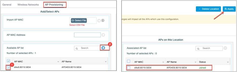
Policy, site, and RF tags are automatically pushed to the access points upon provisioning.
Creating a WLAN through advanced wireless setup
Access the wireless setup by clicking the Wireless Setup icon in the top right corner of the dashboard page.
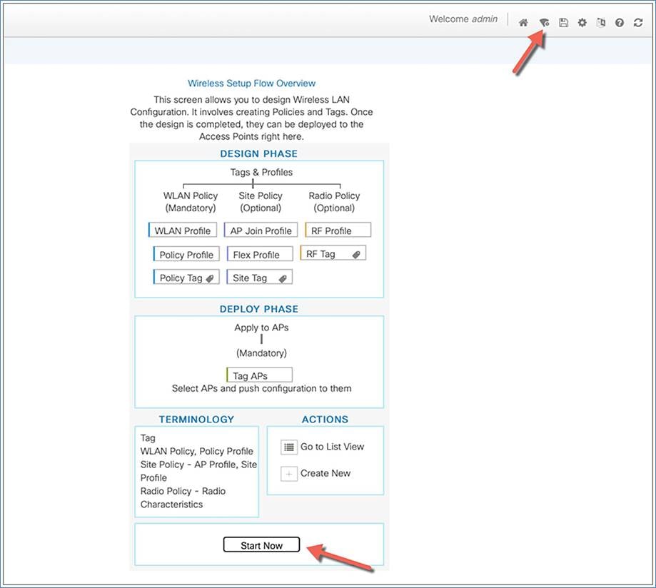
A guided workflow has been created for easy navigation through the steps required to set up the network on the Cisco Catalyst wireless controllers.
Procedure
Choose Wireless Setup > Advanced, then, after reviewing the notes on this page, click Start Now to begin setting up the wireless network.
Note: The following set of steps defines the logical order of configuration. Apart from the WLAN profile, all profiles and tags have a default object associated with them.
1. Create profiles
● Create the required WLAN profiles (SSIDs)
● Create the policy profiles (if non-default needed)
● Create the RF profiles (if non-default needed)
● Create the site profile (if non-default needed)
2. Create tags
● Create the policy tag (if non-default needed) and map the SSIDs above to the policy profiles as required.
● Create the RF tag (if non-default needed) and add the RF profiles for 802.11a and 802.11b to it.
● Create the site tag (if non-default needed) and add the flex profile (if the site is a remote site) and the AP join profile (most cases will use the default)
3. Associate the tags to APs
If no custom tags are needed, this step is not required, as default tags are associated with the APs.
If the tag to be associated is non-default, associate it to the APs.
● Associate the RF tag to the AP or set of APs.
● Associate the policy tag to the AP or set of APs.
● Associate the site tag to the AP or set of APs.
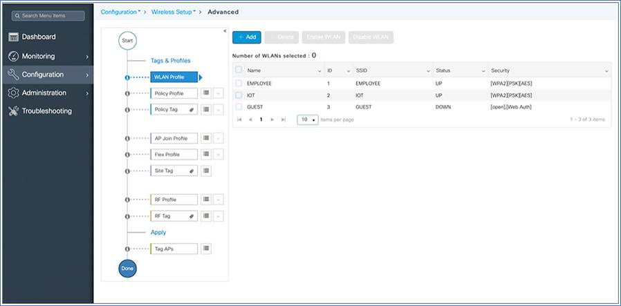
Creating a WLAN profile
Begin the WLAN configuration by clicking the + sign next to the WLAN profile.
Click the Add button.
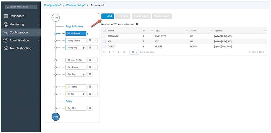
Note: SSIDs created during the day-0 flow will automatically show up on the WLAN profiles page.
Specify the profile name of your choice and a WLAN ID between 1 and 16, and set the Status toggle button to Enabled.
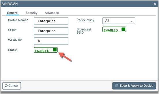
Adaptive 802.11r and other best practices are turned on by default.
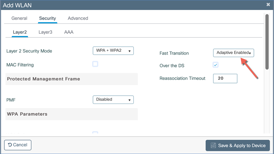
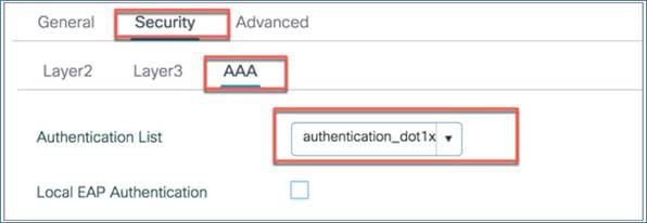
Select PSK or 802.1X as the Authentication Key Management (AKM) on the Security tab. Click Save and Apply to Device.
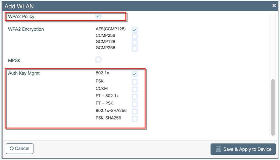
If 802.1X is selected, make sure you have added the AAA/RADIUS server. This can be done on day 0 through the configuration setup wizard or as part of day-1 configuration. If you configured the RADIUS server settings on day 0, it will automatically create a RADIUS server (RADIUS_SERVER_DAY0_1), RADIUS server group (RADIUS_SERVER_GROUP_DAY0), and AAA method list name (authentication_dot1x_day0). This method list will appear in WLAN > Security > AAA > Authentication List.
For day-1 RADIUS configuration, please refer to the “Configuring the AAA/RADIUS Server” section of this guide.
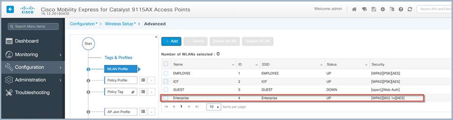
Verify that a WLAN profile is created as follows.
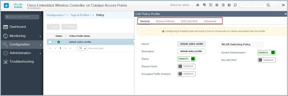
Policy profile
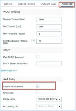
The default policy profile and default policy tag are preconfigured, so no specific policy configuration is required unless they need to be customized (for example, access policies, local switched VLAN, QoS, AVC, AAA override, etc)
You can configure the local switch VLAN under the option Access Policies > VLAN > VLAN/VLAN Group.
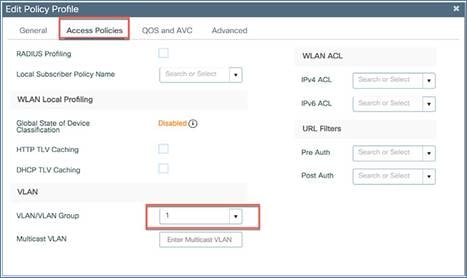
You can also apply or pass some AAA attributes to the WLAN tied to a specific policy profile by selecting the Allow AAA Override option under Advanced > AAA Policy.
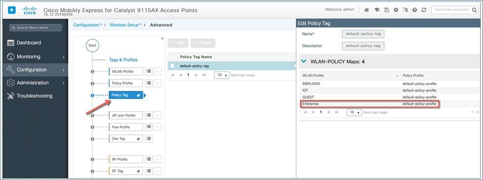
Policy tag
By default, WLAN IDs 1 through 16 are associated with the default policy tag. The SSID created in the first step is automatically added to this default policy tag, as shown below.
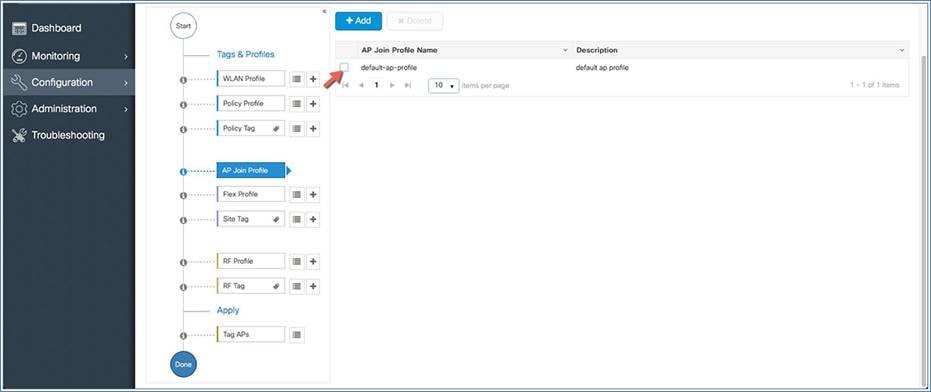
A default AP join profile and site tag are available automatically, so no specific site configuration is required. The EWC supports only one global site, which is the default site tag.
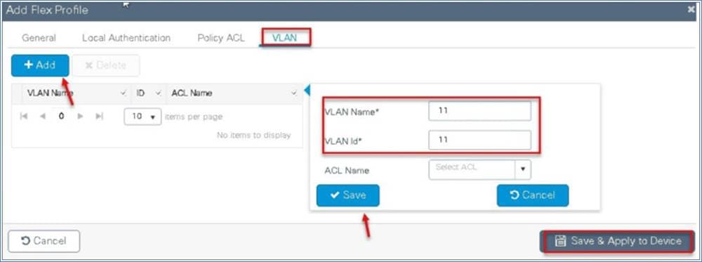
Flex profile
The flex profile is used for configuring the VLANs on the AP when the VLAN is overridden by the AAA that is used for the local switched SSIDs.
You can define the native VLAN for the flex profile.
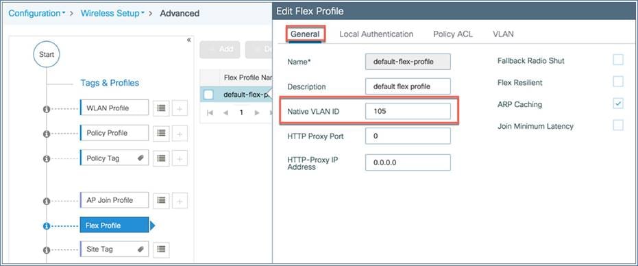
You can also define the VLANs to be used for the local switched SSID. In this example we use VLAN 11, which is the local switched VLAN from the AP when using the AAA VLAN override option.
RF profile
A default RF profile and RF tag are preconfigured, so no RF configuration is required.
APs are tagged with the default policy, site, and RF tags automatically, so no explicit tagging is needed and the SSIDs (1 through 16) will start broadcasting across the network.
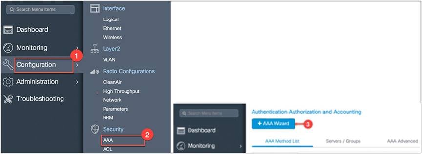
Configuring the AAA/RADIUS server
If the AAA server settings are not configured on day 0, you can add an AAA/RADIUS server using the following steps.
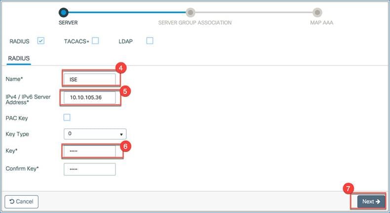
From the EWC main menu, go to Configuration > Security > AAA and then click +AAA Wizard.
Configure the following:
1. RADIUS: Name, server IP address, and key (shared secret). Click Next. In this example we name it “ISE.”
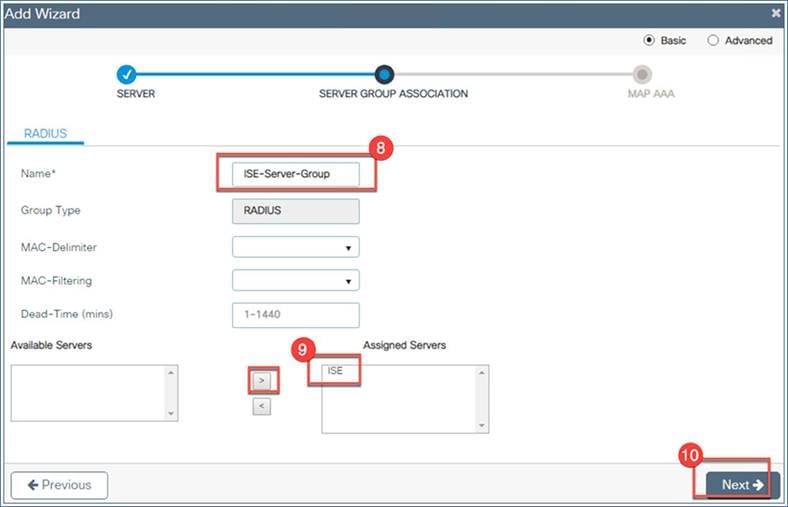
2. Server group association: Configure the name of the server group, then from the Available Servers list, select the server you just created (“ISE” in this example). Click the > symbol to move it to the Assigned Servers list, and click Next.
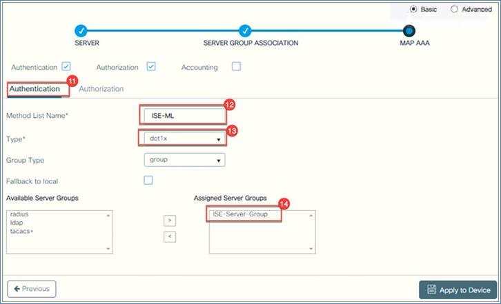
3. MAP AAA: Select Authentication, then configure the Method List Name(if you do not want to use the default) and set the Type to dot1x, Under Available Server Groups, select the group you created. In this example we created ISE-Server-Group. If you are not using authorization, uncheck the Authorization box. Click Apply to Device.
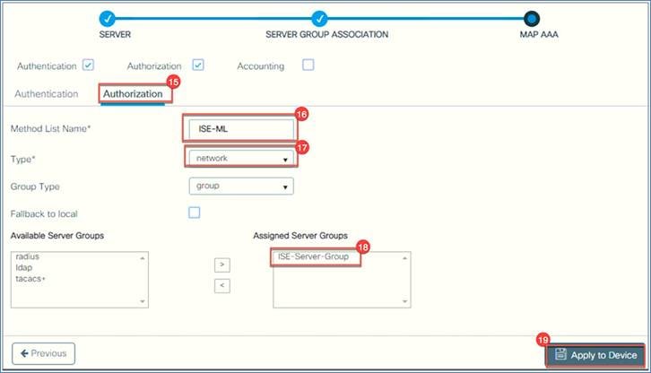
4. If you want to configure authorization, go to Authorization and select Type = network. Under Available Server Groups, select ISE-Server-Group, then click Apply to Device.
Configuring management access using the GUI
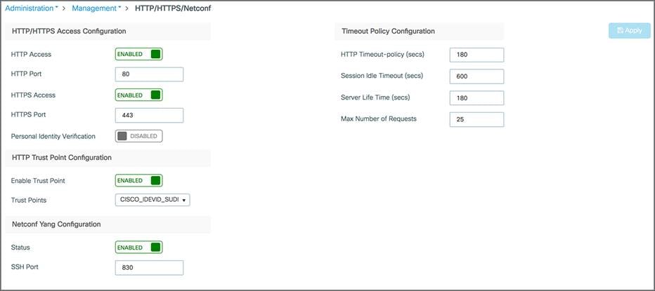
The management access interface on the EWC controller is the default interface for in-band management of the controller and connectivity to enterprise services. It is also used for communications between the controller and access points. Go to Administration > Management > HTTP/HTTPS/Netconf.
HTTP access: To enable HTTP access mode, choose Enabled from the HTTP Access drop-down list. This allows you to access the controller GUI using http://<ip-address> through a web browser. Otherwise, choose Disabled.
The default value is Disabled. HTTP access mode is not a secure connection.
HTTPS access: To enable HTTPS access mode, choose Enabled from the HTTPS Access drop-down list. This allows you to access the controller GUI using http://<ip-address> through a web browser. Otherwise, choose Disabled.
The default value is Enabled. HTTPS access mode is a secure connection.
Similarly, The HTTP trust point is enabled by default. Also, Netconf is enabled by default with default port number 830.
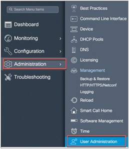
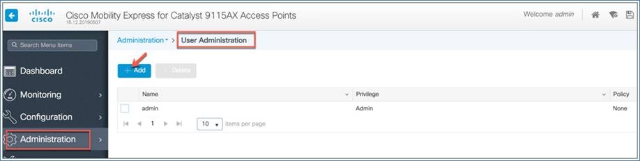
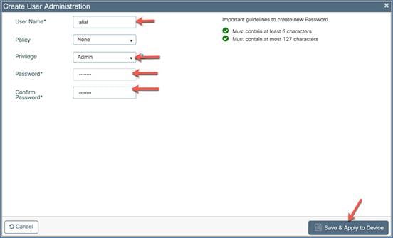
Managing administrator accounts
You can configure administrator usernames and passwords to prevent unauthorized users from reconfiguring the controller and viewing configuration information.
The administrator user accounts are required for logging into the EWC controller to monitor and configure the wireless network. They can be configured with read/write or read-only privileges by going to the WLC main menu and then choosing Administration > User Administration > Add.
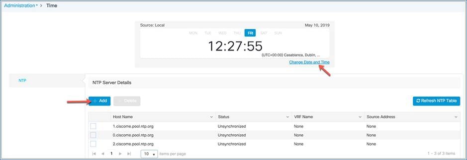
Managing time on the EWC
The system date and time on the Cisco EWC are first configured when you run the initial wireless express setup wizard. You can change or configure the time from the WLC menu by choosing Administration > Time.
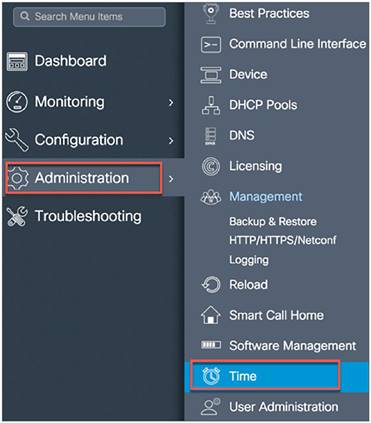
A Network Time Protocol (NTP) server can be configured to synchronize date and time if one was not configured during the wireless express setup. Greenwich Mean Time (GMT) is used as the standard for setting the time zone on the controller. You can also update or add the specific NTP server to EWC.
Updating Cisco EWC software
Cisco Catalyst EWC software updates can be performed using the controller’s web interface. Software updates help ensure that both the controller software and all the associated APs are updated. The APs that have older software are automatically upgraded to the EWC software upon joining the primary AP. An AP joining the controller compares its software version with the primary AP version and, in case of a mismatch, the new AP requests a software upgrade. The primary AP facilitates the transfer of the new software from the TFTP server to the new AP.
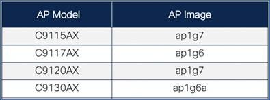
Both the Cisco Catalyst 9115AX and 9120AX Series access points share the same AP image file – ap1g7 – while the 9117AX Series image is ap1g6 and C9130 Series AP image is ap1g6a, which is included as part of the C9800-AP-universalk9.<version>.zip file. For HTTP transfer mode, specify the path to the access point image file on your local machine.
The active AP facilitates the transfer of the image from the TFTP server to the subordinate APs. The AP images are stored and served from the TFTP server upon request.
Before you upgrade the EWC network, ensure that the following prerequisites are met:
Prerequisites for HTTP software update
● The network should be homogeneous, meaning that all APs have a same ap image type. Otherwise, TFTP/SFTP download is required.
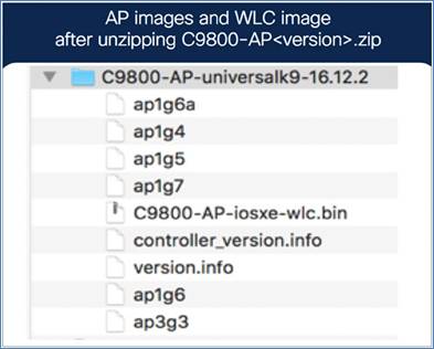
● The AP bundle with individual AP images (ap1g6, ap1g6a, ap1g7, ap3g3, etc.) and WLC image (C9800-AP-iosxe-wlc.bin) downloaded from Cisco.com is unzipped and copied onto the local machine.
● The unzipped EWC image folder and mapping of AP models to AP image are shown below for your reference.
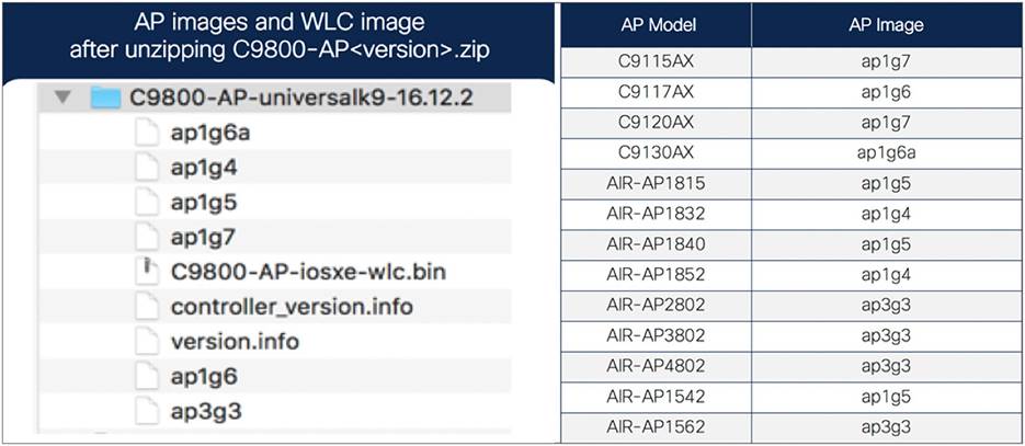
Mapping of AP images to AP models
Prerequisites for TFTP software update
● A TFTP server is reachable from the management IP address of the EWC.
● The upgrade bundle with AP images (ap1g6, ap1g6a, ap1g7, ap3g3, etc.) and WLC image (C9800-AP-iosxe-wlc.bin) downloaded from Cisco.com is unzipped and copied onto the TFTP server. The unzipped EWC image folder and mapping of AP models to AP image are shown below for your reference.
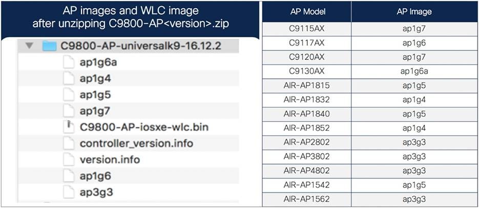
Mapping of AP images to AP models
Software update sequence
Download the C9800-AP-universalk9<version>.zip file from Cisco.com. For HTTP transfer mode, download the file to the local machine that is being used to access the EWC web UI. For TFTP transfer mode, download the zip file to the device running the TFTP server.
● Unzip the file to extract the AP images.
● Select HTTP, TFTP, or SFTP as the transfer mode, and configure the corresponding parameters on the software upgrade page.
● Initiate image predownload on the EWC network.
● Activate and reboot the EWC and associated access points.
To begin the software update, perform the following steps:
HTTP download procedure
Step 1. Download the C9800-AP-universalk9<version>.zip file from the beta site to the local machine (unzipped file).
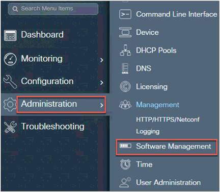
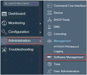
Step 2. From the WLC main menu, go to Administration > Software Management > Software Upgrade.
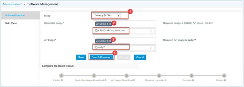
Step 3. From the Mode drop-down menu, select Desktop (HTTP).
For the Controller Image option, click Select File, which will open your local machine drive. Choose the C9800-AP-iosxe-wlc.bin file.
For the AP Image option, click Select File, which will open your local machine drive, and then select the AP image file.
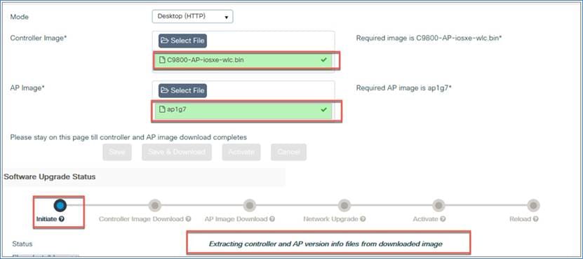
Click Save and Download. Remain on the page until the green progress bar for the controller and AP image shows that it is complete.
Step 4. Check the software upgrade status, which will show update messages regarding the AP and controller images. The options (Save, Save and Download, and Activate) will be grayed out.
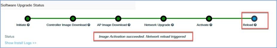
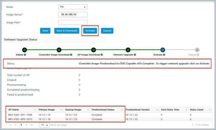
Step 5. Once the software upgrade status shows the message “Controller Image Predownload to EWC Capable APs Complete,” click the Activate button to initiate the software.
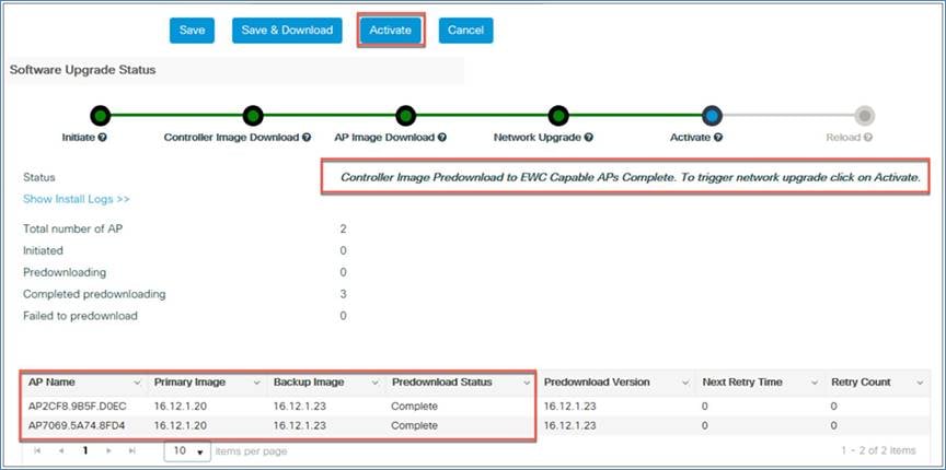
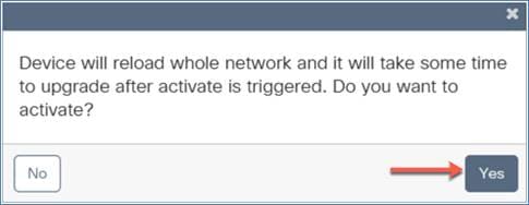
A warning window will pop up, letting you know that this will cause the device to reboot.
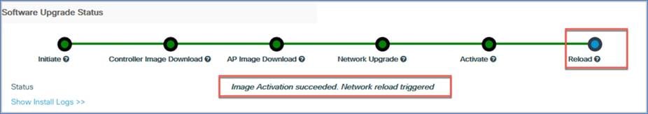
Click Yes and the EWC will reload and will come back up with the updated software.
TFTP download procedure
Step 1. Download the C9800-AP-universalk9.<version>.zip file from the beta site to the TFTP server (unzipped file).
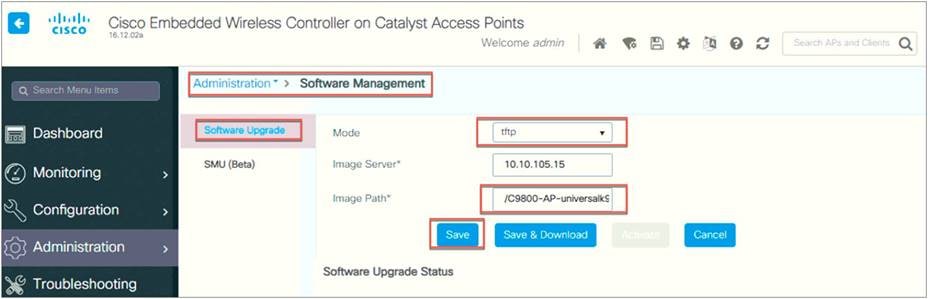
Step 2. From the WLC main menu, go to Administration > Software Management > Software Upgrade.
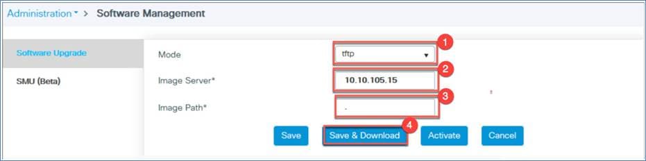
Step 3. From the Mode drop-down menu, select TFTP.
Select the image server IP address (TFTP server IP address)
Define the path. Use a period (.) if a TFTP directory is already set up on the TFTP server.
Click Save and Download to start the software upgrade.

Step 4. Once the software upgrade status shows the message “Controller Image Predownload to EWC Capable APs Complete,” click the Activate button to initiate the software.

AP image download profile for heterogeneous network
If the AP being added to the EWC network is the same model and image as the active EWC, you do not need any external server to host the code. If the AP model and image are different from the active AP, you need to have an external server to host the code so the APs can download the code at the time of joining.
For example, in an EWC network, if the active EWC is a 9120AX and the subordinate APs are 9115AX, 9117AX, and 9130AX models, you need to set up an external server to host the code so that the 9117AX and 9130AX APs can download the code for the server.
From the WLC main menu, go to Administration > Software Management > Software Upgrade. Select TFTP or SFTP for the transfer mode, configure the SFTP or TFTP parameters, and save the profile by clicking Save.
Logging
The System Message logging feature logs system events to a remote server called a syslog server. Each system event triggers a syslog message that contains the details of the event.
If the System Message logging feature is enabled, the controller sends a syslog message to the syslog server that is configured on the controller.
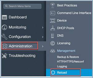
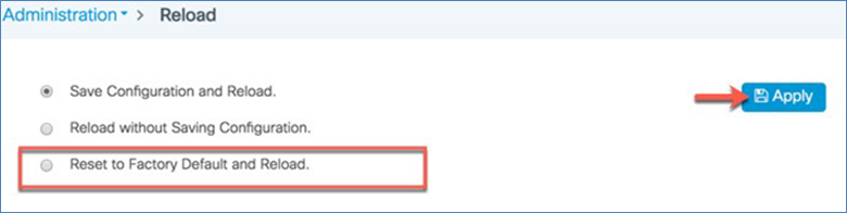
Reset to factory default
You can return the EWC network to its default configuration by resetting it to the factory default.
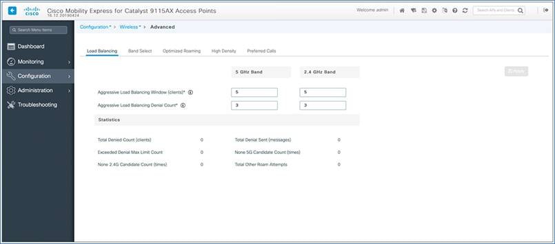
Wireless advanced settings
You can also configure advanced parameters such as load balancing, band select, and optimized roaming from the WLC main menu by navigating to Configuration > Wireless > Advanced.
The Cisco Catalyst EWC is supported on Cisco Catalyst 9100 Access Points, and the active AP election process determines which 9100 AP will be elected to run the EWC function. Once the active AP is elected and other subordinate EWC-capable 9100 APs are joined to it, it selects a standby AP and redundancy is formed.
This High Availability (HA) architecture is based on the Cisco Catalyst 9800 HA architecture, with a few additions:
HA pairing will be different. For the initial bring-up, the EWC active will wait until all APs join. It then selects the designated standby (via either auto-selection or configuration) and communicates that role and the HA parameters (local/peer IP, keepalive interval, priority, etc.) to the selected AP via a CAPWAP control message.
The selected standby AP starts up and dynamically configures the HA parameters without manual intervention.
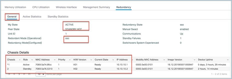
To view the redundancy between active and standby, access the EWC GUI.
Go to Monitoring > System > Redundancy.
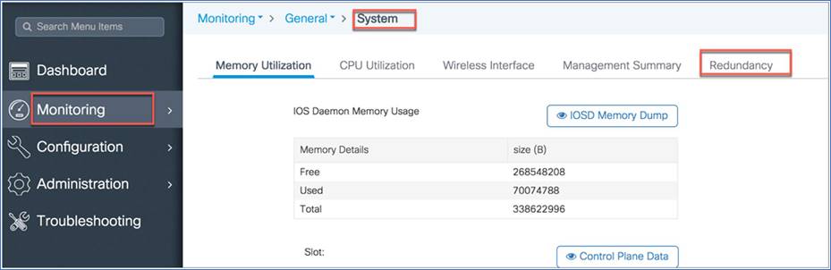
From the General tab, you can view the active and standby mode and details.
The EWC election process is used to choose the AP on which the controller is started. We use Virtual Router Redundancy Protocol (VRRP) to elect the active AP. The logic used to elect the active and standby EWC is described below.
Active EWC selection
The following algorithm is used to compare two APs.
● If you have configured an AP to be a preferred controller, it takes the highest precedence.
● The next AP type is compared. APs with higher model numbers will have higher values. The AP having the highest value will become the active.
● If the APs have the same AP type, the client load (number of associated clients) is compared and the AP with the smallest load is selected.
● If all of the above fails (all are equal among the APs), the AP with the lowest MAC address becomes the active.
Standby EWC selection (on day 1 only)
The standby EWC is not selected using VRRP. It is selected as follows.
● After the active EWC is selected, it will wait until the external APs join to begin standby election.
● Once the external APs join, the active will assign a priority to all joined APs. The AP with the highest priority will be selected as the standby. If multiple APs have the same highest priority, the AP with the lowest MAC address gets selected. Only EWC-capable APs with an EWC image installed can participate in the election.
● Priority is calculated based on the following parameters:
◦ Explicit user configuration: Choose a particular AP as the next preferred controller (highest priority)
◦ AP type
◦ AP join time
Day 0 vs. day 1
There is no concept of standby on day 0. On day 0, you will have only one active EWC. If the active EWC goes down for some reason, VRRP election will take place again, to elect a new EWC.
Note: Once a controller is running on an AP, it will always have a higher priority than other APs not running as the controller. For example, if you bring up one 9115AX Series AP, since there is no other AP to choose from, it will become the active and start controller. If you then bring up a 9117AX Series AP on this network, although the 9117AX is a higher model number, it will not become the controller, since you already have a controller running in the network. Election will kick in only if you bring up two APs at the same time.
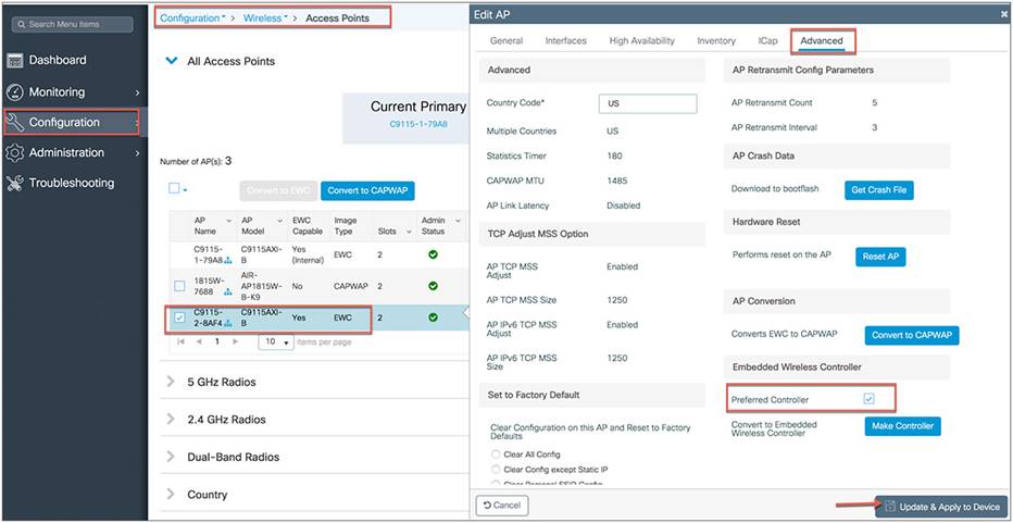
Preferred controller selection (new standby EWC)
The active and standby EWCs are elected by the process described above. But if for some reason you want to select another AP as the standby, you can select any EWC-capable AP as a preferred controller.
Note: When you select another AP that is not the current standby to be the preferred controller, the current standby goes down and the new EWC you have selected becomes the standby EWC.
Step 1: Select the EWC AP that you want to be a preferred controller.
Step 2: Go to the AP’s Advanced tab and, under Embedded Wireless Controller, select Preferred Controller and click Update and Apply to Device.
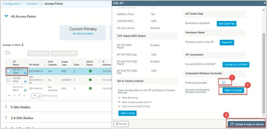
Make Controller option (selecting a new active EWC)
The active EWC and standby EWC are elected by the process described above. But if for some reason you want to select another AP to be the active EWC, you can do so with the Make Controller option. You need to configure it as a preferred controller first before using this option. When you select an AP that is not the current active EWC to become the controller, the new AP becomes the active EWC after a reload, and the current EWC will become the new standby.
Step 1: Select the EWC AP that you want to be a preferred controller.
Step 2: Go to the AP’s Advanced tab and, under the Embedded Wireless Controller option, select Preferred Controller and click Update and Apply to Device.
Step 3: Go back to the EWC AP Advanced tab and click Make Controller, then click Update and Apply to Device.
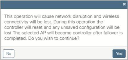
Note: There will be a warning message that this operation will disrupt the network, as the controller will reset.
Note: Conversion from CAPWAP to EWC is supported from AireOS 8.10.105.0 or Cisco IOS XE 16.12.2s. The AP must have the 8.10.105.0 or 16.12.2 CAPWAP image or later on the 9100 access point before you can convert it to EWC.
The Cisco Catalyst 9100 Access Point is capable of operating as a CAPWAP AP or EWC-capable AP (runs the controller function in an EWC network), managing other access points as well as serving clients.
The following conversion is supported:
Converting a CAPWAP AP to an EWC-capable AP: This conversion is required when you have a 9100 access point running an 8.10.X or 16.12.X CAPWAP image, and you want to use it to deploy a EWC network. For this, you would convert the CAPWAP AP to a active EWC AP (runs the controller function in an EWC network).
The Cisco Catalyst 9100 Access Points support two different images:
CAPWAP image: When a CAPWAP image is installed on an access point, it can operate only as a CAPWAP access point and does not support the controller function.
EWC image: When an EWC image is installed on an access point, it can operate as both a controller and an access point or as an access point alone.
To determine the image and capability on the access point, you can do a show version command on the AP CLI to determine the AP image type and AP configuration:
If the show version command does not display the AP image type and AP configuration parameters, it means the AP is running the CAPWAP image.
If the show version command displays the AP image type as EWC IMAGE and the AP configuration as EWC CAPABLE, it operates as both a controller and an access point. It participates in the active election process in case of a failover.
If the show version command shows the AP image type as EWC IMAGE and the AP configuration as NOT EWC CAPABLE, it operates only as an access point and does not participate in the active election process in case of a failover.
The following is sample input from the show version command:
Cisco C9117AXI-B with 1927052/380724K bytes of memory.
Processor board ID KWC224709BU
AP Running Image : 16.12.2
Primary Boot Image : 16.12.2
Backup Boot Image : 8.10.105.5
Primary Boot Image Hash:
Backup Boot Image Hash:
AP Image type : EWC IMAGE
AP Configuration : EWC CAPABLE
1 Gigabit Ethernet interfaces
2 802.11 Radios
Radio FW version : QC_IMAGE_VERSION_STRING=WLAN.HK.1.0-03095-QCAHKSWPL_SILICONZ-1.198262.4.200256.9
NSS FW version : NSS.HK.H.CS.q_len512-E_custC
cisco C9117AXI-B with 1927052/1296108K bytes of memory of memory.
Processor board ID RFDP2BCR021
AP Running Image : 16.12.2
Primary Boot Image : 16.12.2
Backup Boot Image : 8.10.105.5
AP Image type : EWC IMAGE
AP Configuration : NOT EWC CAPABLE
2 Gigabit Ethernet interfaces
2 802.11 Radios
Radio FW version : 1401b63d121b073a3008aa67f0c039d0
NSS FW version : NSS.AK.1.0.c4-00O26-E_cust C-1. 24160.1
Converting a CAPWAP AP to an EWC AP
To convert an access point running a CAPWAP image into an EWC-capable access point, you have to download and install the EWC image from a TFTP server. A single command has been provided to download the EWC image from a TFTP server and convert the AP configuration to EWC CAPABLE.
Prerequisites for converting a CAPWAP AP to EWC
● A TFTP server with the EWC image file unzipped. The unzipped file has the EWC image C9800-AP-iosxe-wlc.bin and respective AP images (ap1g6, ap1g6a, and ap1g7).
● A DHCP server to assign an IP address to the Cisco Catalyst 9100 Access Point.
● The 9100 access point must not join any existing controller in the network when you are trying to load the EWC image. If you have an existing controller on your network that the AP can join, conversion will not be successful.
To convert an AP running a CAPWAP image to EWC, perform the following steps:
Procedure
Step 1. Connect and log in to the Cisco Catalyst 9100 Access Point CLI or console.
Step 2. Enter enable to go to privileged execution mode.
Step 3. Enter show version on the access point CLI. From the show version output, you can determine the AP image type and AP configuration and can then proceed with the conversion process.
Step 4. If the AP image type and AP configuration are not available in the show version output, it means the AP is running a CAPWAP image. To do the conversion, execute the command below:
AP#ap-type EWC tftp://<TFTP Server IP>/< ap image> tftp://<TFTP Server IP>/< WLC image>
Example: AP#ap-type EWC tftp://10.10.10.15/ap1g7 tftp://10.10.10.15/C9800-AP-iosxe-wlc.bin
Step 5. After the AP reboots, the EWC starts in day 0 and CiscoAirProvision-<MAC> SSID is broadcast. You can then configure it from the wireless configuration wizard.
Converting an EWC AP to a CAPWAP AP from the web UI
There are two reasons to convert an EWC-capable AP to a CAPWAP AP:
● If you want to migrate the 9100 access points from an EWC network to another controller (not EWC) network.
● If you do not want the 9100 access points to participate in the active AP election process in an EWC network.
When the AP type is CAPWAP, the AP doesn't have the controller function and cannot participate in the active AP election process.
After changing the AP type, if this AP is migrated to a non-EWC network, it joins the controller in that network. If the image on that controller is different from the one on the AP, a new CAPWAP image is requested from the controller.
When the AP type is CAPWAP (as required for this conversion), the AP doesn’t start its own controller function, and when the AP joins the external controller, a new image is requested from the controller and the AP gets the CAPWAP image.
To convert an EWC AP into a CAPWAP AP, perform the following steps:
Procedure
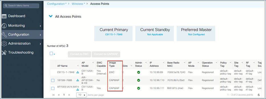
Step 1: Go to Configuration > Wireless > Access Points and view the APs. The image type shows whether the AP is CAPWAP or EWC.
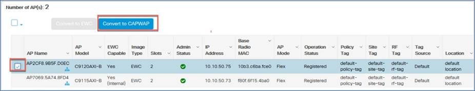
Step 2: You can select an individual AP or multiple APs to convert to CAPWAP.
Converting EWCs to CAPWAP using option 43
DHCP option 43 is a vendor-specific option and is used for providing WLC IP addresses to the access point. Using option 43 with a specific subtype option, you can have the EWC convert to CAPWAP and join a WLC appliance or virtual controller. After the AP receives DHCP option 43 and subtype 0xF2 at bootup, the AP type will be converted to CAPWAP, and the AP will follow the regular joining process.
The DHCP configuration on the switch is shown below.
Switch(dhcp-config)#option 43 hex F2056464645801
EWC to CAPWAP AP conversion using the AP CLI
You can convert an EWC to function as CAPWAP by executing a single command from the access point CLI:
AP#ap-type capwap
Note: The access point will reboot and the AP type will change to NOT EWC CAPABLE. Also, after the AP is converted to CAPWAP, it will no longer participate in the active election process.
Migrating an EWC network to a controller-based network
If you need to have more than 100 APs on the network, you can easily migrate your existing EWC network to a controller-based network, which can be Cisco Catalyst 9800 Series (appliance or virtual) or AireOS (3504, 5520, or 8540 wireless controller or virtual controller running 8.10.X software)
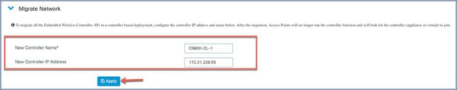
Step 1: From the EWC web UI, navigate to Configuration > Wireless > Access Points, then scroll down to the Migrate Network option.
Step 2: Configure the name and IP address of the controller to which you want to migrate the APs, then click Apply. After the migration, the APs will not run the controller function and will join the configured controller.
Site Survey Option
Cisco EWC on Catalyst APs is next-generation autonomous and supports Site Survey in Cisco IOS XE Release 16.12.2s. The following access points with the EWC image support the Site Survey capability:
Cisco Catalyst 9120AX Series (C9120AX-x)
Cisco Catalyst 9117AX Series (C9117AX-x)
Cisco Catalyst 9115AX Series (C9115AX-x)
Cisco Catalyst 9130AX Series (C91130AX-x)
Cisco EWC supports an internal DHCP server and operates without a pingable gateway. This enables the user to take the access point powered by a battery pack and a client device to perform an active survey. User need to have a power adapter connected to external power supply.
To run the EWC as site survey AP user need to start with day-0 configuration as described in the section day-0 provisioning of this document.
Once the provisioning is complete and the configured SSID comes up, join it using your defined PSK, and open your web browser to https://192.168.1.1 or https://mywifi.cisco.com.
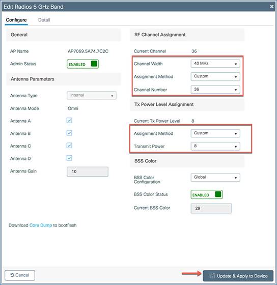
To set the transmit power and channel of the radio, navigate to Configuration > Access Points > 5 GHz radio or 2.4 GHz radio > select the AP. From here you can change the channel and transmit power of your APs radio by changing the Assignment Method from Global to Custom, setting the required values, then clicking ‘Update and Apply to Device’.
● Quick Start Guide:
https://www.cisco.com/c/dam/en/us/solutions/collateral/enterprise-networks/mobility-express/guide-c07-741338.pdf
● Deploying EWC-AP demo:
https://xd.adobe.com/view/76b25e06-d905-487c-4de1-3d19719a5ac5-0083/
● CAPWAP AP Conversion to EWC-AP demo:
https://xd.adobe.com/view/8fd6c90c-2543-4ded-772c-12be163103f7-f9e7/
● Guest access with Cisco Spaces demo:
https://xd.adobe.com/view/e7af8c14-b2ea-426c-5bf4-0ca6efa022f5-919e/
● Release Notes:
https://www.cisco.com/c/en/us/td/docs/wireless/controller/ewc/16-12/rel-notes/ewc-rn-16-12-2.html
● Config Guide:
https://www.cisco.com/c/en/us/td/docs/wireless/controller/ewc/16-12/config-guide/ewc_cg_16_12.html
● Command Reference:
https://www.cisco.com/c/en/us/td/docs/wireless/controller/ewc/16-12/cmd-ref/ewc_cr_16_12.html
● Online Help:
https://www.cisco.com/c/dam/en/us/td/docs/wireless/controller/ewc/16-12/olh/Default.htm
● Mobile App: