Unified MPLS Configuration Example
Available Languages
Contents
Introduction
This document describes the purpose of Unified Multiprotocol Label Switching (MPLS) and provides a configuration example.
Prerequisites
Requirements
There are no specific requirements for this document.
Components Used
This document is not restricted to specific software and hardware versions.
The information in this document was created from the devices in a specific lab environment. All of the devices used in this document started with a cleared (default) configuration. If your network is live, make sure that you understand the potential impact of any command.
Background
The purpose of Unified MPLS is all about scaling. In order to scale an MPLS network, where there are different types of patforms and services in parts of the network, it makes sense to split the network into different areas. A typical design introduces a hierarchy that has a core in the center with aggregation on the side. In order to scale, there can be different Interior Gateway Protocols (IGPs) in the the core versus the aggregation. In order to scale, you cannot distribute the IGP prefixes from one IGP into the other. If you do not distribute the IGP prefixes from one IGP into the other IGP, the end-to-end Label-Switched Paths (LSPs) are not possible.
In order to deliver the MPLS services end-to-end, you need the LSP to be end-to-end. The goal is to keep the MPLS services (MPLS VPN, MPLS L2VPN) as they are, but introduce greater scalability. In order to do this, move some of the IGP prefixes into Border Gateway Protocol (BGP) (the loopback prefixes of the Provider Edge (PE) routers), which then distributes the prefixes end-to-end.
Architecture

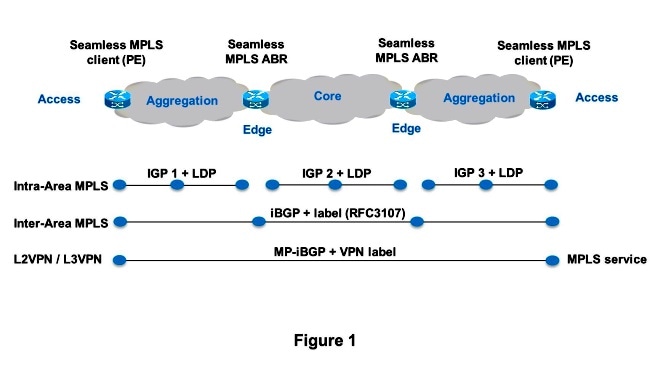
Figure 1 shows a network with three different areas: one core and two aggregation areas on the side. Each area runs its own IGP, with no redistribution between them on the Area Border Router (ABR). Use of BGP is needed in order to provide an end-to-end MPLS LSP. BGP advertises the loopbacks of the PE routers with a label across the whole domain, and provides an end-to-end LSP. BGP is deployed between the PEs and ABRs with RFC 3107, which means that BGP sends the IPv4 prefix + label (AFI/SAFI 1/4).
Since the core and aggregation parts of the network are integrated and end-to-end LSPs are provided, the Unified MPLS solution is also referred to as "Seamless MPLS."
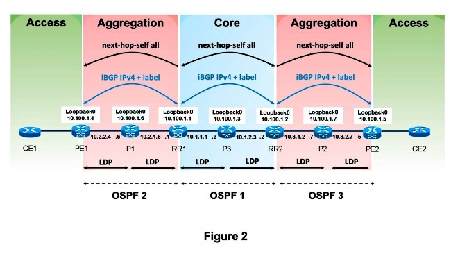
New technologies or protocols are not used here, only MPLS, Label Distribution Protocol (LDP), IGP, and BGP. Since you do not want to distribute the loopback prefixes of the PE routers from one part of the network into another part, you need to carry the prefixes in BGP. The Internal Border Gateway Protocol (iBGP) is used in one network, so the next hop address of the prefixes is the loopback prefixes of the PE routers, which is not known by the IGP in the other parts of the network. This means that the next hop address cannot be used to recurse to an IGP prefix. The trick is to make the ABR routers Route Reflectors (RR) and set the next hop to self, even for the reflected iBGP prefixes. In order for this to work, a new knob is needed.
Only the RRs need newer software to support this architecture. Since the RRs advertise the BGP prefixes with the next hop set to themselves, they assign a local MPLS label to the BGP prefixes. This means that in the data plane, the packets forwarded on these end-to-end LSPs have an extra MPLS label in the label stack. The RRs are in the forwarding path.
There are two possible scenarios:
- The ABR does not set the next hop to self for the prefixes advertised (reflected by BGP) by the ABR into the aggregation part of the network. Because of this, the ABR needs to redistribute the loopback prefixes of the ABRs from the core IGP into the aggregation IGP. If this is done, there is still scalability. Only the ABR loopback prefixes (from the core) need to be advertised into the aggregation part, not the loopback prefixes from the PE routers from the remote aggregation parts.
- The ABR sets the next hop to self for the prefixes advertised (reflected by BGP) by the ABR into the aggregation part. Because of this, the ABR does not need to redistribute the loopback prefixes of the ABRs from the core IGP into the aggregation IGP.
In both scenarios, the ABR sets the next hop to self for the prefixes advertised (reflected by BGP) by the ABR from the aggregation part of the network into the core part. If this is not done, the ABR needs to redistribute the loopback prefixes of the PEs from the aggregation IGP into the core IGP. If this is done, there is no scalability.
In order to set the next hop to self for reflected iBGP routes, you must configure the neighbor x.x.x.x next-hop-self all command.
Configure
This is the configuration of the PE routers and ABRs for scenario 2.
PE1

interface Loopback0
 ip address 10.100.1.4 255.255.255.255

!
interface Ethernet1/0
 no ip address
 xconnect 10.100.1.5 100 encapsulation mpls
!
router ospf 2
 network 10.2.0.0 0.0.255.255 area 0
 network 10.100.1.4 0.0.0.0 area 0
!
router bgp 1
 bgp log-neighbor-changes
 network 10.100.1.4 mask 255.255.255.255
 neighbor 10.100.1.1 remote-as 1
 neighbor 10.100.1.1 update-source Loopback0
 neighbor 10.100.1.1 send-label

RR1


interface Loopback0
 ip address 10.100.1.1 255.255.255.255
router ospf 1
 network 10.1.0.0 0.0.255.255 area 0
 network 10.100.1.1 0.0.0.0 area 0
!
router ospf 2
 redistribute ospf 1 subnets match internal route-map ospf1-into-ospf2
 network 10.2.0.0 0.0.255.255 area 0
!
router bgp 1
 bgp log-neighbor-changes
 neighbor 10.100.1.2 remote-as 1
 neighbor 10.100.1.2 update-source Loopback0
 neighbor 10.100.1.2 next-hop-self all
 neighbor 10.100.1.2  send-label
 neighbor 10.100.1.4 remote-as 1
 neighbor 10.100.1.4 update-source Loopback0
 neighbor 10.100.1.4 route-reflector-client
 neighbor 10.100.1.4 next-hop-self all
 neighbor 10.100.1.4 send-label

ip prefix-list prefix-list-ospf1-into-ospf2 seq 5 permit 10.100.1.1/32

route-map ospf1-into-ospf2 permit 10
 match ip address prefix-list prefix-list-ospf1-into-ospf2


RR2

interface Loopback0
 ip address 10.100.1.2 255.255.255.255

router ospf 1
 network 10.1.0.0 0.0.255.255 area 0
 network 10.100.1.2 0.0.0.0 area 0
!
router ospf 3
 redistribute ospf 1 subnets match internal route-map ospf1-into-ospf3
 network 10.3.0.0 0.0.255.255 area 0
!
router bgp 1
 bgp log-neighbor-changes
 neighbor 10.100.1.1 remote-as 1
 neighbor 10.100.1.1 update-source Loopback0
 neighbor 10.100.1.1 next-hop-self all
 neighbor 10.100.1.1 send-label
 neighbor 10.100.1.5 remote-as 1
 neighbor 10.100.1.5 update-source Loopback0
 neighbor 10.100.1.5 route-reflector-client
 neighbor 10.100.1.5 next-hop-self all
 neighbor 10.100.1.5 send-label

ip prefix-list prefix-list-ospf1-into-ospf3 seq 5 permit 10.100.1.2/32

route-map ospf1-into-ospf3 permit 10
 match ip address prefix-list prefix-list-ospf1-into-ospf3


PE2

interface Loopback0
 ip address 10.100.1.5 255.255.255.255

interface Ethernet1/0
 no ip address
 xconnect 10.100.1.4 100 encapsulation mpls

router ospf 3
 network 10.3.0.0 0.0.255.255 area 0
 network 10.100.1.5 0.0.0.0 area 0

router bgp 1
 bgp log-neighbor-changes
 network 10.100.1.5 mask 255.255.255.255
 neighbor 10.100.1.2 remote-as 1
 neighbor 10.100.1.2 update-source Loopback0
 neighbor 10.100.1.2 send-label
Verify
See Figure 2 in order to verify the control plane operation.

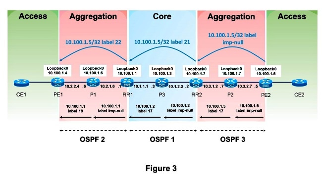
See Figure 3 in order to verify the MPLS label advertisements.

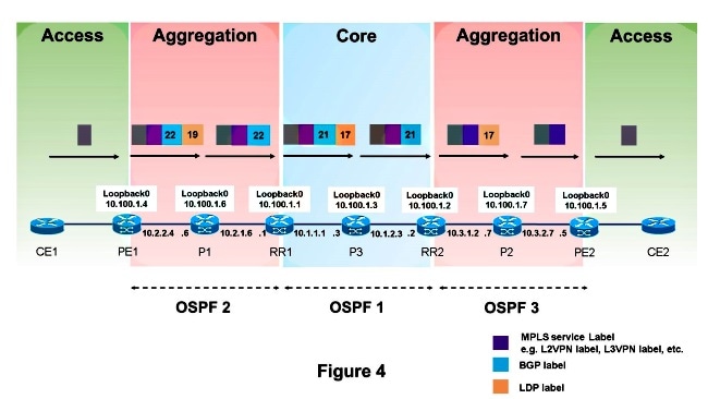
See Figure 4 in order to the verify the packet forwarding.

This is how packets are forwarded from PE1 to PE2. The loopback prefix of PE2 is 10.100.1.5/32, so that prefix is of interest.
PE1#show ip route 10.100.1.5

Routing entry for 10.100.1.5/32
  Known via "bgp 1", distance 200, metric 0, type internal
  Last update from 10.100.1.1 00:11:12 ago
  Routing Descriptor Blocks:
  * 10.100.1.1, from 10.100.1.1, 00:11:12 ago
    Route metric is 0, traffic share count is 1
    AS Hops 0
    MPLS label: 22


PE1#show ip cef 10.100.1.5
10.100.1.5/32
  nexthop 10.2.2.6 Ethernet0/0 label 19 22


PE1#show ip cef 10.100.1.5 detail
10.100.1.5/32, epoch 0, flags rib defined all labels
  1 RR source [no flags]
  recursive via 10.100.1.1 label 22
    nexthop 10.2.2.6 Ethernet0/0 label 19

PE1#show bgp ipv4 unicast labels

   Network          Next Hop      In label/Out label
   10.100.1.4/32    0.0.0.0         imp-null/nolabel
   10.100.1.5/32    10.100.1.1      nolabel/22


P1#show mpls forwarding-table labels 19 detail
Local      Outgoing   Prefix           Bytes Label   Outgoing   Next Hop
Label      Label      or Tunnel Id     Switched      interface
19         Pop Label  10.100.1.1/32    603468        Et1/0      10.2.1.1
        MAC/Encaps=14/14, MRU=1504, Label Stack{}
        AABBCC000101AABBCC0006018847
        No output feature configured


RR1#show mpls forwarding-table labels 22 detail
Local      Outgoing   Prefix           Bytes Label   Outgoing   Next Hop
Label      Label      or Tunnel Id     Switched      interface
22         21         10.100.1.5/32    575278        Et0/0      10.1.1.3
        MAC/Encaps=14/22, MRU=1496, Label Stack{17 21}
        AABBCC000300AABBCC0001008847 0001100000015000
        No output feature configured


RR1#show bgp ipv4 unicast labels
   Network          Next Hop      In label/Out label
   10.100.1.4/32    10.100.1.4      19/imp-null
   10.100.1.5/32    10.100.1.2      22/21


P3#show mpls forwarding-table labels 17 detail
Local      Outgoing   Prefix           Bytes Label   Outgoing   Next Hop
Label      Label      or Tunnel Id     Switched      interface
17         Pop Label  10.100.1.2/32    664306        Et1/0      10.1.2.2
        MAC/Encaps=14/14, MRU=1504, Label Stack{}
        AABBCC000201AABBCC0003018847
        No output feature configured


RR2#show mpls forwarding-table labels 21 detail
Local      Outgoing   Prefix           Bytes Label   Outgoing   Next Hop
Label      Label      or Tunnel Id     Switched      interface
21         17         10.100.1.5/32    615958        Et0/0      10.3.1.7
        MAC/Encaps=14/18, MRU=1500, Label Stack{17}
        AABBCC000700AABBCC0002008847 00011000
        No output feature configured


RR2#show bgp ipv4 unicast labels
   Network          Next Hop      In label/Out label
   10.100.1.4/32    10.100.1.1      22/19
   10.100.1.5/32    10.100.1.5      21/imp-null


P2#show mpls forwarding-table labels 17 detail
Local      Outgoing   Prefix           Bytes Label   Outgoing   Next Hop
Label      Label      or Tunnel Id     Switched      interface
17         Pop Label  10.100.1.5/32    639957        Et1/0      10.3.2.5
        MAC/Encaps=14/14, MRU=1504, Label Stack{}
        AABBCC000500AABBCC0007018847
        No output feature configured


PE1#trace
Protocol [ip]:
Target IP address: 10.100.1.5
Source address: 10.100.1.4
DSCP Value [0]:
Numeric display [n]:
Timeout in seconds [3]:
Probe count [3]:
Minimum Time to Live [1]:
Maximum Time to Live [30]:
Port Number [33434]:
Loose, Strict, Record, Timestamp, Verbose[none]:
Type escape sequence to abort.
Tracing the route to 10.100.1.5
VRF info: (vrf in name/id, vrf out name/id)
  1 10.2.2.6 [MPLS: Labels 19/22 Exp 0] 3 msec 3 msec 3 msec
  2 10.2.1.1 [MPLS: Label 22 Exp 0] 3 msec 3 msec 3 msec
  3 10.1.1.3 [MPLS: Labels 17/21 Exp 0] 3 msec 3 msec 2 msec
  4 10.1.2.2 [MPLS: Label 21 Exp 0] 2 msec 3 msec 2 msec
  5  *  *  *
  6 10.3.2.5 4 msec *  4 msec
P2#show ip route 10.100.1.4
% Subnet not in table
Troubleshoot
There is currently no specific troubleshooting information available for this configuration.
Related Information
Revision History
| Revision | Publish Date | Comments |
|---|---|---|
1.0 |
03-Jul-2013 |
Initial Release |
 Feedback