Total Network Configuration: RV260P with CBW and the Cisco Business Mobile App
Available Languages
Objective:
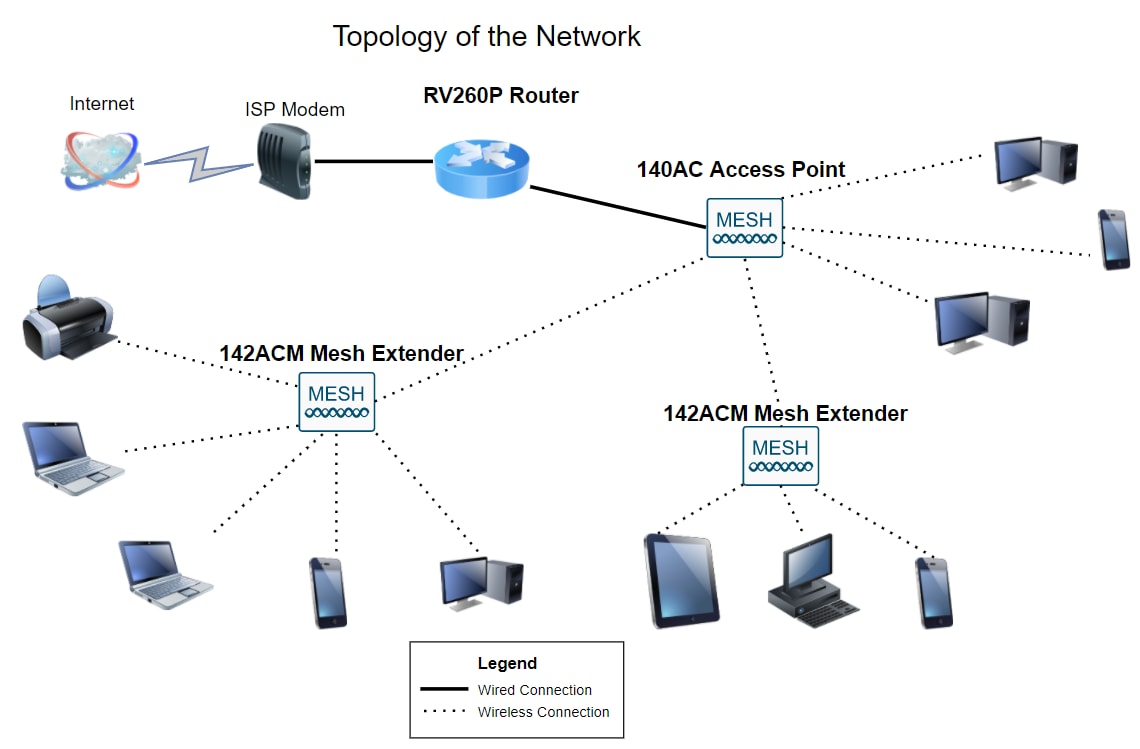
This guide will show you how to configure a wireless mesh network using an RV260P router, a CBW140AC access point, two CBW142ACM mesh extenders, and the Cisco Business Wireless application.
Topology:
Introduction
Here you are, ready to set up your new network. It’s an exciting day! In this scenario, we are using an RV260P router. This router provides Power over Ethernet (PoE) which allows you to plug a Cisco Business Wireless (CBW) 140AC into the router instead of a switch. The CBW140AC access point and the CBW142ACM mesh extenders will be used to create a wireless mesh network.
If you are unfamiliar with some of the terms used in this document or want more details about Mesh Networking, check out the following articles:
- Welcome to Cisco Business Wireless Mesh Networking
- Frequently Asked Questions (FAQ) for a Cisco Business Wireless Network
The mobile application is recommended as the easiest way to set basic configurations on CBW, however, not all features can be configured on the application. If you are new to the Cisco Business Wireless app, check out the following articles:
- Get Familiar with Cisco Business CB-Wireless-Mesh App
- Cisco Business Wireless: CBW App vs Web UI Features
If you prefer to use the Web UI when configuring your mesh wireless network, click to view the version that only uses the Web UI.
Are you ready? Let’s get to it!
Applicable Devices | Software Version
- RV260P | 1.0.0.17
- CBW140AC | 10.3.1.0
- CBW142ACM | 10.3.1.0 (at least one mesh extender is needed for the mesh network)
Table of Contents
Before you Get Started
- Make sure you have a current Internet connection for setup.
- Contact your ISP to find out any special instructions they have when using your RV260 router. Some ISPs offer gateways with built-in routers. If you have a gateway with an integrated router, you may have to disable the router and pass the Wide Area Network (WAN) IP address (the unique Internet protocol address that the Internet provider assigns to your account) and all network traffic through to your new router.
- Decide where to place the router. You will want an open area if possible. This may not be easy because you must connect the router to the broadband gateway (modem) from your Internet Service Provider (ISP).
Configure the RV260P Router
A router is essential in a network because it routes packets. It enables a computer to communicate with other computers that are not on the same network or subnet. A router accesses a routing table to determine where packets should be sent. The routing table lists destination addresses. Static and dynamic configurations can both be listed on the routing table in order to get packets to their specific destination.
Your RV260P comes with default settings that are optimized for many small businesses. However, your network demands or Internet Service Provider (ISP) might require you to modify a few of these settings. After you contact your ISP for the requirements, you can make changes using the Web User Interface (UI).
RV260P Out of the Box
Step 1
Connect the Ethernet cable from one of the RV260P LAN (Ethernet) ports to the Ethernet port on the computer. You will need an adapter if your computer doesn’t have an Ethernet port. The terminal must be in the same wired subnetwork as the RV260P to perform the initial configuration.
Step 2
Be sure to use the power adapter that is supplied with the RV260P. Using a different power adapter could damage the RV260P or cause USB dongles to fail. The power switch is on by default.
Connect the power adapter to the 12VDC port of the RV260P, but don’t plug it into power yet.
Step 3
Make sure your modem is also turned off.
Step 4
Use an Ethernet cable to connect your cable or DSL modem to the WAN port on the RV260P.
Step 5
Plug the other end of the RV260P adapter into an electrical outlet. This will power on the RV260. Plug the modem back in so it can power up as well. The power light on the front panel is solid green when the power adapter is connected properly and the RV260P is finished booting.
Set Up the Router
The prep work is done, now it’s time to do some configurations! To launch the Web UI, follow these steps:
Step 1
If your computer is configured to become a Dynamic Host Configuration Protocol (DHCP) client, an IP address in the 192.168.1.x range is assigned to the PC. DHCP automates the process of assigning IP addresses, subnet masks, default gateways, and other settings to computers. Computers must be set to participate in the DHCP process to obtain an address. This is done by selecting to obtain an IP address automatically in the properties of TCP/IP on the computer.
Step 2
Open a web browser such as Safari, Internet Explorer, or Firefox. In the address bar, enter the default IP address of the RV260P, 192.168.1.1.

Step 3
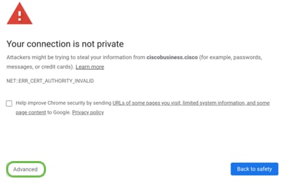
The browser might issue a warning that the website is untrusted. Continue to the website. If you are not connected, jump down to Troubleshooting the Internet Connection.
Step 4
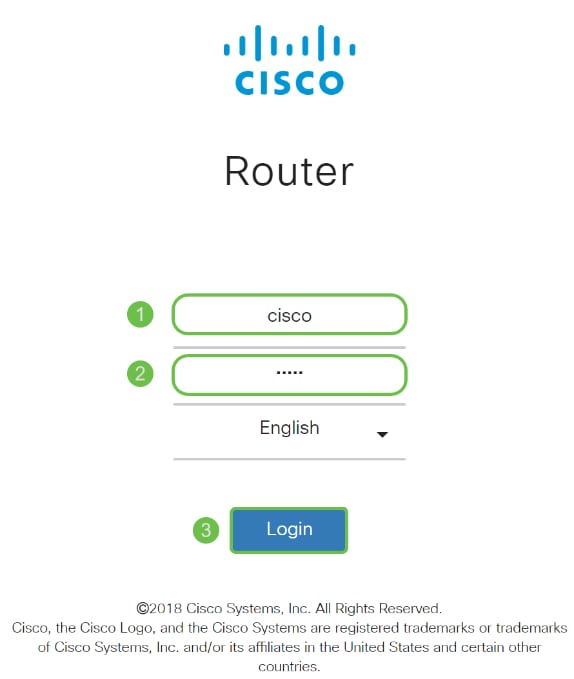
When the sign-in page appears, enter the default username cisco and the default password cisco. Both the username and password are case sensitive.
Step 5
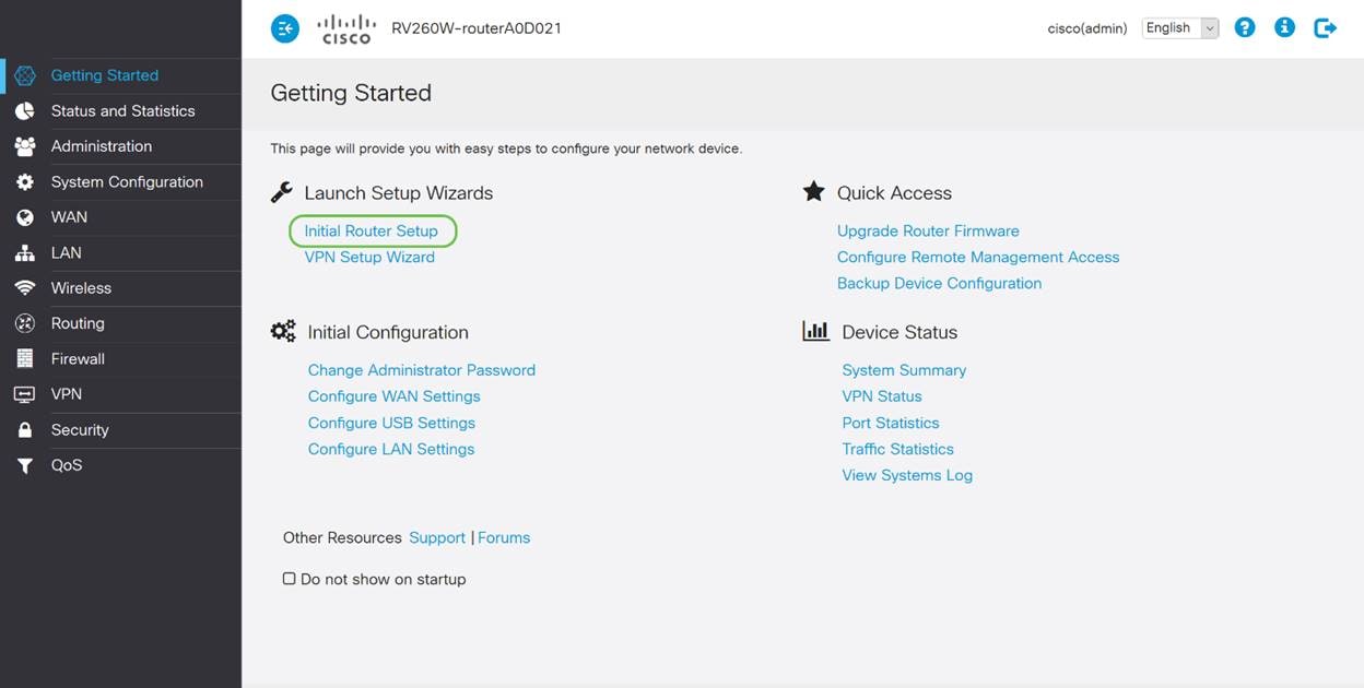
Click Login. The Getting Started page appears. Now that you have confirmed the connection and logged in to the router, jump to the Initial Configuration section of this article.
Troubleshooting the Internet Connection
Dang it, if you are reading this you are probably having trouble connecting to the Internet or the Web UI. One of these solutions should help.
On your connected Windows OS, you can test your network connection by opening the command prompt. Enter ping 192.168.1.1 (the default IP address of the router). If the request times out, you are not able to communicate with the router. If you receive a response, you have connectivity and can move on to the Initial Configuration section of this article.
If connectivity is not happening, you can check out Troubleshooting on RV160 and RV260 Routers.
Some other things to try:
- Verify that your web browser is not set to Work Offline.
- Check the local area network connection settings for your Ethernet adapter. The PC should obtain an IP address through DHCP. Alternatively, the PC can have a static IP address in the 192.168.1.x range with the default gateway set to 192.168.1.1 (the default IP address of the RV260P). To connect, you may need to modify the network settings of the RV260P. If you are using Windows 10, check out Windows 10 directions to modify the network settings of the RV260P.
- If you have existing equipment occupying the 192.168.1.1 IP address, you'll need to resolve this conflict for the network to operate. More on this at the end of this section, or click here to be taken there directly.
- Reset the modem and the RV260P by powering off both devices. Next, power on the modem and let it sit idle for about 2 minutes. Then power on the RV260P. You should now receive a WAN IP address.
- If you have a DSL modem, ask your ISP to put the DSL modem into bridge mode.
Initial Configuration
We recommend that you go through the Initial Setup Wizard steps listed in this section. You can change these settings at any time. If there are articles for a specific setting, they will be listed at the end of the step.
Step 1
Click Initial Setup Wizard from the Getting Started Page.
Step 2
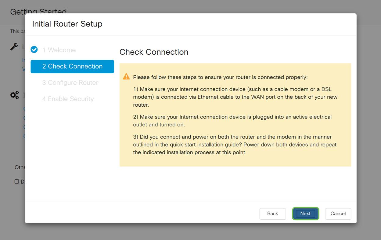
This step confirms the cables are connected. Since you confirmed this already, click Next.

Step 3
This step covers basic steps to make sure your router is connected. Since you have already confirmed this, click Next.
Step 4
The next screen displays your options for assigning IP addresses to your router. You need to select DHCP in this scenario. Click Next.

Although you must use DHCP for this initial setup, you can select to Learn more about the different connection types toward the bottom of your screen the future reference. For more details on this, check out:

Step 5
Next, you will be prompted to set your router time settings. This is important because it enables precision when reviewing logs or troubleshooting events. Select your Time Zone and then click Next.

Step 6
Next, you will select what MAC addresses to assign to devices. Most often, you will use the default address. Click Next.

Step 7
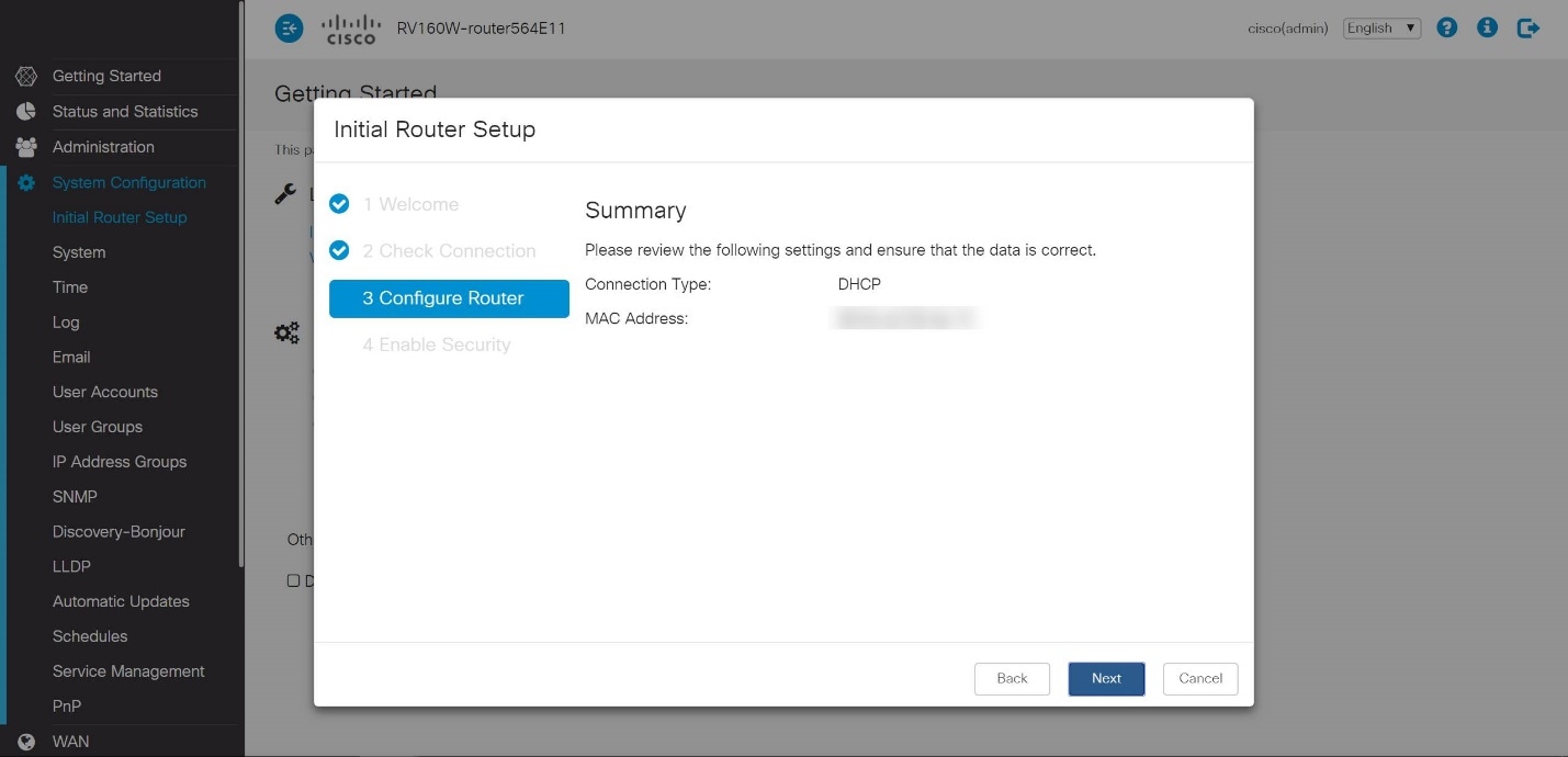
The following page is a summary of the selected options. Review and click Next if satisfied.
Step 8
For the next step, you will select a password to use when logging into the router. The standard for passwords is to contain at least 8 characters (both upper and lower case) and include numbers. Enter a password that conforms with the strength requirements. Click Next. Take note of your password for future logins.

It is not recommended that you select Disable Password Strength Enforcement. This option would let you select a password as simple as 123, which would be as easy as 1-2-3 for malicious actors to crack.
Step 9
Click the Save icon.

Upgrade Firmware if Needed
This is important, don’t skip it!
Step 1
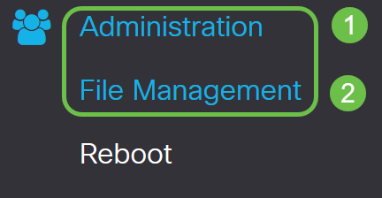
Choose Administration > File Management.
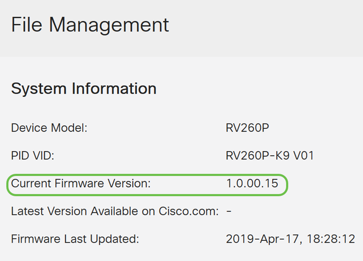
In the System Information area, the following sub-areas describe the following:
- Device Model - Displays the model of your device.
- PID VID - Product ID and Vendor ID of the router.
- Current Firmware Version - Firmware that is currently running on the device.
- Latest Version Available on Cisco.com - Latest version of the software available on the Cisco website.
- Firmware last updated - Date and time of the last firmware update made on the router.
Step 2
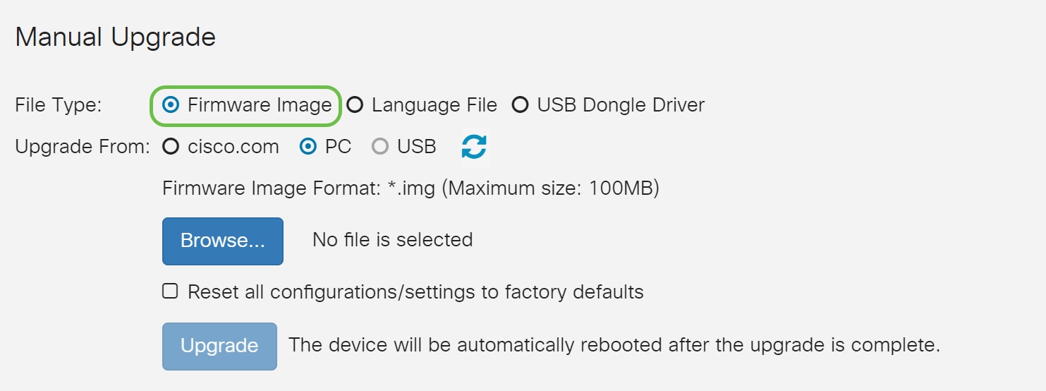
Under Manual Upgrade section, click on the Firmware Image radio button for File Type.
Step 3
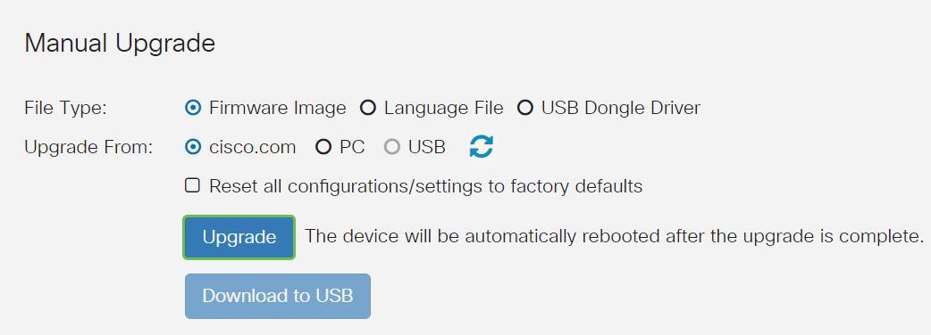
On the Manual Upgrade page, click on a radio button to select cisco.com. There are a few other options for this, but this is the easiest way to do an upgrade. This process installs the latest upgrade file directly from the Cisco Software Downloads webpage.

Step 4
Click on Upgrade.
Step 5
Click Yes in the confirmation window to continue.

The update process needs to run without interruption. You will get the following message on the screen while the upgrade is in progress.

Once the upgrade has been completed, a notification window will pop-up to inform you that the router will be Restarting with a countdown of the estimated time for the process to finish. Following this, you will be logged out.

Step 6
Log back into the web-based utility to verify that the router firmware has been upgraded, scroll to the System Information. The Current Firmware Version area should now display the upgraded firmware version.

Congratulations, your basic settings on your router are complete! You have some configuration options moving forward.
We encourage you to keep scrolling through the article to learn more about these options and if they apply to you. If you prefer, you can click any of the hyperlinks to jump to a section instead.
- Virtual Local Area Networks (VLANs)
- Edit IP Address
- Add static IP addresses
- I’m ready to configure the Mesh Wireless portion of my network
Configure VLANs (Optional)
A Virtual Local Area Network (VLAN) allows you to logically segment a Local Area Network (LAN) into different broadcast domains. In scenarios where sensitive data may be broadcast on a network, VLANs can be created to enhance security by designating a broadcast to a specific VLAN. VLANs can also be used to enhance performance by reducing the need to send broadcasts and multicasts to unnecessary destinations. You can create a VLAN, but this has no effect until the VLAN is attached to at least one port, either manually or dynamically. Ports must always belong to one or more VLANs.
If you do not want to create VLANs, you can skip to the next section.
Step 1
Navigate to LAN > VLAN Settings.

Step 2
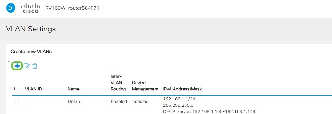
Click Add to create a new VLAN.
Step 3
Enter the VLAN ID that you want to create and a Name for it. The VLAN ID range is from 1-4093.
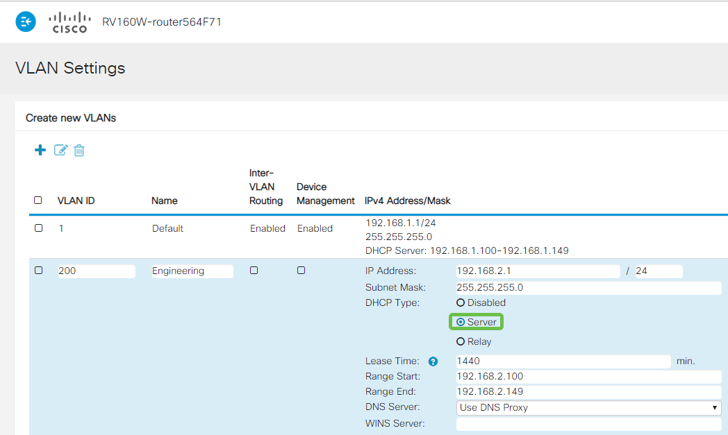
We entered 200 as our VLAN ID and Engineering as the Name for the VLAN.

Step 4
Uncheck the Enabled box for both Inter-VLAN Routing and Device Management if desired.
Inter-VLAN routing is used to route packets from one VLAN to another VLAN. In general, this is not recommended for guest networks as you will want to isolate guest users it leaves VLANs less secure. There are times when it may be necessary for VLANs to route between each other. If this is the case, check out Inter-VLAN Routing on an RV34x Router with Targeted ACL Restrictions to configure specific traffic that you allow between VLANs.
Device Management is the software that allows you to use your browser to log into the Web UI of the RV260P, from the VLAN, and manage the RV260P. This should also be disabled on Guest networks.
In this example, we did not enable either the Inter-VLAN Routing or Device Management to keep the VLAN more secure.

Step 5
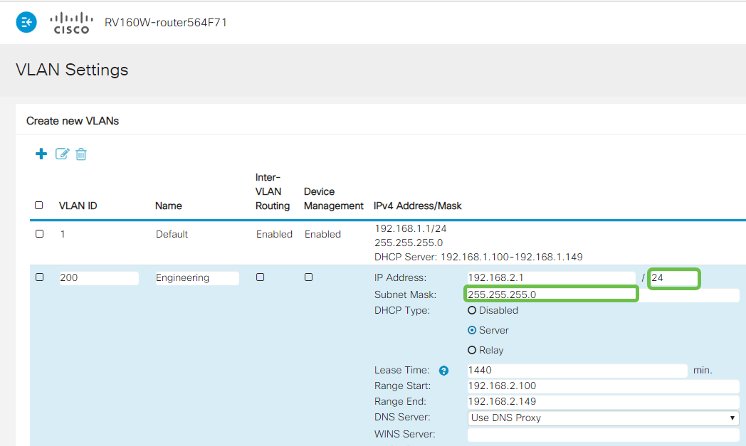
The private IPv4 address will auto-populate in the IP Address field. You can adjust this if you choose. In this example, the subnet has 192.168.2.100-192.168.2.149 IP addresses available for DHCP. 192.168.2.1-192.168.2.99, and 192.168.2.150-192.168.2.254 are available for static IP addresses.

Step 6
The subnet mask under Subnet Mask will auto-populate. If you make changes, this will automatically adjust the field.
For this demonstration, we will be leaving the Subnet Mask as 255.255.255.0 or /24.
Step 7
Select a Dynamic Host Configuration Protocol (DHCP) Type. The following options are:
Disabled – Disables the DHCP IPv4 server on VLAN. This is recommended in a test environment. In this scenario, all IP addresses would need to be manually configured and all communication would be internal.
Server - This is the most often used option.
- Lease Time – Enter a time value of 5 to 43,200 minutes. The default is 1440 minutes (equal to 24 hours).
- Range Start and Range End – Enter the range start and end of IP addresses that can be assigned dynamically.
- DNS Server – Select to use a DNS server as a proxy, or from ISP from the drop-down list.
- WINS Server – Enter the WINS server name.
- DHCP Options:
- Option 66 – Enter the IP address of the TFTP server.
- Option 150 – Enter the IP address of a list of TFTP servers.
- Option 67 – Enter the configuration filename.
- Relay – Enter the remote DHCP server IPv4 address to configure the DHCP relay agent. This is a more advanced configuration.
Step 8
Click Apply to create the new VLAN.

Assign VLANs to Ports
16 VLANs can be configured on the RV260, with one VLAN for the Wide Area Network (WAN). VLANs that are not on a port should be Excluded. This keeps the traffic on that port exclusively for the VLAN/VLANs the user specifically assigned. It is considered a best practice.
Ports can be set to be an Access Port or a Trunk Port:
- Access Port - Assigned one VLAN. Untagged frames are passed.
- Trunk Port - Can carry more than one VLAN. 802.1q. Trunking allows for a native VLAN to be Untagged. VLANs that you don’t want on the Trunk should be Excluded.
One VLAN assigned its own port:
- Considered an Access port.
- The VLAN that is assigned this port should be labeled Untagged.
- All other VLANs should be labeled Excluded for that port.
Two or more VLANs that share one port:
- Considered a Trunk Port.
- One of the VLANs can be labeled Untagged.
- The rest of the VLANs that are part of the Trunk Port should be labeled Tagged.
- The VLANs that are not part of the Trunk Port should be labeled Excluded for that port.
Note: In this example, there are no trunks.
Step 9
Select the VLAN IDs to edit. Click Edit.
In this example, we have selected VLAN 1 and VLAN 200.

Step 10
Click Edit to assign a VLAN to a LAN port and specify each setting as Tagged, Untagged, or Excluded.
In this example, on LAN1 we assigned VLAN 1 as Untagged and VLAN 200 as Excluded. For LAN2 we assigned VLAN 1 as Excluded and VLAN 200 as Untagged.

Step 11
Click Apply to save the configuration.

You should now have successfully created a new VLAN and configured VLANs to ports on the RV260. Repeat the process to create the other VLANs. For example, VLAN300 would be created for Marketing with a subnet of 192.168.3.x and VLAN400 would be created for Accounting with a subnet of 192.168.4.x.
That’s the basics of VLANs. Click on the hyperlink to learn more about VLAN Best Practices and Security Tips for Cisco Business Routers.
Edit an IP address (Optional)
After completing the Initial Setup Wizard, you can set a static IP address on the router by editing the VLAN settings. Skip re-running the initial setup wizard, to perform this change follow the steps below.
If you don’t need to edit an IP address, you can move to the next section of this article.
Step 1
In the left-hand menu-bar click the LAN button and then click VLAN Settings.

Step 2
Then select the VLAN that contains your routing device, then click the edit icon.

Step 3
Enter your desired static IP address and click Apply in the upper-right hand corner.

Step 4 (Optional)
If your router is not the DHCP server/device assigning IP addresses, you can use the DHCP Relay feature to direct DHCP requests to a specific IP address. The IP address is likely to be the router connected to the WAN/Internet.

Add a Static IP (Optional)
If you would like a certain device to be reachable to other VLANs, you can give that device a static IP address and create an access rule to make it accessible. This only works if Inter-VLAN routing is enabled.
If you don’t need to add a static IP address, you can move to the next section of this article to configure the Access Points.
Step 1
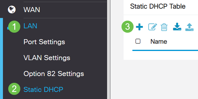
Navigate to LAN > Static DHCP. Click on the plus icon.
Step 2
Add the Static DHCP information for the device. In this example, the device is a printer.

If you need more information on setting static IP addresses, check out Best Practices for Setting Static IP Addresses on Cisco Business Hardware.
Congratulations, you have completed the configuration of your RV260P router. We will now configure your Cisco Business Wireless devices.
Configure the CBW140AC
CBW140AC Out of the Box
Start by plugging an Ethernet cable from the PoE port on your CBW140AC to a PoE port on the RV260P. The first 4 ports on the RV260P can supply PoE, so any of them can be used.
Check the status of the indicator lights. The access point will take about 10 minutes to boot. The LED will blink green in multiple patterns, alternating rapidly through green, red, and amber before turning green again. There may be small variations in the LED color intensity and hue from unit to unit. When the LED light is blinking green, proceed to the next step.
The PoE Ethernet uplink port on the Primary AP can ONLY be used to provide an uplink to the LAN, and NOT to connect to any other Primary capable or mesh extender devices.
If your access point isn’t new, out of the box, make sure it is reset to factory default settings for the CiscoBusiness-Setup SSID to show up in your Wi-Fi options. For assistance with this, check out How to Reboot and Reset to Factory Default Settings on RV160 and RV260 Routers.
Set Up the 140AC Mobile Application Wireless Access Point
In this section, you will be using the mobile application to set up the Mobile Application Wireless Access point.
On the back of the 140AC, plug the cable that came with the AP into the yellow PoE plug your 140 AC. Plug the other end into one of the RV260P LAN ports.
If you have trouble connecting, refer to the Wireless Troubleshooting Tips section of this article.
Step 1
Download the Cisco Business Wireless App available on Google Play or the Apple App Store on your mobile device. You will need one of the following Operating Systems:
- Android version 5.0 or above
- iOS version 8.0 or above
Step 2
Open the Cisco Business Wireless Application on your mobile device.

Step 3
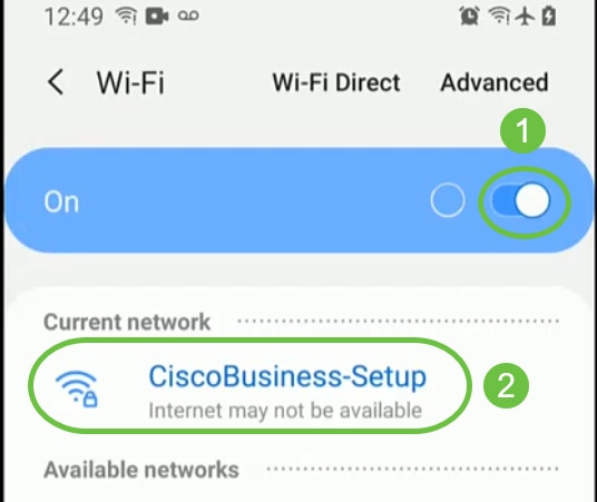
Connect to the CiscoBusiness-Setup wireless network on your mobile device. The passphrase is cisco123.

Step 4
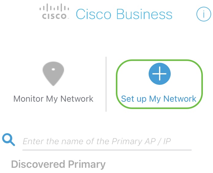
The app automatically detects the mobile network. Select Set up My Network.
Step 5
To set up the network enter the following:
- Create admin username
- Create admin password
- Confirm admin password by reentering it
- (Optional) Check the checkbox to Show Password.
Select Get Started.
Step 6
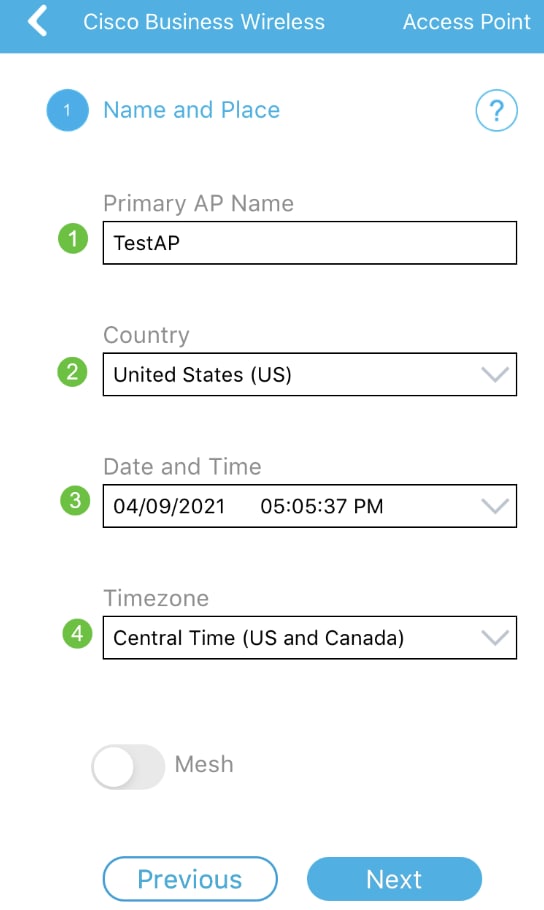
To configure Name and Place, accurately enter the following information. If you enter conflicting information, it can lead to unpredictable behavior.
- Mobile Application AP Name for your wireless network.
- Country
- Date
- Time
- Timezone

Step 7
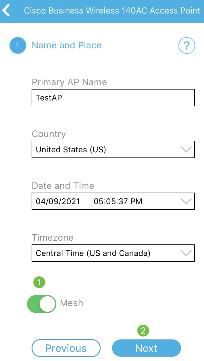
Turn on the toggle for Mesh. Click Next.
Step 8
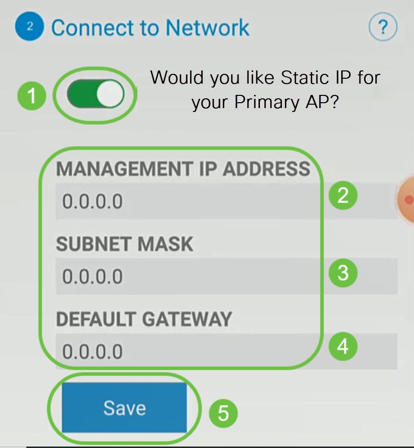
(Optional) You can choose to enable Static IP for your Mobile Application AP for management purposes. If not, your DHCP server will assign an IP address. If you do not wish to configure static IP for your access point, click Next.

Alternatively, to Connect to Network:
Select Static IP for your Mobile Application AP. By default, this option is disabled.
- Enter the Management IP Address
- Subnet Mask
- Default Gateway
Click Save.
Step 9
Configure the Wireless Network by entering the following:
- Network Name/SSID
- Security
- Passphrase
- Confirm passphrase
- (Optional) Check Show Passphrase
Click Next.

Wi-Fi protected Access (WPA) version 2 (WPA2), is the current standard for Wi-Fi security.
Step 10
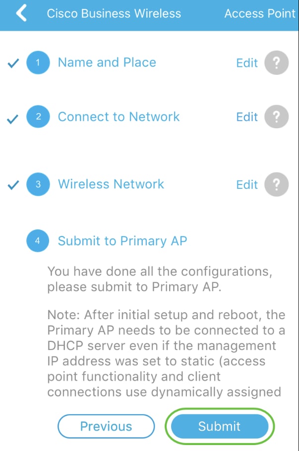
To confirm settings on the Submit to Mobile Application AP screen, click Submit.
Step 11
Wait for the reboot to complete.

The reboot can take up to 10 minutes. During a reboot, the LED in the access point will go through multiple color patterns. When the LED is blinking green, proceed to the next step. If the LED does not get past the red flashing pattern, it indicates that there is no DHCP server in your network. Ensure that the AP is connected to a switch or a router with a DHCP server.
Step 12
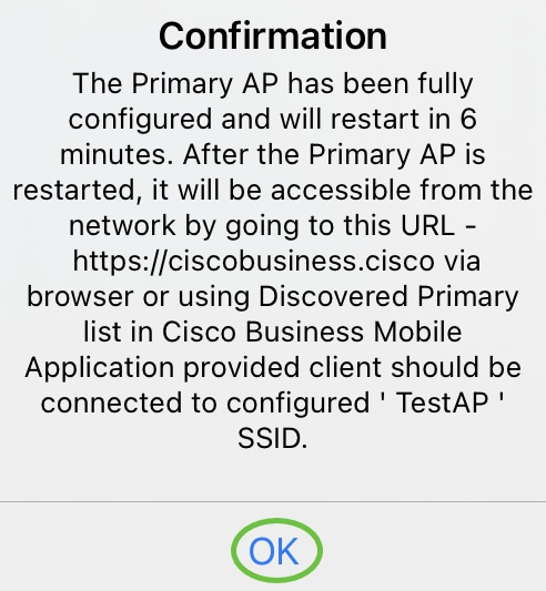
You will see the following Confirmation screen. Click OK.
Step 13
Close the app, connect to your newly created wireless network, and relaunch it to successfully complete the first part of your wireless network.
Wireless Troubleshooting Tips
If you have any issues, check out the following tips:
- Make sure the correct Service Set Identifier (SSID) is selected. This is the name that you created for the wireless network.
- Disconnect any VPN for either the mobile app or on a laptop. You might even be connected to a VPN that your mobile service provider uses that you might not even know. For example, an Android (Pixel 3) phone with Google Fi as a service provider there is a built-in VPN that auto-connects without notification. This would need to be disabled to find the Mobile Application AP.
- Log into the Mobile Application AP with https://<IP address of the Mobile Application AP>.
- Once you do the initial setup, be sure https:// is being used whether you are logging into ciscobusiness.cisco or by entering the IP address into your web browser. Depending on your settings, your computer may have auto-populated with http:// since that is what you used the very first time you logged in.
- To help with problems related to accessing the Web UI or browser issues during the use of the AP, in the web browser (Firefox in this case) click on the Open menu, go to Help > Troubleshooting Information and click on Refresh Firefox.
Configure the CBW142ACM Mesh Extenders
You are in the home stretch of setting up this network, you just need to add your mesh extenders!
Log into the Cisco Business app on your mobile device.
Step 1
Navigate to Devices. Double-check that Mesh is enabled.

Step 2
You must enter the MAC address of all Mesh Extenders that you want to use in the mesh network with the Mobile Application AP. To add the MAC address, click on Add Mesh Extenders from the menu.

Step 3
You can add the MAC address by either scanning a QR code or by manually entering the MAC address. In this example, Scan a QR code is selected.

Step 4
A QR code reader will appear to scan the QR code.

You will see the following screen once the QR code of the Mesh Extender has been scanned.

Step 5 (Optional)
If you prefer, enter a Description for Mesh Extender. Click OK.

Step 6
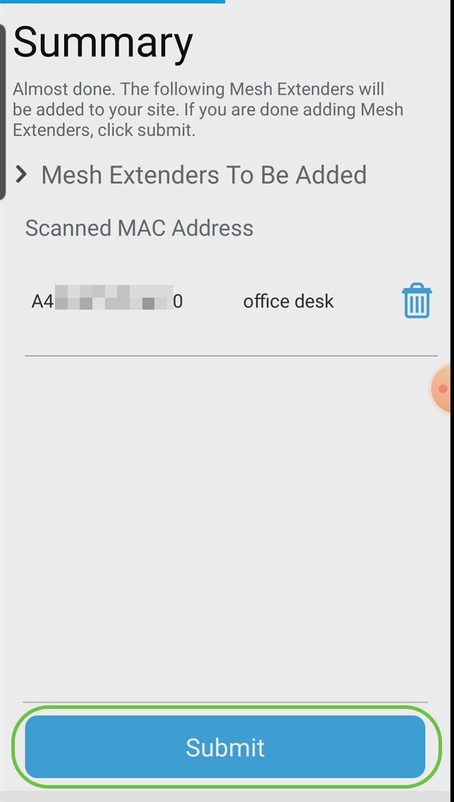
Review the Summary and click Submit.
Step 7
Click on Add More Mesh Extenders to add other mesh extenders to your network. Once your mesh extenders have all been added, click Done.

Repeat for each mesh extender.
You now have the basic settings ready to roll. Before you move on, make sure you check and update software if needed.
Check and Update Software on the Mobile App
Updating software is extremely important, so don’t skip this part!
Step 1
On your mobile app, under the More tab, click the Check for update button. Follow the prompts to update the software to the latest version.

Step 2
You will see the download progress as it loads.

Step 3
A pop-up confirmation will notify you of the conclusion of the software upgrade. Click OK.
Create WLANs using the Mobile App
This section allows you to create Wireless Local Area Networks (WLANs).
Step 1
Open the Cisco Business Wireless App.

Step 2
Connect to your Cisco Business wireless network on your mobile. Log into the application. Click on the WLAN icon at the top of the page.

Step 3
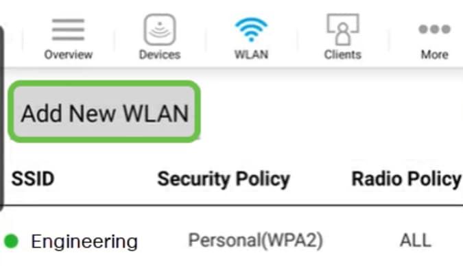
The Add New WLAN screen opens. You will see the existing WLANs. Select Add New WLAN.
Step 4
Enter a Profile Name and SSID. Fill in the rest of the fields or leave at the default settings. If you enabled Application Visibility Control, you will have other configurations explained in Step 6. Click Next.

Step 5 (Optional)
If you enabled Application Visibility Control in step 4, you may configure other settings, including a Guest Network, The details for this can be found in the next section. Captive Network Assistant, Security Type, Passphrase, and Password Expiry can be added here as well. When you have added all configurations, click Next.
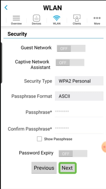
When using the mobile application, the only options for Security Type are Open or WPA2 Personal. For more advanced options, log into the Web UI of the Mobile Application AP instead.
Step 6 (Optional)
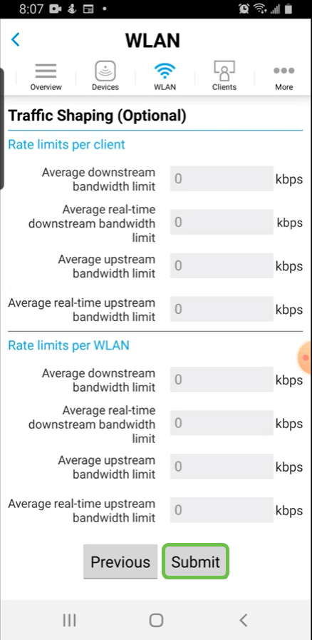
This screen gives you the options for Traffic Shaping. In this example, no traffic shaping has been configured. Click Submit.
Step 7
You will see a confirmation pop-up. Click Ok.

Step 8
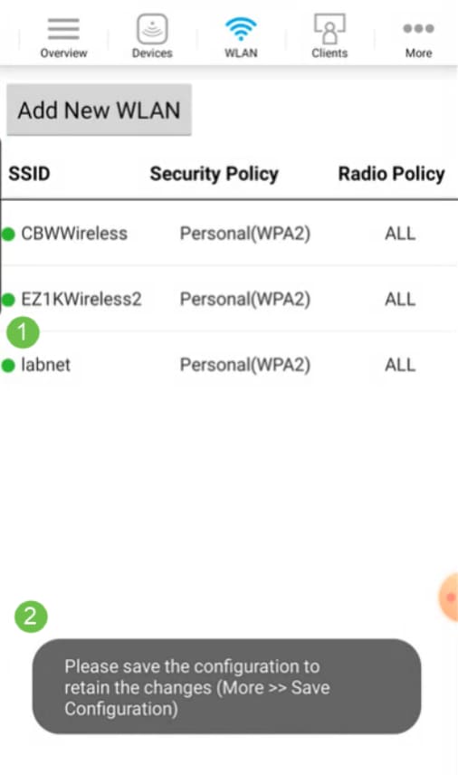
You will see the New WLAN added to the network as well as a reminder to save the configuration.
Step 9
Save your configuration by clicking the More tab and then select Save Configuration from the drop-down menu.

Create a Guest WLAN using the Mobile App
Step 1
Connect to your Cisco Business wireless network on your mobile device. Log into the application.

Step 2
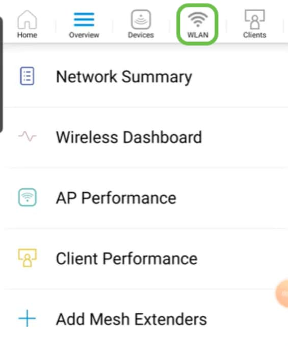
Click on the WLAN icon at the top of the page.
Step 3
The Add New WLAN screen opens. You will see any existing WLANs. Select Add New WLAN.

Step 4
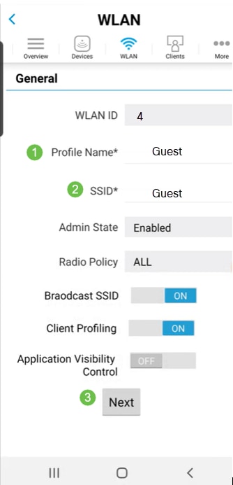
Enter a Profile Name and SSID. Fill in the rest of the fields or leave at the default settings. Click Next.
Step 5
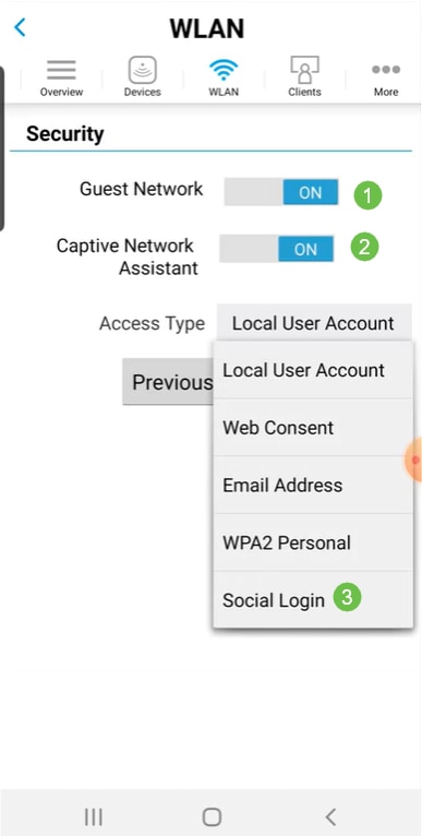
Turn on Guest Network. In this example, Captive Network Assistant is also toggled on, but this is optional. You have options for Access Type. In this case, Social Login is selected.
Step 6
This screen gives you the options for Traffic Shaping (Optional). In this example, no traffic shaping has been configured. Click Submit.

Step 7
You will see a confirmation pop-up. Click Ok.

Step 8
Save your configuration by clicking the More tab and then select Save Configuration from the drop-down menu.

Conclusion
You now have a complete set up for your network. Take a minute to celebrate and then get to work!
If you want to add Application Profiling or Client Profiling to your wireless mesh network, you will want to use the Web User Interface (UI). Click to set up these features.
We want the best for our customers, so you have any comments or suggestions regarding this topic, please send us an email to the Cisco Content Team.
If you would like to read other articles and documentation, check out the support pages for your hardware:
- Cisco RV260P VPN Router with PoE
- Cisco Business 140AC Access Point
- Cisco Business 142ACM Mesh Extender
Revision History
| Revision | Publish Date | Comments |
|---|---|---|
1.0 |
28-Oct-2020 |
Initial Release |
Contact Cisco
- Open a Support Case

- (Requires a Cisco Service Contract)
 Feedback