Troubleshoot Packet Flow in Catalyst 6500 Series VSS 1440
Available Languages
Contents
Introduction
This document provides guidelines to troubleshoot packet flow in a Virtual Switching System (VSS) network. While the example focuses on troubleshooting a network with VSS, the general principles shown can help in any network designed with redundant links.
Prerequisites
Requirements
Cisco recommends that you have knowledge of these topics:
Components Used
The information in this document is based on the Cisco Catalyst 6500 series switches with Supervisor VS-S720-10G-3C/XL that runs Cisco IOS® Software Release 12.2(33)SXH1 or later.
The information in this document was created from the devices in a specific lab environment. If your network is live, make sure that you understand the potential impact of any command.
Conventions
Refer to Cisco Technical Tips Conventions for more information on document conventions.
Background Information
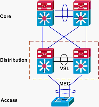
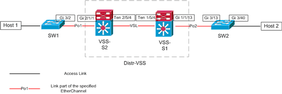
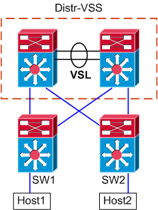
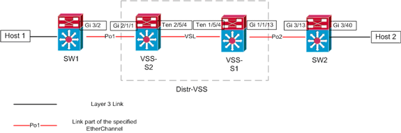
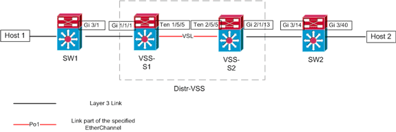
Refer to the network diagram for a typical network design utilizing VSS. When two Cisco switches are configured for VSS, they appear to the network as a single logical switch. In order to achieve redundancy, each node connected to the virtual switch should include at least one link to each physical chassis. The preferred method to utilize the redundant links is via multi-chassis etherchannel (MEC), but it is also acceptable to use equal-cost multipath (ECMP). MEC is the preferred connection method over ECMP because it can achieve faster unicast and multicast convergence times when one switch fails.
For more information, refer to the Upstream Link Recovery section of Cisco Catalyst 6500 Virtual Switching System Deployment Best Practices.
The virtualized nature of VSS creates a need to use new troubleshooting tools to trace the path of a packet in the network. Well known packet-path troubleshooting methods, such as looking at the MAC-address table or the routing table to determine next-hop, are not as useful with VSS networks as they will either return a Port-channel interface or multiple next-hop interfaces. The purpose of this document is to show which Cisco CLI commands available on the Catalyst 6500 platform can be used to gather more useful data about the path of a packet.
Network Diagram
This document uses this network setup:
Understanding Etherchannels on Catalyst 6500 Switches
Determine Load Balancing Algorithm
In all Cisco Catalyst switches, etherchannel links are selected based on a hash of certain fields in the packet headers, such as source and destination MAC, IP, or Layer 4 port number. Because this information is the same for all packets in a particular flow, etherchannel load balancing is sometimes referred to as flow-based.
On the Catalyst 6500 switch, the fields are used for this hash can be found with the show etherchannel load-balance command.
PFC-3B#show etherchannel load-balance
EtherChannel Load-Balancing Configuration:
        src-dst-ip
        mpls label-ip

EtherChannel Load-Balancing Addresses Used Per-Protocol:
Non-IP: Source XOR Destination MAC address
  IPv4: Source XOR Destination IP address
  IPv6: Source XOR Destination IP address
  MPLS: Label or IP
Here, it is shown that non-IP traffic such as IPX and Appletalk is hashed based on source and destination MAC address, and IPv4 and IPv6 traffic is hashed based on source and destination IP address. Hashing for MPLS packets is outside the scope of this document. The above settings are the defaults on the Catalyst 6500.
No other load-balance configuration options are available for IPv6 or Non-IP packets. However, other possible load-balance configurations for IPv4 packets are shown here:
-
Destination IP
-
Destination MAC
-
Destination Layer 4 Port
-
Mixed Destination IP and Layer 4 Port (PFC-3C only)
-
Source and Destination IP
-
Source and Destination MAC
-
Source and Destination Layer 4 Port
-
Mixed Source and Destination IP and Layer 4 Port (PFC-3C only)
-
Source IP
-
Source MAC
-
Source Layer 4 Port
-
Mixed Source IP and Layer 4 Port (PFC-3C only)
The etherchannel load-balance configuration can be changed via the port-channel load-balance command.
SW1(config)#port-channel load-balance ?
  dst-ip                 Dst IP Addr
  dst-mac                Dst Mac Addr
  dst-mixed-ip-port      Dst IP Addr and TCP/UDP Port
  dst-port               Dst TCP/UDP Port
  mpls                   Load Balancing for MPLS packets
  src-dst-ip             Src XOR Dst IP Addr
  src-dst-mac            Src XOR Dst Mac Addr
  src-dst-mixed-ip-port  Src XOR Dst IP Addr and TCP/UDP Port
  src-dst-port           Src XOR Dst TCP/UDP Port
  src-ip                 Src IP Addr
  src-mac                Src Mac Addr
  src-mixed-ip-port      Src IP Addr and TCP/UDP Port
  src-port               Src TCP/UDP Port
It is also important to note that the load-balancing algorithm was changed slightly with the introduction of PFC-3C(XL), which is found on the Supervisor 720-10GE. On the PFC-3C, the hash algorithm always takes VLAN into account in addition to the configured fields for IPv4 and IPv6 packets.
For instance, in the default configuration of src-dst-ip enhanced (shown below), the PFC takes source and destination IP as well as VLAN into account in order to calculate the hash value. Note that the VLAN used as the input should be the ingress VLAN of the packet. If the ingress interface is configured as Layer 3, the internal VLAN for that interface must be input as found by the show vlan internal usage command.
PFC-3C#show etherchannel load-balance
EtherChannel Load-Balancing Configuration:
        src-dst-ip enhanced
        mpls label-ip

EtherChannel Load-Balancing Addresses Used Per-Protocol:
Non-IP: Source XOR Destination MAC address
  IPv4: Source XOR Destination IP address
  IPv6: Source XOR Destination IP address
  MPLS: Label or IP
Determining Egress Interface – Standalone Catalyst 6500
Once the load balancing algorithm for the system is determined, this CLI can be used to determine the physical interface within an etherchannel selected for a particular packet (available only in version 12.2(33)SXH and later).
Router#show etherchannel load-balance hash-result interface port-channel 1 ?
  ip      IP address
  ipv6    IPv6
  l4port  Layer 4 port number
  mac     Mac address
  mixed   Mixed mode: IP address and Layer 4 port number
  mpls    MPLS
The previous command must be used with care, as it does not verify that the data input matches the data used in the load-balancing algorithm. If either too much or too little information is entered into this CLI, the prompt returns a physical interface. However, the interface returned might not be correct. These are some examples of the command being used properly:
Note: Some of the commands are moved to second lines due to space constraints.
On PFC-3B system with src-dst-ip algorithm:
PFC-3B#show etherchannel load-balance hash-result interface port-channel
1 ip 10.1.1.1 10.2.2.2

Computed RBH: 0x1
Would select Gig3/2 of Po1
On PFC-3C system with src-dst-ip enhanced algorithm:
PFC-3C#show etherchannel load-balance hash-result interface port-channel
1 ip 10.1.1.1 vlan 10 10.2.2.2

Computed RBH: 0x1
Would select Gig3/2 of Po1
On PFC-3C system with src-dst-ip enhanced algorithm and ingress interface is Layer 3:
PFC-3C#show vlan internal usage | include Port-channel 2

1013 Port-channel 2
PFC-3C#
PFC-3C#show etherchannel load-balance hash-result interface port-channel 1
ip 10.1.1.1 vlan 1013 10.2.2.2

Computed RBH: 0x1
Would select Gig3/2 of Po1
On PFC-3CXL system with src-dst-mixed-ip-port enhanced algorithm:
PFC-3CXL#show etherchannel load-balance hash-result interface port-channel
1 mixed 10.1.1.1 1600 10 10.2.2.2 80

Computed RBH: 0x1
Would select Gig3/2 of Po1
Determining Egress Interface – VSS
One very important difference exists between standalone Catalyst 6500 and VSS etherchannel hashing. This difference is that the VSS will always forward traffic to an etherchannel link on the same switch, if one is available. This is in order to minimize congestion on the VSL. This is the case whether or not the bandwidth is equally divided between switches. In other words, if one VSS switch has 4 links active in an etherchannel and the other only has 1, the switch with 1 active link will attempt to forward all local traffic out that single link rather than sending any over the VSL.
Because of this difference, it is necessary to specify the VSS switch number when using the hash-result command. If the switch-id is not entered into the hash-result CLI, the VSS assumes switch 1.
On PFC-3C VSS system with src-dst-ip enhanced algorithm:
VSS-3C#show etherchannel load-balance hash-result interface port-channel
1 switch 1 ip 10.1.1.1 vlan 10 10.2.2.2

Computed RBH: 0x1
Would select Gig3/2 of Po1
On PFC-3CXL VSS system with src-dst-mixed-ip-port enhanced algorithm:
VSS-3CXL#show etherchannel load-balance hash-result interface port-channel
1 switch 2 mixed 10.1.1.1 1600 10 10.2.2.2 80

Computed RBH: 0x1
Would select Gig3/2 of Po1
Understanding ECMP on Catalyst 6500 Switches
Determining Load Balancing Algorithm
Equal-cost multipath (ECMP) refers to the situation when a router has multiple equal-cost paths to a prefix, and thus load-balances traffic over each path. On the Catalyst 6500, load balancing is flow-based just like with etherchannels and is implemented within MLS CEF.
The Catalyst 6500 gives a few choices for hashing algorithm:
-
Default—Use source and destination IP address, with unequal weights given to each link to prevent polarization
-
Simple—Use source and destination IP address, with equal weight given to each link
-
Full—Use source and destination IP address and Layer 4 port number, with unequal weights
-
Full Simple—Use source and destination IP address and Layer 4 port number, with equal weights given to each link
VSS(config)#mls ip cef load-sharing ?
  full    load balancing algorithm to include L4 ports
  simple  load balancing algorithm recommended for a single-stage CEF router

VSS(config)#mls ip cef load-sharing full ?
  simple        load balancing algorithm recommended for a single-stage CEF router
  <cr>
The simple keyword and CEF polarization are out of the scope of this document. For more information, refer to Tuning Load Balancing with Cisco Express Forwarding.
Currently, no CLI exists to check the load-sharing algorithm in use. The best way to find out which method is in use is to check the running configuration via the show running-config command. If no configuration is present starting with mls ip cef load-sharing, the default source and destination unequal weight algorithm is in use.
Determining Egress Interface – Standalone Catalyst 6500
On a standalone switch, this command can be used to determine egress interface for ECMP.
VSS#show mls cef exact-route ?
  A.B.C.D  src IP address
  vrf      Show numeric VPN Routing/Forwarding ID
In this next example, equal-cost routes exist to 10.100.4.0/24. This is an example of using the exact-route command for two destinations in this subnet.
SW1#show mls cef exact-route 10.100.3.1 10.100.4.1

Interface: Gi3/14, Next Hop: 10.100.2.1, Vlan: 1067, Destination Mac: 000b.000b.000b

SW1#show mls cef exact-route 10.100.3.1 10.100.4.2

Interface: Gi3/13, Next Hop: 10.100.1.1, Vlan: 1066, Destination Mac: 000c.000c.000c
If the system had been configured for full load-sharing mode, where Layer 4 ports are included in the hash, the command is entered like this:
SW1#show mls cef exact-route 10.100.3.1 10.100.4.1

% System is configured in full load-sharing mode. Layer 4 ports needed

SW1#show mls cef exact-route 10.100.3.1 1024 10.100.4.1 80

Interface: Gi3/14, Next Hop: 10.100.2.1, Vlan: 1067, Destination Mac: 000b.000b.000b

SW1#show mls cef exact-route 10.100.3.1 1024 10.100.4.1 81

Interface: Gi3/13, Next Hop: 10.100.1.1, Vlan: 1066, Destination Mac: 000c.000c.000c
As seen here, the exact-route command has sanity checking built in to prevent invalid interfaces from being returned. If too little information is input, such is where Layer 4 ports are missing when the system is in full mode, an error is seen. If too much information is provided, such as Layer 4 ports in default mode, the extraneous information is ignored and the correct interface is returned.
Determining Egress Interface – VSS
Like in the case of etherchannels, the VSS programs itself to always send attempts to send traffic to ECMP links on the local switch, rather than traversing the VSL. It does this by programming each switch’s MLS CEF tables with only the local-switch ECMP adjacencies. Because of this fact, it is necessary to include switch-id in the exact-route CLI in order to get useful output. If switch number is not entered, the VSS gives information pertaining to the active switch.
VSS#show mls cef exact-route 10.100.4.1 10.100.3.1 switch 1

Interface: Gi1/1/13, Next Hop: 10.100.1.2, Vlan: 1095, Destination Mac: 0013.5f1d.32c0

VSS#show mls cef exact-route 10.100.4.1 10.100.3.1 switch 2

Interface: Gi2/1/13, Next Hop: 10.100.2.2, Vlan: 1136, Destination Mac: 0013.5f1d.32c0
Troubleshooting Scenarios
The purpose of these troubleshooting scenarios is to show how to trace the flow of packets from Host1 to Host2 using the concepts learned previously. Each scenario involves a different network topology or situation.
Scenario 1 - Packet Flow between Two Access-Layer Hosts with Layer2 MEC
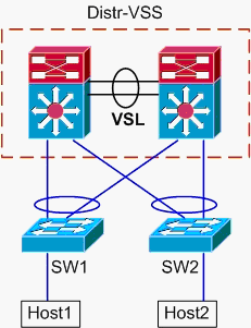
Topology information:
-
Host1 IP/MASK - 10.0.1.15/24
-
Host1 MAC – 0001.0001.0001
-
Host1 Default Gateway – 10.0.1.1 – On Distr-VSS
-
Host2 IP 10.0.2.30
-
Both SW1 and SW2 are Catalyst 6500’s switches operating at Layer 2 only, with etherchannel trunks facing Distr-VSS
-
Trace path from Host1 to VSS Distribution.
Because Host2 is in a different VLAN than Host1, as determined by Host1’s subnet mask, the packet must go to the VSS distribution for routing. In order to find the path of the packet between Host1 and the VSS distribution, it is necessary to first determine the MAC address of Host1’s default gateway. On most operating systems, opening a command prompt and issuing arp –a shows the IP > MAC mapping for the default gateway. When this command was issued on Host1, the MAC returned for 10.0.1.1 was 000a.000a.000a. This MAC can now be looked up in SW1’s MAC-address table.
SW1#show mac-address-table address 000a.000a.000a

Legend: * - primary entry
        age - seconds since last seen
        n/a - not available

  vlan   mac address     type    learn     age              ports
------+----------------+--------+-----+----------+--------------------------
Supervisor:
*    10  000a.000a.000a   dynamic  Yes          0   Po1
This output shows that the MAC-address corresponding to Host1’s default gateway is learned via Port-channel1. What this output does not show, however, is which link in the etherchannel is selected for a particular packet. In order to determine this, the etherchannel load-balancing algorithm must first be checked.
SW1#show etherchannel load-balance
EtherChannel Load-Balancing Configuration:
        src-dst-ip
        mpls label-ip

EtherChannel Load-Balancing Addresses Used Per-Protocol:
Non-IP: Source XOR Destination MAC address
  IPv4: Source XOR Destination IP address
  IPv6: Source XOR Destination IP address
  MPLS: Label or IP
This output shows that the algorithm for IPv4 packets is src-dst-ip. Next, input the relevant flow information into the hash-result command.
SW1#show etherchannel load-balance hash-result interface port-channel
1  ip  10.1.1.1 10.0.2.30

Computed RBH: 0x1
Would select Gig3/2 of Po1
Now that the physical egress point is known, the CDP table can show which physical switch in the VSS this maps to.
SW1#show cdp neighbor Capability Codes: R - Router, T - Trans Bridge, B - Source Route Bridge S - Switch, H - Host, I - IGMP, r - Repeater, P - Phone Device ID Local Intrfce Holdtme Capability Platform Port ID VSS Gig 3/2 157 R S I WS-C6509-EGig 2/1/1 VSS Gig 3/1 128 R S I WS-C6509-EGig 1/1/1 -
Trace Path Through VSS Distribution.
First, check the routing table to determine where Host2 resides.
VSS#show ip route 10.0.2.30

Routing entry for 10.0.2.0/24
  Known via "connected", distance 0, metric 0 (connected, via interface)
  Routing Descriptor Blocks:
  * directly connected, via Vlan20
      Route metric is 0, traffic share count is 1
This previous output shows that Host2 is Layer 3 adjacent to the VSS in Vlan20. In order to find the physical device to Host2, look at the ARP table to find its MAC address.
VSS#show ip arp
Protocol  Address          Age (min)  Hardware Addr   Type   Interface
Internet  10.0.2.1                15   0002.0002.0002  ARPA   Vlan20
Next, take Host2’s MAC address from this output, and use it to find the egress interface in the MAC-address table.
VSS#show mac-address-table address 0002.0002.0002

Legend: * - primary entry
        age - seconds since last seen
        n/a - not available

  vlan   mac address     type    learn     age              ports
------+----------------+--------+-----+----------+--------------------------
    20  0002.0002.0002   dynamic  Yes        210   Po2
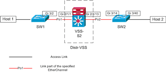
Recall from the earlier CDP output that the packets for this flow entered the VSS on Gig2/1/1, which corresponds to switch 2, module 1, port 1. Again, use the hash-result command to determine physical point of exit from the VSS:
VSS#show etherchannel load-balance
EtherChannel Load-Balancing Configuration:
        src-dst-mixed-ip-port enhanced
        mpls label-ip

EtherChannel Load-Balancing Addresses Used Per-Protocol:
Non-IP: Source XOR Destination MAC address
  IPv4: Source XOR Destination IP address
  IPv6: Source XOR Destination IP address
  MPLS: Label or IP

VSS#show etherchannel load-balance hash-result interface port-channel
2 switch 2 ip 10.0.1.15 vlan 10 10.0.2.30


Computed RBH: 0x6
Would select Gi2/1/13 of Po2
Now, use the CDP table to find information about the downstream switch towards Host2.
VSS#show cdp nei Capability Codes: R - Router, T - Trans Bridge, B - Source Route Bridge S - Switch, H - Host, I - IGMP, r - Repeater, P - Phone, D - Remote, C - CVTA, M - Two-port Mac Relay Device ID Local Intrfce Holdtme Capability Platform Port ID SW2 Gig 2/1/13 129 R S I WS-C6503- Gig 3/14 SW2 Gig 1/1/13 129 R S I WS-C6503- Gig 3/13 -
Trace Path to Host2.
Last, login to SW2 and determine the exact port Host2 is connected to, again using the MAC-address table.
SW2#show mac-address-table address 0002.0002.0002

Legend: * - primary entry
        age - seconds since last seen
        n/a - not available

  vlan   mac address     type    learn     age              ports
------+----------------+--------+-----+----------+--------------------------
    20  0002.0002.0002   dynamic  Yes        140   Gi3/40
Packet Flow Diagram
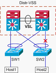
Scenario 2 - Packet Flow between Two Access-Layer Hosts with Layer2 MEC – Broken Redundancy
-
Trace path from Host1 to VSS Distribution.
Procedure is same as Step1 of Scenario1.
-
Trace Path Through VSS Distribution.
This scenario is identical to scenario 1, except the link between Distr-VSS switch 2 and SW2 is broken. Because of this, no active link in port-channel2 exists on switch 2, where the packet from Host1 enters the VSS. Thus, the packet must cross the VSL and egress switch 1. This hash-result output shows this:
VSS#show etherchannel load-balance hash-result interface port-channel 2
switch 2 ip 10.0.1.15 vlan 10 10.0.2.30

Computed RBH: 0x6
Would select Gi1/1/13 of Po2
The hash-result command can also be used to determine which VSL link is chosen to send the frame. In this case, Port-channel10 is the VSL on switch 1, and Port-channel20 is the switch 2 VSL.
VSS#show etherchannel load-balance hash-result int port-channel 20
switch 2 ip 10.0.1.15 vlan  10 10.0.2.30

Computed RBH: 0x6
Would select Te2/5/4 of Po20
Now, use the CDP table to find information about the downstream switch towards Host2.
VSS#show cdp nei Capability Codes: R - Router, T - Trans Bridge, B - Source Route Bridge S - Switch, H - Host, I - IGMP, r - Repeater, P - Phone, D - Remote, C - CVTA, M - Two-port Mac Relay Device ID Local Intrfce Holdtme Capability Platform Port ID SW2 Gig 2/1/13 129 R S I WS-C6503- Gig 3/14 SW2 Gig 1/1/13 129 R S I WS-C6503- Gig 3/13 -
Trace Path to Host2.
Last, login to SW2 and determine the exact port Host2 is connected to, again using the MAC-address table.
SW2#show mac-address-table address 0002.0002.0002

Legend: * - primary entry
        age - seconds since last seen
        n/a - not available

  vlan   mac address     type    learn     age              ports
------+----------------+--------+-----+----------+--------------------------
    20  0002.0002.0002   dynamic  Yes        140   Gi3/40
Packet Flow Diagram
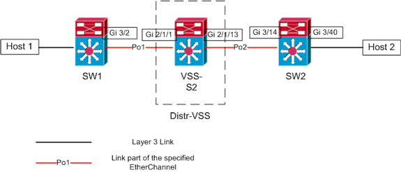
Scenario 3 - Packet Flow between Two Access-Layer Hosts with Layer3 MEC
Topology Information
-
Host1 IP/MASK - 10.0.1.15/24
-
Host1 MAC – 0001.0001.0001
-
Host1 Default Gateway – 10.0.1.1 – On SW1
-
Host2 IP 10.0.2.30
-
Both SW1 and SW2 are Catalyst 6500’s switches operating at Layer 3, with routed etherchannels facing Distr-VSS
-
Trace path from Host1 to VSS Distribution.
Since Host1 is terminated at Layer 3 by SW1, the first step is to look at SW1’s routing table to determine where Host2 resides.
SW1#show ip route 10.0.2.30

Routing entry for 10.0.2.0/24
  Known via "static", distance 1, metric 0
  Routing Descriptor Blocks:
  * 10.100.1.1
      Route metric is 0, traffic share count is 1

SW1#show ip route 10.100.1.1

Routing entry for 10.100.1.0/24
  Known via "connected", distance 0, metric 0 (connected, via interface)
  Routing Descriptor Blocks:
  * directly connected, via Port-Channel1
      Route metric is 0, traffic share count is 1

SW1#sh etherchannel 1 summary
Flags:  D - down        P - bundled in port-channel
        I - stand-alone s - suspended
        H - Hot-standby (LACP only)
        R - Layer3      S - Layer2
        U - in use      N - not in use, no aggregation
        f - failed to allocate aggregator

        M - not in use, no aggregation due to minimum links not met
        m - not in use, port not aggregated due to minimum links not met
        u - unsuitable for bundling
        d - default port

        w - waiting to be aggregated
Number of channel-groups in use: 4
Number of aggregators:           4

Group  Port-channel  Protocol    Ports
------+-------------+-----------+-----------------------------------------------
1      Po1(RU)         LACP      Gi3/1(P)       Gi3/2(P)
Last applied Hash Distribution Algorithm:   -

SW1#show cdp neighbor
Capability Codes: R - Router, T - Trans Bridge, B - Source Route Bridge
                  S - Switch, H - Host, I - IGMP, r - Repeater, P - Phone

Device ID        Local Intrfce     Holdtme    Capability  Platform  Port ID
VSS              Gig 3/2            126         R S I     WS-C6509-EGig 2/1/1
VSS              Gig 3/1            128         R S I     WS-C6509-EGig 1/1/1
The above output shows a single route to the destination via 10.100.1.1, which corresponds to Port-channel1. The show etherchannel command output shows Port-channel1 is comprised of Gig3/1 and Gig3/2, and the CDP table shows both connect to the VSS, with one link per physical switch. Next, the etherchannel hash-result command must be used to determine the exact point of egress from Host1 to Host2.
SW1#show etherchannel load-balance
EtherChannel Load-Balancing Configuration:
        src-dst-ip
        mpls label-ip

EtherChannel Load-Balancing Addresses Used Per-Protocol:
Non-IP: Source XOR Destination MAC address
  IPv4: Source XOR Destination IP address
  IPv6: Source XOR Destination IP address
  MPLS: Label or IP
This output shows that the algorithm for IPv4 packets is src-dst-ip. Next, input the relevant flow information into the hash-result CLI:
SW1#show etherchannel load-balance hash-result interface port-channel 1 ip 10.1.1.1 10.0.2.30

Computed RBH: 0x1
Would select Gig3/2 of Po1
Now it is clear that the flow will leave SW1 via Gi3/2, and enter the VSS on Gig2/1/1, which exists on switch 1.
-
Trace Path Through VSS Distribution.
Next, the routing table entries on the VSS must be checked.
VSS#show ip route 10.0.2.30

Routing entry for 10.0.2.0/24
  Known via "static", distance 1, metric 0
  Routing Descriptor Blocks:
  * 10.200.1.2
      Route metric is 0, traffic share count is 1

VSS#show ip route 10.200.1.2

Routing entry for 10.200.1.0/24
  Known via "connected", distance 0, metric 0 (connected, via interface)
  Routing Descriptor Blocks:
  * directly connected, via Port-channel2
      Route metric is 0, traffic share count is 1
Recall from the earlier CDP output that the packets for this flow entered the VSS on Gig2/1/1, which corresponds to switch 2, module 1, port 1. Again, use the hash-result command to determine physical point of exit from the VSS, making sure to first look up the internal VLAN for Po1:
VSS#show etherchannel load-balance
EtherChannel Load-Balancing Configuration:
        src-dst-mixed-ip-port enhanced
        mpls label-ip

EtherChannel Load-Balancing Addresses Used Per-Protocol:
Non-IP: Source XOR Destination MAC address
  IPv4: Source XOR Destination IP address
  IPv6: Source XOR Destination IP address
  MPLS: Label or IP

VSS#show vlan internal usage | include Port-channel 1

1026 Port-channel 1

VSS#show etherchannel load-balance hash-result interface port-channel 2 switch 2 ip 10.0.1.15 vlan 1026 10.0.2.30

Computed RBH: 0x6
Would select Gi2/1/13 of Po2
Now, use the CDP table to find information about the downstream switch towards Host2.
VSS#show cdp nei
Capability Codes: R - Router, T - Trans Bridge, B - Source Route Bridge
                  S - Switch, H - Host, I - IGMP, r - Repeater, P - Phone,
                  D - Remote, C - CVTA, M - Two-port Mac Relay

Device ID        Local Intrfce     Holdtme    Capability  Platform  Port ID
SW2              Gig 2/1/13        129             R S I  WS-C6503- Gig 3/14
SW2              Gig 1/1/13        129             R S I  WS-C6503- Gig 3/13
This information shows that the packets will egress the VSS via Gig2/1/13, and ingress SW2 on Gig3/14 per the earlier CDP output.
-
Trace Path to Host2.
Last, login to SW2 and determine the exact port Host2 is connected to, again using the MAC-address table.
SW2#show mac-address-table address 0002.0002.0002

Legend: * - primary entry
        age - seconds since last seen
        n/a - not available

  vlan   mac address     type    learn     age              ports
------+----------------+--------+-----+----------+--------------------------
    20  0002.0002.0002   dynamic  Yes        140   Gi3/40
Packet Flow Diagram
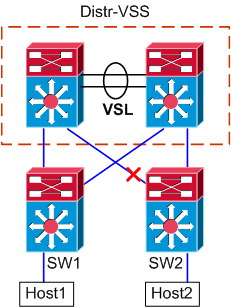
Scenario 4 - Packet Flow between Two Access-Layer Hosts with Layer3 MEC – Broken Redundancy
-
Trace path from Host1 to VSS Distribution.
Procedure is same as Step1 of Scenario 3.
-
Trace Path Through VSS Distribution.
This scenario is identical to scenario 3, except the link between Distr-VSS switch 2 and SW2 is broken. Because of this, no active link in port-channel2 exists on switch 2, where the packet from Host1 enters the VSS, and thus the packet must cross the VSL and egress switch 1. The hash-result output below shows this.
VSS#show etherchannel load-balance hash-result interface port-channel 2 switch 2 ip 10.0.1.15 vlan 1026 10.0.2.30

Computed RBH: 0x6
Would select Gi1/1/13 of Po2
The hash-result command can also be used to determine which VSL link is chosen to send the frame. In this case, Port-channel10 is the VSL on switch 1, and Port-channel20 is the switch 2 VSL.
VSS#show etherchannel load-balance hash-result int port-channel 20 switch 2 ip 10.0.1.15 vlan 1026 10.0.2.30

Computed RBH: 0x6
Would select Te2/5/4 of Po20
-
Trace Path to Host2.
Last, login to SW2 and determine the exact port Host2 is connected to, again using the MAC-address table.
SW2#show mac-address-table address 0002.0002.0002

Legend: * - primary entry
        age - seconds since last seen
        n/a - not available

  vlan   mac address     type    learn     age              ports
------+----------------+--------+-----+----------+--------------------------
    20  0002.0002.0002   dynamic  Yes        140   Gi3/40
Packet Flow Diagram
Scenario 5 - Packet Flow between Two Access-Layer Hosts with ECMP
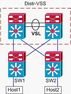
Topology Information
-
Host1 IP/MASK - 10.0.1.15/24
-
Host1 MAC – 0001.0001.0001
-
Host1 Default Gateway – 10.0.1.1 – On SW1
-
Host2 IP 10.0.2.30
-
In the Catalyst 6500, both SW1 and SW2 are terminating attached subnets at Layer 3, with routed links facing Distr-VSS
-
Trace path from Host1 to VSS Distribution.
Because Host1 is terminated at Layer 3 by SW1, the first step is to look at the SW1 routing table to determine where Host2 resides.
SW1#show ip route 10.0.2.30

Routing entry for 10.0.2.0/24
  Known via "static", distance 1, metric 0
  Routing Descriptor Blocks:
  * 10.100.1.1
      Route metric is 0, traffic share count is 1
    10.100.2.1
      Route metric is 0, traffic share count is 1

SW1#show ip route 10.100.1.1

Routing entry for 10.100.1.0/24
  Known via "connected", distance 0, metric 0 (connected, via interface)
  Routing Descriptor Blocks:
  * directly connected, via GigabitEthernet3/1
      Route metric is 0, traffic share count is 1

SW1#show ip route 10.100.2.1

Routing entry for 10.100.2.0/24
  Known via "connected", distance 0, metric 0 (connected, via interface)
  Routing Descriptor Blocks:
  * directly connected, via GigabitEthernet3/2
      Route metric is 0, traffic share count is 1

SW1#show cdp neighbor
Capability Codes: R - Router, T - Trans Bridge, B - Source Route Bridge
                  S - Switch, H - Host, I - IGMP, r - Repeater, P - Phone

Device ID        Local Intrfce     Holdtme    Capability  Platform  Port ID
VSS              Gig 3/2            126         R S I     WS-C6509-EGig 2/1/1
VSS              Gig 3/1            128         R S I     WS-C6509-EGig 1/1/1
The previous output shows equal-cost routes via 10.100.1.1 and 10.100.2.1, which connect via Gig3/1 and Gig3/2, respectively. The CDP table shows both Gig3/1 and Gig3/2 connect to the VSS, with one link per physical switch. Next, the exact-route command must be used to determine the exact point of egress from Host1 to Host2.
SW1#show mls cef exact-route 10.0.1.15 10.0.2.30

Interface: Gi3/1, Next Hop: 10.100.1.1, Vlan: 1030, Destination Mac: 000a.000a.000a
Now it is clear that the flow will leave SW1 via Gi3/1, and enter the VSS on Gig1/1/1, which exists on switch 1.
-
Trace Path Through VSS Distribution.
Next, the routing table entries on the VSS must be checked.
VSS#show ip route 10.0.2.30

Routing entry for 10.0.2.0/24
  Known via "static", distance 1, metric 0
  Routing Descriptor Blocks:
    10.200.2.2
      Route metric is 0, traffic share count is 1
  * 10.200.1.2
      Route metric is 0, traffic share count is 1

VSS#show ip route 10.200.2.2

Routing entry for 10.200.2.0/24
  Known via "connected", distance 0, metric 0 (connected, via interface)
  Routing Descriptor Blocks:
  * directly connected, via GigabitEthernet2/1/13
      Route metric is 0, traffic share count is 1

VSS#show ip route 10.200.1.2

Routing entry for 10.200.1.0/24
  Known via "connected", distance 0, metric 0 (connected, via interface)
  Routing Descriptor Blocks:
  * directly connected, via GigabitEthernet1/1/13
      Route metric is 0, traffic share count is 1

VSS#show cdp nei
Capability Codes: R - Router, T - Trans Bridge, B - Source Route Bridge
                  S - Switch, H - Host, I - IGMP, r - Repeater, P - Phone,
                  D - Remote, C - CVTA, M - Two-port Mac Relay

Device ID        Local Intrfce     Holdtme    Capability  Platform  Port ID
SW2              Gig 1/1/13        121             R S I  WS-C6503- Gig 3/13
SW2              Gig 2/1/13        121             R S I  WS-C6503- Gig 3/14
Here, again equal-cost paths exist for the destination, with one egress point per switch. Since it was earlier determined the packets enter the VSS on switch 1, the next step is to issue the exact-route command specifying switch 1.
VSS#show mls cef exact-route 10.0.1.15 10.0.2.30 switch 1

Interface: Gi1/1/13, Next Hop: 10.200.1.2, Vlan: 1095, Destination Mac: 000b.000b.000b
This information shows that the packets will egress the VSS via Gig1/1/13, and ingress SW2 on Gig3/13 per the earlier CDP output.
-
Trace Path to Host2.
Last, login to SW2 and determine the exact port Host2 is connected to, again using the MAC-address table.
SW2#show mac-address-table address 0002.0002.0002

Legend: * - primary entry
        age - seconds since last seen
        n/a - not available

  vlan   mac address     type    learn     age              ports
------+----------------+--------+-----+----------+--------------------------
    20  0002.0002.0002   dynamic  Yes        140   Gi3/40
Packet Flow Diagram
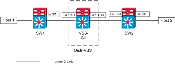
Scenario 6 - Packet Flow between Two Access-Layer Hosts with ECMP – Broken Redundancy
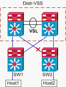
-
Trace path from Host1 to VSS Distribution.
Procedure is same as Step1 of Scenario 5.
-
Trace Path Through VSS Distribution.
The hash-result command can again be used to determine which VSL link is chosen to send the frame. In this case, Port-channel10 is the VSL on switch 1, and Port-channel20 is the switch 2 VSL. The ingress VLAN will be the internal VLAN of Gig1/1/1, the ingress interface.
VSS#show vlan internal usage | include 1/1/1

1026 GigabitEthernet1/1/1

VSS#show etherchannel load-balance hash-result int port-channel 10 switch
1 ip 10.0.1.15 vlan 1026 10.0.2.30

Computed RBH: 0x4
Would select Te1/5/5 of Po10
-
Trace Path to Host2.
Last, login to SW2 and determine the exact port Host2 is connected to, again using the MAC-address table.
SW2#show mac-address-table address 0002.0002.0002

Legend: * - primary entry
        age - seconds since last seen
        n/a - not available

  vlan   mac address     type    learn     age              ports
------+----------------+--------+-----+----------+--------------------------
    20  0002.0002.0002   dynamic  Yes        140   Gi3/40
Packet Flow Diagram
Related Information
- Cisco Catalyst 6500 Virtual Switching System Deployment Best Practices
- Integrate Cisco Service Modules with Cisco Catalyst 6500 Virtual Switching System 1440
- Cisco Catalyst 6500 Virtual Switching System 1440 Product Support
- LAN Product Support
- LAN Switching Technology Support
- Technical Support & Documentation - Cisco Systems
Revision History
| Revision | Publish Date | Comments |
|---|---|---|
1.0 |
02-Apr-2009 |
Initial Release |
Contact Cisco
- Open a Support Case

- (Requires a Cisco Service Contract)
 Feedback