Omni Antenna vs. Directional Antenna
Available Languages
Contents
Introduction
This document gives basic antenna definitions and discusses antenna concepts with a focus on the pros and cons of omni and directional antennas.
Prerequisites
Requirements
There are no specific requirements for this document.
Components Used
This document is not restricted to specific software and hardware versions.
Conventions
Refer to Cisco Technical Tips Conventions for more information on document conventions.
Basic Definitions and Antenna Concepts
An antenna gives the wireless system three fundamental properties: gain, direction and polarization. Gain is a measure of increase in power. Gain is the amount of increase in energy that an antenna adds to a radio frequency (RF) signal. Direction is the shape of the transmission pattern. As the gain of a directional antenna increases, the angle of radiation usually decreases. This provides a greater coverage distance, but with a reduced coverage angle. The coverage area or radiation pattern is measured in degrees. These angles are measured in degrees and are called beamwidths.
An antenna is a passive device which does not offer any added power to the signal. Instead, an antenna simply redirects the energy it receives from the transmitter. The redirection of this energy has the effect of providing more energy in one direction, and less energy in all other directions.
Beamwidths are defined in both horizontal and vertical plains. Beamwidth is the angular separation between the half power points (3dB points) in the radiation pattern of the antenna in any plane. Therefore, for an antenna you have horizontal beamwidth and vertical beamwidth.
Figure 1: Beamwidth of Antenna 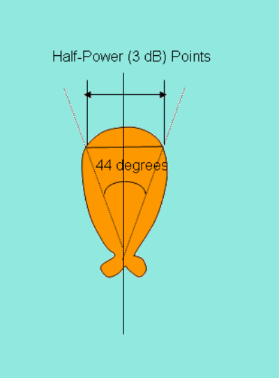
Antennas are rated in comparison to isotropic or dipole antennas. An isotropic antenna is a theoretical antenna with a uniform three-dimensional radiation pattern (similar to a light bulb with no reflector). In other words, a theoretical isotropic antenna has a perfect 360 degree vertical and horizontal beamwidth or a spherical radiation pattern. It is an ideal antenna which radiates in all directions and has a gain of 1 (0 dB), i.e. zero gain and zero loss. It is used to compare the power level of a given antenna to the theoretical isotropic antenna.
Figure 2: Radiation Pattern of an Isotropic Antenna 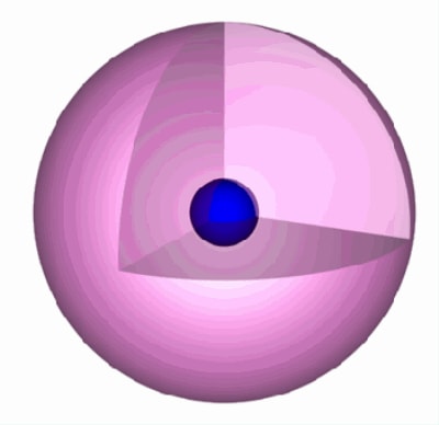
Antennas can be broadly classified as omnidirectional and directional antennas, which depends on the directionality.
Unlike isotropic antennas, dipole antennas are real antennas. The dipole radiation pattern is 360 degrees in the horizontal plane and approximately 75 degrees in the vertical plane (this assumes the dipole antenna is standing vertically) and resembles a donut in shape. Because the beam is slightly concentrated, dipole antennas have a gain over isotropic antennas of 2.14 dB in the horizontal plane. Dipole antennas are said to have a gain of 2.14 dBi, which is in comparison to an isotropic antenna. The higher the gain of the antennas, the smaller the vertical beamwidth is.
Imagine the radiation pattern of an isotropic antenna as a balloon, which extends from the antenna equally in all directions. Now imagine that you press in on the top and bottom of the balloon. This causes the balloon to expand in an outward direction, which covers more area in the horizontal pattern, but reduces the coverage area above and below the antenna. This yields a higher gain, as the antenna appears to extend to a larger coverage area.
Figure 3: Radiation Pattern of an Omni Antenna 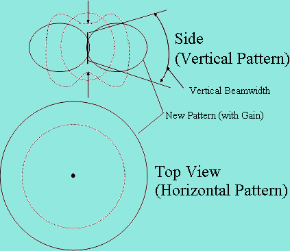
Omnidirectional antennas have a similar radiation pattern. These antennas provide a 360 degree horizontal radiation pattern. These are used when coverage is required in all directions (horizontally) from the antenna with varying degrees of vertical coverage. Polarization is the physical orientation of the element on the antenna that actually emits the RF energy. An omnidirectional antenna, for example, is usually a vertical polarized antenna.
Figure 4: Antenna Polarization 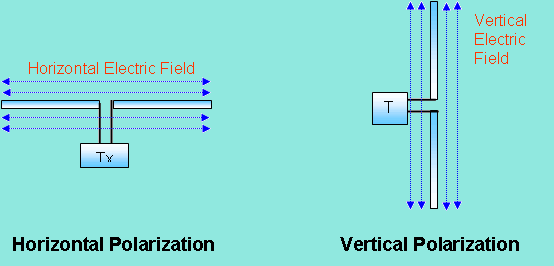
Directional antennas focus the RF energy in a particular direction. As the gain of a directional antenna increases, the coverage distance increases, but the effective coverage angle decreases. For directional antennas, the lobes are pushed in a certain direction and little energy is there on the back side of the antenna.
Figure 5: Radiation Pattern of a Directional Antenna 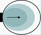
Another important aspect of the antenna is the front-to-back ratio. It measures the directivity of the antenna. It is a ratio of energy which antenna is directing in a particular direction, which depends on its radiation pattern to the energy which is left behind the antenna or wasted. The higher the gain of the antenna, the higher the front-to-back ratio is. A good antenna front-to-back ratio is normally 20 dB.
Figure 6: Typical Radiation Pattern of a Directional Antenna with Calibrated Lobes 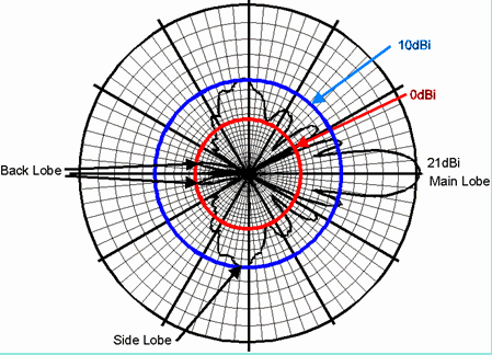
An antenna can have a gain of 21 dBi, a front-to-back ratio of 20 dB or a front-to-side ratio of 15 dB. This means the gain in the backward direction is 1 dBi, and gain off the side is 6 dBi. In order to optimize the overall performance of a wireless LAN, it is important to understand how to maximize radio coverage with the appropriate antenna selection and placement.
Indoor Effects
Wireless propagation can be effected by reflection, refraction or diffraction in a particular environment. Diffraction is the bending of waves around the corners. RF waves can take multipaths between the transmitter and receiver. A multipath is a combination of a primary signal and reflected, refracted or diffracted signal. So on the receiver side, the reflected signals combined with the direct signal can corrupt the signal or increase the amplitude of the signal, which depends on the phases of these signals. Because the distance traveled by the direct signal is shorter than the bounced signal, the time differential causes two signals to be received.
These signals are overlapped and combined into a single one. In real life, the time between the first received signal and the last echoed signal is called the delay spread. Delay spread is the parameter used to signify multipath. The delay of the reflected signals is measured in nano seconds. The amount of delay spread depends upon the amount of obstacles or infrastructure present between the transmitter and receiver. Therefore, delay spread has more value for the manufacturing floor due to lot of metallic structure present as compared to the home environment. Overall, multipath limits the data rate or lowers the performance.
Figure 7: Multipath Effects in Indoor Environment 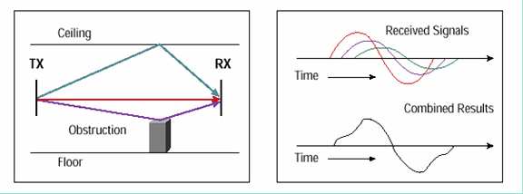
Indoor RF propagation is not the same as it is outdoors. This is due to the presence of solid obstructions, ceilings, and floors that contribute to attenuation and multipath signal losses. Therefore, multipath or delay spread is more in the indoor environment. If the delay spread is more, the interference is more and will cause lower throughput at a particular data rate.
Indoor environment can also be classified as near line of sight (LOS) and non LOS. In near LOS environments, where you can see access points (APs) such as in the hallways, multipath is usually minor and can be overcome easily. The amplitudes of the echoed signals are much smaller than the primary one. However, in non LOS conditions, the echoed signals can have higher power levels, because the primary signal might be partially or totally obstructed, and generally more multipath is present.
Multipath has been a semi-fixed event. However, other factors such as moving objects can enter into play. The particular multipath condition changes from one sample period to the next. This is called time variation.
Multipath interference can cause the RF energy of an antenna to be very high, but the data is unrecoverable. You should not limit the analysis only to the power level. As low RF signal does not mean poor communication, but low signal quality does mean poor communication. You must analyze signal quality and Rx level side by side. High Rx level and low signal quality means there is a lot of interference. You must analyze the channel frequency plan again in such a scenario. Low Rx level and low signal quality means that there is a lot of blockage.
Indoor wave propagation is also affected by the building material. The density of the materials used in the construction of a building determines the number of walls the RF signal can pass through and still maintain adequate coverage. Paper and vinyl walls have little effect on signal penetration. Solid walls, solid floors and pre-cast concrete walls can limit signal penetration to one or two walls without degrading coverage. This can vary widely based any steel reinforcing within the concrete. Concrete and concrete block walls can limit signal penetration to three or four walls. Wood or drywall typically allows for adequate penetration of five or six walls. A thick metal wall causes signals to reflect off, which results in poor penetration. Steel reinforced concrete flooring restricts coverage between floors to perhaps one or two floors.
The higher the frequency, the shorter the wavelength is. Shorter wavelengths have more probability to get absorbed and distorted by a building material. Therefore, 802.11a, which operates in a higher frequency band, is more prone to the building material effect.
The actual effect on the RF must be tested at the site. Therefore, a site survey is necessary. You should do a site survey to see the signal level you receive on the other side of the walls. A change in the type of antenna and location of the antenna can eliminate multipath interference.
Omni Antenna Pros and Cons
Omni antennas are very easy to install. Due to the 360 degrees horizontal pattern, it can even be mounted upside down from a ceiling in the indoor environment. Also, because of its shape it is very convenient to attach these antennas to the product. For example, you might see Rubber Duck antennas attached to the wireless APs. In order to obtain an omnidirectional gain from an isotropic antenna, energy lobes are pushed in from the top and the bottom, and forced out in a doughnut type pattern. If you continue to push in on the ends of the balloon (isotropic antenna pattern), a pancake effect with very narrow vertical beamwidth results, but with a large horizontal coverage. This type of antenna design can deliver very long communications distances, but has one drawback which is poor coverage below the antenna.
Figure 8: Omni Antenna with No Coverage Below the Antenna 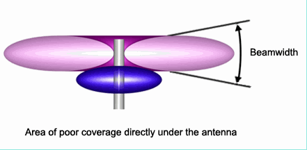
If you try to cover an area from a high point, you see a big hole below the antenna with no coverage.
This problem can be partially solved with the design of something called downtilt. With downtilt, the beamwidths are manipulated to provide more coverage below the antenna than above the antenna. This solution of downtilt is not possible in an omni antenna because of the nature of its radiation pattern.
The omni antenna is usually a vertically polarized antenna, so you cannot have advantages of using cross polarization here to fight interference.
A low gain omni antenna provides a perfect coverage for an indoor environment. It covers more area near the AP or a wireless device in order to increase the probability of receiving the signal in a multipath environment.
Note: In addition to the Cisco Aironet Antennas that work for larger deployments, HGA9N and HGA7S are High-Gain Omnidirectional antennas supported by Cisco for Small Office Environments.
Directional Antenna Pros and Cons
With the directional antennas, you can divert the RF energy in a particular direction to farther distances. Therefore, you can cover long ranges, but the effective beamwidth decreases. This type of antenna is helpful in near LOS coverage, such as covering hallways, long corridors, isle structures with spaces in between, etc. However, as the angular coverage is less, you cannot cover large areas. This is a disadvantage for general indoor coverage because you would like to cover a wider angular area around the AP.
Antenna arrays should face in the direction where the coverage is desired, which can sometimes make mounting a challenge.
Interference
As 802.11 devices operate in the unlicensed bands, this makes it available for anyone to use. WLAN interference comes from other similar devices and other sources such as microwave ovens, cordless phones, radar signals from a nearby airport, etc. Interference is also found from other technologies that use the same band as Bluetooth or security devices. In the 2.4 GHz unlicensed there are limited channels to utilize to avoid interference, with only three non-overlapping channels available.
Interference and multipath cause the receive signal to fluctuate at a particular frequency. This variation of signal is called fading. Fading is also frequency selective, as attenuation varies with frequency. A channel can be classified as either a fast fading channel or slow fading channel. This depends on how rapidly the transmitted base band signal changes. A mobile receiver that travels through an indoor environment can receive rapid signal fluctuations caused by additions and cancellations of the direct signals at half wavelength intervals.
Interference increases the requirement of signal to noise ratio (SNR) for a particular data rate. The packet retry count goes up in an area where interference or multipath is very high. A change in the type of antenna and location of the antenna can eliminate multipath interference. Antenna gain adds to the system gain and improves signal and interference to noise ration (SINR) requirements as shown here:
Figure 9: Noise Floor and Signal and Interference to Noise Ratio 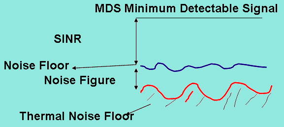
Although directional antennas help to focus the energy in a particular direction which can help to overcome fading and multipath, multipath itself reduces the focusing power of a directional antenna. The amount of multipath seen by a user at a long distance from the AP can be much more.
Directional antennas used for the indoors typically have a lower gain, and as a result, have a lower front-to-back and front-to-side lobe ratios. This results in less ability to reject or reduce the interference signals received from directions outside the primary lobe area.
Conclusion
While directional antennas can be of great value for certain indoor applications, the vast majority of indoor installations utilize omnidirectional antennas for the reasons cited in this document. The selections of an antenna, directional or omnidirectional, should be strictly determined by a correct and proper site survey.
Related Information
- Cisco Aironet Antennas and Accessories Reference Guide
- Antenna Cabling
- WLAN Radio Coverage Area Extension Methods
- Wireless Site Survey FAQ
- Troubleshooting Connectivity in a Wireless LAN Network
- Multipath and Diversity
- Outdoor Bridge Range Calculation Utility
- Troubleshooting Problems Affecting Radio Frequency Communication
- Technical Support & Documentation - Cisco Systems
Contact Cisco
- Open a Support Case

- (Requires a Cisco Service Contract)
 Feedback