Cisco CRS Carrier Routing System Ethernet Physical Layer Interface Module Installation Note
This document describes the various Ethernet physical layer interface modules (PLIMs) used in the Cisco CRS-1 Carrier Routing System 16-slot, 8-slot, and 4-slot line card chassis (LCC). It provides an overview of the different Ethernet PLIMs and provides instructions on how to remove and install a PLIM and its associated components.
Changes to This Document
The following table lists the technical changes made to this document since it was first printed.
|
Date |
Change Summary |
|---|---|
|
July 2018 |
Added information about the CPAK-100G-CWDM4 optics that is supported on 4-Port 100-GE CPAK PLIM and the 2-port 100-GE/5-port 40-GE QSFP+ Combination PLIM . |
|
September 2015 |
Added information about the supported SR-4 breakout cable for 2-port 100-GE and 5-port 40-GE QSFP+ Combination PLIM. |
|
July 2014 |
Added information about the new 2-port 100-GE and 5-port 40-GE QSFP+ combination PLIM. Also added section about the QSFP+ modules. |
|
January 2014 |
Added information about the new 40-port 10-GE SFP+ PLIM and the new 4-port 100-GE CPAK PLIM. Also added sections about the SFP+ and CPAK modules. |
|
June 2013 |
Added information about replacing an SFP on a line card that uses an articulated bracket. |
|
September 2012 |
Added information about the new 1-port 100-GE IPoDWDM PLIM and the new 2-port and 4-port 40-GE OTU3 CFP PLIMs. |
|
May 2012 |
Added information about the CFP-100G-SR10 optical module on the Cisco CRS-3 Series Router platform. This CFP-100G-SR10 optical module enables connection to the Cisco CRS-3 Series Router 1-port 100-GE PLIM using multimode fiber rather than only single mode fiber. |
|
February 2012 |
Added information about the articulated cable bracket for the 20-port 1-GE FLEX PLIM and the 42-port 1-GE XFP PLIM to the Removing a PLIM Cable Management Bracket section and the Installing a PLIM Cable Management Bracket section. |
|
June 2011 |
Added information about XFP power budgeting for the 20-port and 14-port 10-GE XFP PLIMs. Added information about additional 10-GE and DWDM XFP modules supported on the 20-port, 14-port, 8-port, and 4-port 10-GE XFP PLIMS. |
|
November 2010 |
Added information about SPAs supported by the 20-port 1-GE FLEX PLIM and the 2-port 10-GE FLEX PLIM. |
|
October 2010 |
Added information about new 20-port and 14-port 10-GE XFP PLIMs. |
|
April 2010 |
Added information about new 8-port and 4-port 10-GE XFP PLIMs, and added optics information about XFP modules for the new PLIMs. |
|
July 2009 |
Corrections were made to the 4-port 10-GE PLIM, 42-port 1-GE PLIM, 20-port 1-GE FLEX PLIM, and 2-port 10-GE FLEX PLIM. |
|
February 2007 |
Added information about the extended-wavelength GE optics module to the Ethernet PLIMs section and About PLIM Impedance Carriers section. |
|
July 2006 |
|
|
March 2006 |
|
|
November 2004 |
Initial release of the document. |
Important Information
This section contains the following sections:
Product Numbers
The following table lists the Cisco product numbers for the products to which this publication applies.
|
Name |
Product Number |
Description |
Minimum Cisco IOS XR Release |
Hardware Revision Number |
||
|---|---|---|---|---|---|---|
|
2x100-G and 5-x40-GE QSFP+ combination PLIM |
2X100GE-FLEX-40= |
Cisco CRS 2-port 100-GE and 5-port 40-GE QSFP+ combination PLIM |
5.1.3 |
— |
||
|
4x100-GE CPAK PLIM |
4x100GE-LO= |
Cisco CRS 4-port 100-GE LAN/OTN CPAK PLIM |
5.1.1 |
— |
||
|
40x10-GE SFP+ PLIM |
40x10GE-WLO= |
Cisco CRS 40-port 10-GE WAN/LAN/OTN SFP+ PLIM |
5.1.1 |
— |
||
|
1x100-GE IPoDWDM PLIM |
1-100GE-DWDM/C |
Cisco CRS 1-port 100-GE IP over DWDM PLIM |
4.2.3 |
— |
||
|
2x40-GE OTU3 CFP PLIM |
2-40GE-L/OTN |
Cisco CRS 2-port 40-GE CFP PLIM |
4.2.3 |
— |
||
|
4x40-GE OTU3 CFP PLIM |
4-40GE-L/OTN |
Cisco CRS 4-port 40-GE CFP PLIM |
4.2.3 |
— |
||
|
1x100-GE CFP PLIM |
1X100GBE |
Cisco CRS 1-port 100-GE CFP PLIM |
4.0.0 |
— |
||
|
20x10-GE XFP PLIM |
20X10GBE-WL-XFP |
Cisco CRS 20-port 10-GE WAN/LAN XFP PLIM |
4.0.0 |
— |
||
|
14x10-GE XFP PLIM |
14X10GBE-WL-XFP |
Cisco CRS 14-port 10-GE WAN/LAN XFP PLIM |
4.0.0 |
— |
||
|
8x10-GE XFP PLIM |
8-10GBE-WL-XFP |
Cisco CRS-1 8-port 10-GE WAN/LAN XFP PLIM |
3.8.4 |
— |
||
|
4x10-GE XFP PLIM |
4-10GBE-WL-XFP |
Cisco CRS-1 4-port 10-GE WAN/LAN XFP PLIM |
3.8.4 |
— |
||
|
4x10-GE PLIM |
4-10GE= |
Cisco CRS-1 4-port 10-GE PLIM |
3.8.1 |
— |
||
|
42x1-GE PLIM |
42-1GE= |
Cisco CRS-1 42-port 1-GE PLIM |
3.8.1 |
— |
||
|
20x1-GE-FLEX |
20-1GE-FLEX= |
Cisco CRS-1 20-port 1-GE Flexible Interface Module |
3.8.1 |
— |
||
|
2x10-GE FLEX |
2-10GE-WL-FLEX 2-10GE-WL-FLEX= |
2x10-GE WAN/LAN Flexible Interface Module |
3.8.1 |
— |
||
|
4x10-GE DWDM PLIM |
4-10GE-ITU/C= |
Cisco CRS-1 4-Port 10-GE (C-band) DWDM PLIM |
3.3 |
73-10209-02 A0 |
||
|
8x10-GE XENPAK PLIM |
8-10GBE= |
8-port 10-GE PLIM using XENPAK optics modules:
|
3.0 |
73-9231-08 A0 |
||
|
PLIM impedance carrier |
CRS-INT-IMPEDANCE= |
Blank card carrier for each empty PLIM slot (required for EMI compliance and cooling) |
3.0 |
— |
Router Hardware Installation
For hardware installation and configuration information for the Cisco CRS-1, see the router hardware installation documents in the Related Documentation section. These documents include information on the router switch fabric and how it affects operation of the PLIM. They also include PLIM slot locations and other requirements.
The PLIMs described in this document are supported on the 16-slot, 8-slot, and 4-slot Cisco CRS line card chassis.
Cisco IOS XR Software Release Requirements
The above table lists the Cisco IOS XR releases that are compatible with the CRS PLIMs.
For software configuration information, see the Cisco IOS XR software configuration and command reference publications for the installed Cisco IOS XR release at:
http://www.cisco.com/en/US/products/ps5763/products_installation_and_configuration_guides_list.html
See the Cisco IOS XR software release notes for additional software release information at:
http://www.cisco.com/en/US/products/ps5763/prod_release_notes_list.html
Hardware Revision Requirements
To ensure compatibility with the software, your Ethernet PLIM should have a specific hardware revision number. This number is printed on a label affixed to the component side of the PLIM. The hardware revision number can also be displayed using the show diag command. Minimum revision numbers are listed in the above table.
Related Documentation
For complete planning, installation, and configuration information, see the documents for your chassis type (16-slot, 8-slot, or 4-slot) listed in this section. Cisco CRS-1 product documentation is available on line at:
http://www.cisco.com/univercd/cc/td/doc/product/core/crs/index.htm
Hardware Documents
- Cisco CRS Carrier Routing System 16-Slot Line Card Chassis Site Planning Guide
- Cisco CRS Carrier Routing System 8-Slot Line Card Chassis Site Planning Guide
- Cisco CRS Carrier Routing System 4-Slot Line Card Chassis Site Planning Guide
- Cisco CRS Carrier Routing System 16-Slot Line Card Chassis System Description
- Cisco CRS Carrier Routing System 8-Slot Line Card Chassis System Description
- Cisco CRS Carrier Routing System 4-Slot Line Card Chassis System Description
- Cisco CRS Carrier Routing System 16-Slot Line Card Chassis Unpacking, Moving, and Securing Guide (attached to the crate)
- Cisco CRS Carrier Routing System 8-Slot Line Card Chassis Unpacking, Moving, and Securing Guide (attached to the crate)
- Cisco CRS Carrier Routing System 4-Slot Line Card Chassis Unpacking, Moving, and Securing Guide (attached to the crate)
- Cisco CRS Carrier Routing System 16-Slot Line Card Chassis Installation Guide
- Cisco CRS Carrier Routing System 8-Slot Line Card Chassis Installation Guide
- Cisco CRS Carrier Routing System 4-Slot Line Card Chassis Installation Guide
- Regulatory Compliance and Safety Information for the Cisco CRS-1 Carrier Routing System (ships with the product)
Software Documents
For a complete listing of software documentation available for the Cisco CRS-1, see About Cisco IOS XR Software Documentation for your release, available on line at:
http://www.cisco.com/en/US/products/ps5763/products_documentation_roadmaps_list.html
About Physical Layer Interface Modules
A physical layer interface module (PLIM) provides the packet interfaces for the routing system. Optics modules on the PLIM contain ports to which fiber-optic cables are connected. User data is received and transmitted through the PLIM ports and converted between the optical signals (used in the network) and the electrical signals (used by Cisco CRS-1 components).
Each PLIM is paired with a modular services card (MSC) through the chassis midplane. The MSC provides Layer 3 services for the user data, and the PLIM provides Layer 1 and Layer 2 services. An MSC can be paired with different PLIMs to provide a variety of packet interfaces and port densities (for example, OC-192c/STM-64c POS and 10-GE).
MSCs and PLIMs are installed on opposite sides of the line card chassis and mate through the chassis midplane. Each MSC and PLIM pair is installed in corresponding chassis slots in the chassis (on opposite sides of the chassis). The chassis midplane enables you to remove and replace an MSC without disconnecting the user cables on the PLIM.
The Cisco CRS-1 supports the following number of PLIMs for each chassis type. You can mix and match PLIM types in the chassis.
- The 16-slot chassis supports from 1 to 16 PLIMs.
- The 8-slot chassis supports from 1 to 8 PLIMs.
- The 4-slot chassis supports from 1 to 4 PLIMs.
For additional information about the operation of MSCs and PLIMs, see Cisco CRS-1 Carrier Routing System Line Card Chassis System Description for the 16-slot, 8-slot, or 4-slot chassis.
Ethernet PLIMs
Ethernet PLIMs provide data packet buffering, Layer 2 processing, and multiplexing and demultiplexing of the GE data streams, including processing for VLANs and back-pressure signals from the MSC. In addition, PLIMs include power and clocking components, voltage and temperature sensors, and an identification EEPROM that stores initial configuration and PLIM hardware information.
The Ethernet PLIMs all share the following features:
- ARPA, IEEE 802.2/SAP, and IEEE 802.3/SNAP encapsulation
- IEEE 802.x flow control
- IEEE 802.1q VLAN support (with jumbo frames)
- IEEE 802.1p tagging
- Source and destination MAC and VLAN accounting
- Online insertion and removal (OIR)
- Cisco IOS XR CLI, S1008P, XML, and Craft Works Interface (CWI) network management tools
- Compliance with network and industry standards
For additional features and specifications, see the data sheets at:
http://www.cisco.com/en/US/products/ps5763/products_data_sheets_list.html
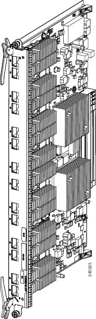
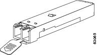
The following figure shows a typical PLIM. The 14-port 10-GE XFP PLIM is shown; other PLIMs are similar.
The following sections provide information specific to the Ethernet PLIMs currently available for the Cisco CRS-1:
1-GE PLIMs
This section provides information specific to the following 1-GE PLIMs:
The following sections provide information about SFP optics modules:
20-Port 1-GE Flex PLIM with SFP Optics Modules
The 20-port 1-GE Flex PLIM supports from one to twenty pluggable SFP optics modules.
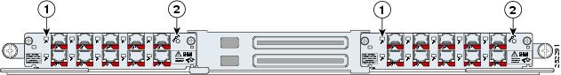
Ports and LEDs
The 20-port 1-GE Flex PLIM has the following LEDs:
- Status LED for the PLIM
- Port LEDs that indicate the port status
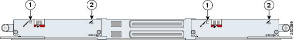
|
1 |
Port LEDs |
2 |
Status LED |
The following table describes the PLIM LEDs for the 20-Port 1-GE Flex PLIM.
|
LED |
State |
Description |
|---|---|---|
|
Status |
Green |
PLIM is properly seated and operating correctly. |
|
Yellow |
PLIM has a problem. |
|
|
Off |
PLIM is not properly seated or system power is off. |
|
|
Port |
On |
Port is logically active and the laser is on. |
|
Off |
Port is not active. |
Physical Characteristics
- Height—20.6 in. (52.3 cm)
- Depth—11.2 in. (28.5 cm)
- Width—1.8 in. (4.6 cm)
- Weight—8.6 lb (3.9 kg)
- Power consumption—150 W
The 20-Port 1-GE Flex PLIM has twenty electrical connectors that support SFP modules. Each port can send and receive traffic using cabling appropriate for the SFP module inserted.
20-Port 1-GE Flex PLIM SPA Support
The 20-Port 1-GE Flex PLIM provides 20 ports of IEEE 802.3-compliant GE interfaces and two available Cisco I-Flex shared port adapter (SPA) slots. These slots can support up to up to 2 additional half-height SPAs.
The SPAs supported in the two available Cisco I-Flex shared port adapter (SPA) slots can be Packet over SONET/SDH (PoS) or Ethernet. The following SPAs are supported:
- SPA-5X1GE-V2
- SPA-8X1GE
- SPA-8X1GE-V2
- SPA-10X1GE-V2
- SPA-1X10GE-L-V2
- SPA-1X10GE-WL-V2
- SPA-4XOC3-POS
- SPA-8XOC12-POS
- SPA-2XOC48POS/RPR
- SPA-4XOC48POS/RPR
- SPA-OC192POS-VSR
- SPA-OC192POS-XFP
Refer to the Installing and Removing a Shared Port Adapter chapter of the Cisco CRS-1 SIP and SPA Hardware Installation Guide online here: http://www.cisco.com/en/US/docs/interfaces_modules/shared_port_adapters/install_upgrade/crs/crs1/installation/guide/crsspain.html for instructions on replacing the SPAs.
Refer to the Overview: Cisco CRS-1 Shared Port Adapters chapter of the Cisco CRS-1 SIP and SPA Hardware Installation Guide online here: http://www.cisco.com/en/US/docs/interfaces_modules/shared_port_adapters/install_upgrade/crs/crs1/installation/guide/crsspaov.html for descriptions of each of the supported SPAs.
42-Port 1-GE PLIM with SFP Optics Modules
- The 42-port 1-GE PLIM supports from one to forty two pluggable SFP optics modules.
Ports and LEDs
The 42-port 1-GE SFP PLIM has the following LEDs:
- Status LED for the PLIM
- Port LEDs that indicate the port status

|
1 |
Port LEDs |
2 |
Status LED |
The following table describes the PLIM LEDs for the 42-Port 1-GE SFP PLIM.
|
LED |
State |
Description |
|---|---|---|
|
Status |
Green |
PLIM is properly seated and operating correctly. |
|
Yellow |
PLIM has a problem. |
|
|
Off |
PLIM is not properly seated or system power is off. |
|
|
Port |
On |
Port is logically active and the laser is on. |
|
Off |
Port is not active. |
Physical Characteristics
- Height—20.6 in. (52.3 cm)
- Depth—11.2 in. (28.5 cm)
- Width—1.8 in. (4.6 cm)
- Weight—8.6 lb (3.9 kg)
- Power consumption—150 W
The interface connectors on the 42-port 1-GE SFP PLIM are eight individual fiber-optic receivers that support SFP modules. Each port can send and receive traffic using the optical fiber connections.
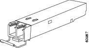
SFP Module Connections
The small form-factor pluggable (SFP) module is an input/output (I/O) device that plugs into the GE optical slots on the 20-Port 1-GE Flex PLIM or the 42-port 1-GE SFP PLIM, linking the port with a 1000BASE-X fiber-optic network.
The 20-Port 1-GE Flex PLIM and 42-port 1-GE SFP PLIM accept only the SFP modules listed as supported in this document. An SFP module check is run every time an SFP is inserted, and only SFP modules that pass this check can be used by the 20-port 1-GE PLIM or the 42-port 1-GE SFP PLIM.
SFP modules exist for technologies other than GE and for products other than the 20-Port 1-GE Flex PLIM and the 42-port 1-GE SFP PLIM. However, the information in this document pertains only to SFP modules that plug into the 20-Port 1-GE Flex PLIM or 42-port 1-GE SFP PLIM ports.
The SFP module has a receiver port (RX) and a transmitter port (TX) that compose one optical interface.
|
SFP Module Product Number |
SFP Module |
Description |
|---|---|---|
|
SFP-GE-S |
Short wavelength (1000BASE-SX) |
Contains a Class 1 laser of 850 nm for 1000BASE-SX (short-wavelength) applications. |
|
SFP-GE-L |
Long wavelength/long haul (1000BASE-LX/LH) |
Contains a Class 1 laser of 1310 nm for 1000BASE-LX/LH (long-wavelength) applications. |
|
SFP-GE-Z |
Extended wavelength (1000BASE-ZX) |
Contains a Class 1 laser of 1550 nm for 1000BASE-ZX (extended-wavelength) applications. |
|
Specification |
Description |
||
|---|---|---|---|
|
Wavelength (nm) |
SFP-GE-S: 770 to 860SFP-GE-L: 1270 to 1355SFP-GE-Z: 1500 to 1580 |
||
|
Cabling distance (maximum) |
SFP-GE-S: 500 m on 50/125 micron MMF; 300 m on 62.5/125 micron MMFSFP-GE-L: 6.2 miles (10 km)SFP-GE-Z: 49.7 miles (80 km)
|
||
|
Operating case temperature range |
SFP-GE-S: 23 to 185 degrees F (–5 to 85 degrees C)SFP-GE-L: 23 to 185 degrees F (–5 to 85 degrees C)SFP-GE-Z: 23 to 185 degrees F (–5 to 85 degrees C) |
||
|
Storage temperature range |
SFP-GE-S: –40 to 185 degrees F (–40 to 85 degrees C)SFP-GE-L: –40 to 185 degrees F (–40 to 85 degrees C)SFP-GE-Z: –40 to 185 degrees F (–40 to 85 degrees C) |
||
|
Supply voltage range |
SFP-GE-S: 3.1 to 3.5 VSFP-GE-L: 3.1 to 3.5 VSFP-GE-Z: 3.1 to 3.5 V |
SFP-GE-S Modules
The 1000BASE-SX (short-wavelength) module operates on standard multimode fiber-optic link spans of up to 500 m on 50/125 micron MMF (multimode fiber) and 300 m on 62.5/125 micron MMF.
SFP-GE-L Modules
The 1000BASE-LX/LH (long-wavelength/long-haul) module interfaces fully comply with theIEEE 802.3z 1000BASE-LX standard. However, their higher optical quality allows them to reach 6.2 miles (10 km) over single-mode fiber (SMF) versus the 3.1 miles (5 km) specified in the standard.
SFP-GE-Z Modules
The 1000BASE-ZX (extended-wavelength) module operates on ordinary single-mode fiber-optic link spans of up to 49.7 miles (80 km). Link spans of up to 62.1 miles (100 km) are possible using premium single-mode fiber or dispersion-shifted single-mode fiber. (Premium single-mode fiber has a lower attenuation per unit length than ordinary single-mode fiber; dispersion-shifted single-mode fiber has both lower attenuation and less dispersion.)
The 1000BASE-ZX module must be coupled to single-mode fiber-optic cable, which is the type of cable typically used in long-haul telecommunications applications. The 1000BASE-ZX module does not operate correctly when coupled to multimode fiber, and it is not intended to be used in environments in which multimode fiber is frequently used (for example, building backbones or horizontal cabling).
The 1000BASE-ZX module is intended to be used as a Physical Medium Dependent (PMD) component for GE interfaces found on various switch and router products. It operates at a signaling rate of 1250 Mbaud, transmitting and receiving 8B/10B encoded data.
When shorter lengths of single-mode fiber are used, it may be necessary to insert an inline optical attenuator in the link to avoid overloading the receiver. Use the following guidelines:
- Insert a 10-dB inline optical attenuator between the fiber-optic cable plant and the receiving port on the 1000BASE-ZX module at each end of the link whenever the fiber-optic cable span is less than 15.5 miles (25 km).
- Insert a 5-dB inline optical attenuator between the fiber-optic cable plant and the receiving port on the 1000BASE-ZX module at each end of the link whenever the fiber-optic cable span is equal to or greater than 15.5 miles (25 km) but less than 31 miles (50 km).
SFP Module Cabling and Connection Equipment
The following table provides cabling specifications for the SFP modules that can be installed on the 20-Port 1-GE Flex PLIM and the 42-port 1-GE SFP PLIM. Note that all SFP ports have LC-type connectors.
The minimum cable distance for the SFP-GE-S is 6.5 feet (2 m), and the minimum link distance for the SFP-GE-Z is 6.2 miles (10 km) with an 8-dB attenuator installed at each end of the link. Without attenuators, the minimum link distance for the SFP-GE-Z is 24.9 miles (40 km).
|
SFP Modules |
Wavelength (nm) |
Fiber Type |
Core Size (micron) |
Modal Bandwidth (MHz/km) |
MaximumCable Distance |
||
|---|---|---|---|---|---|---|---|
|
SFP-GE-S |
850 |
MMF
|
62.5 |
160 |
722 ft (220 m) |
||
|
62.5 |
200 |
984 ft (300 m) |
|||||
|
50.0 |
400 |
1640 ft (500 m) |
|||||
|
50.0 |
500 |
1804 ft (550 m) |
|||||
|
SFP-GE-L |
1300 |
SMF |
9/10 |
— |
6.2 miles (10 km) |
||
|
SFP-GE-Z |
1500 |
SMF |
9/10 |
— |
49.7 miles (80 km) |
||
|
SMF
|
8 |
— |
62.1 miles (100 km) |
|
SFP Modules |
Wavelength (nm) |
Fiber Type |
Core Size (micron) |
Modal Bandwidth (MHz/km) |
MaximumCable Distance |
||
|---|---|---|---|---|---|---|---|
|
SFP-GE-S |
850 |
MMF
|
62.5 |
160 |
722 ft (220 m) |
||
|
62.5 |
200 |
984 ft (300 m) |
|||||
|
50.0 |
400 |
1640 ft (500 m) |
|||||
|
50.0 |
500 |
1804 ft (550 m) |
|||||
|
SFP-GE-L |
1300 |
MMF and SMF 1 |
62.5 |
500 |
1804 ft (550 m) |
||
|
50.0 |
400 |
1804 ft (550 m) |
|||||
|
50.0 |
500 |
1804 ft (550 m) |
|||||
|
9/10 |
— |
6.2 miles (10 km) |
|||||
|
SFP-GE-Z |
1550 |
SMF |
9/10 |
— |
49.7 miles (80 km) |
||
|
SMF
|
8 |
— |
62.1 miles (100 km) |
 Note |
The 1000BASE-ZX SFP modules provide an optical power budget of 21.5 dB. You should measure your cable plant with an optical loss test set to verify that the optical loss of the cable plant (including connectors and splices) is less than or equal to 21.5 dB. The optical loss measurement must be performed with a 1550-nm light source. |
Installing and Removing SFP Modules
Before you remove or install an SFP module, read the installation information in this section and the safety information in the Laser Safety section.
 Caution |
Protect the SFP modules by inserting clean dust covers into them after the cables are removed. Be sure to clean the optic surfaces of the fiber cables before you plug them back into the optical ports of another module. Avoid getting dust and other contaminants into the optical ports of your SFP modules, because the optics do not work correctly when obstructed with dust. |
Caution |
It is strongly recommended that you do not install or remove the SFP module with fiber-optic cables attached to it because of the potential to damage the cable, the cable connector, or the optical interfaces in the module. Disconnect all cables before removing or installing the SFP module.Removing and inserting an module can shorten its useful life, so you should not remove and insert modules any more often than is absolutely necessary. |
SFP modules use one of four different latching devices to install and remove the module from a port. The four types of SFP module latching devices are described in the following sections:
Note |
When installing the SFP module, you should hear a click as the triangular pin on the bottom of the module snaps into the hole in the receptacle, indicating that the module is correctly seated and secured in the receptacle. Verify that the modules are completely seated and secured in their assigned receptacles on the line card by firmly pushing on each SFP module. |
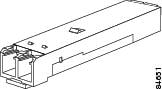
Bail Clasp SFP Module
The bail clasp SFP module has a clasp that you use to remove or install the module (see the following figure).
Installing a Bail Clasp SFP Module
To install this type of SFP module, follow these steps:
SUMMARY STEPS
- Attach an ESD-preventive wrist or ankle strap and follow its instructions for use.
- Close the bail clasp before inserting the SFP module.
- Line up the SFP module with the port and slide it into the port (see the following figure).
DETAILED STEPS
| Step 1 |
Attach an ESD-preventive wrist or ankle strap and follow its instructions for use. |
| Step 2 |
Close the bail clasp before inserting the SFP module. |
| Step 3 |
Line up the SFP module with the port and slide it into the port (see the following figure). 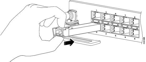 |
What to do next
Note |
When installing an SFP module, you should hear a click as the triangular pin on the bottom of the SFP module snaps into the hole in the receptacle, indicating that the module is correctly seated and secured in the receptacle. Verify that the SFP modules are completely seated and secured in their assigned receptacles on the line card by firmly pushing on each SFP module. |
Removing a Bail Clasp SFP Module
To remove this type of SFP module, follow these steps:
SUMMARY STEPS
- Attach an ESD-preventive wrist or ankle strap and follow its instructions for use.
- Disconnect and remove all interface cables from the ports; note the current connections of the cables to the ports on the line card.
- Open the bail clasp on the SFP module with your index finger in a downward direction, as shown in the following figure. If the bail clasp is obstructed and you cannot use your index finger to open it, use a small flat-blade screwdriver or other long, narrow instrument to open the bail clasp.
- Grasp the SFP module between your thumb and index finger and carefully remove it from the port, as shown in the following figure.
- Place the removed SFP module on an antistatic mat, or immediately place it in a static shielding bag if you plan to return it to the factory.
- Protect your line card by inserting clean SFP module cage covers into the optical module cage when there is no SFP module installed.
DETAILED STEPS
| Step 1 |
Attach an ESD-preventive wrist or ankle strap and follow its instructions for use. |
| Step 2 |
Disconnect and remove all interface cables from the ports; note the current connections of the cables to the ports on the line card. |
| Step 3 |
Open the bail clasp on the SFP module with your index finger in a downward direction, as shown in the following figure. If the bail clasp is obstructed and you cannot use your index finger to open it, use a small flat-blade screwdriver or other long, narrow instrument to open the bail clasp. |
| Step 4 |
Grasp the SFP module between your thumb and index finger and carefully remove it from the port, as shown in the following figure. 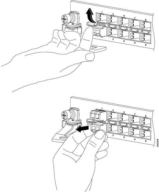 |
| Step 5 |
Place the removed SFP module on an antistatic mat, or immediately place it in a static shielding bag if you plan to return it to the factory. |
| Step 6 |
Protect your line card by inserting clean SFP module cage covers into the optical module cage when there is no SFP module installed. |
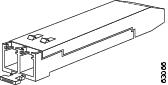
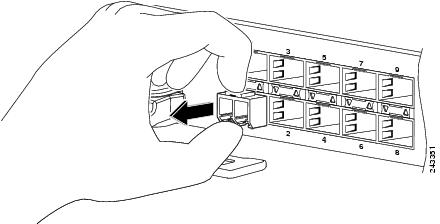
Mylar Tab SFP Module
The mylar tab SFP module has a tab to pull to remove the module from a port (see the following figure).
Installing a Mylar Tab SFP Module
To install this type of SFP module, follow these steps:
SUMMARY STEPS
- Attach an ESD-preventive wrist or ankle strap and follow its instructions for use.
- Line up the SFP module with the port, and slide it into place (see the following figure).
DETAILED STEPS
| Step 1 |
Attach an ESD-preventive wrist or ankle strap and follow its instructions for use. |
| Step 2 |
Line up the SFP module with the port, and slide it into place (see the following figure). 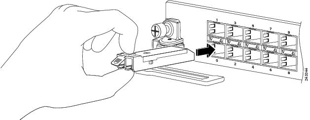 |
What to do next
Note |
When installing an SFP module, you should hear a click as the triangular pin on the bottom of the SFP module snaps into the hole in the receptacle, indicating that the module is correctly seated and secured in the receptacle. Verify that the SFP modules are completely seated and secured in their assigned receptacles on the line card by firmly pushing on each SFP module. |
Removing a Mylar Tab SFP Module
To remove this type of SFP module, follow these steps:
SUMMARY STEPS
- Attach an ESD-preventive wrist or ankle strap and follow its instructions for use.
- Disconnect and remove all interface cables from the ports; note the current connections of the cables to the ports on the line card.
- Pull the tab gently in a slightly downward direction until it disengages from the port, then pull the SFP module out (see the following figure).
- Place the removed SFP module on an antistatic mat, or immediately place it in a static shielding bag if you plan to return it to the factory.
- Protect your line card by inserting clean SFP module cage covers into the optical module cage when there is no SFP module installed.
DETAILED STEPS
| Step 1 |
Attach an ESD-preventive wrist or ankle strap and follow its instructions for use. |
| Step 2 |
Disconnect and remove all interface cables from the ports; note the current connections of the cables to the ports on the line card. |
| Step 3 |
Pull the tab gently in a slightly downward direction until it disengages from the port, then pull the SFP module out (see the following figure). 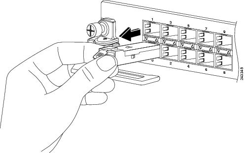 |
| Step 4 |
Place the removed SFP module on an antistatic mat, or immediately place it in a static shielding bag if you plan to return it to the factory. |
| Step 5 |
Protect your line card by inserting clean SFP module cage covers into the optical module cage when there is no SFP module installed. |
What to do next
When pulling the tab to remove the SFP module, be sure to pull in a straight outward motion so you remove the SFP module from the port in a parallel direction. Do not twist or pull the tab, because you might disconnect it from the SFP module.
Actuator Button SFP Module
The actuator button SFP module includes a button that you push in order to remove the SFP module from a port (see the following figure).
Installing an Actuator Button SFP Module
To install this type of SFP module, follow these steps:
SUMMARY STEPS
- Attach an ESD-preventive wrist or ankle strap and follow its instructions for use.
- Line up the SFP module with the port and slide it in until the actuator button clicks into place (see the following figure). Be sure not to press the actuator button as you insert the SFP module because you might inadvertently disengage the SFP module from the port.
DETAILED STEPS
| Step 1 |
Attach an ESD-preventive wrist or ankle strap and follow its instructions for use. |
| Step 2 |
Line up the SFP module with the port and slide it in until the actuator button clicks into place (see the following figure). Be sure not to press the actuator button as you insert the SFP module because you might inadvertently disengage the SFP module from the port. 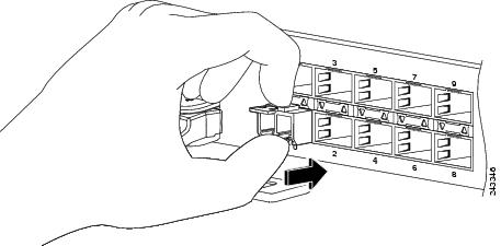 |
What to do next
Note |
When installing an SFP module, you should hear a click as the triangular pin on the bottom of the SFP module snaps into the hole in the receptacle, indicating that the module is correctly seated and secured in the receptacle. Verify that the SFP modules are completely seated and secured in their assigned receptacles on the line card by firmly pushing on each SFP module. |
Removing an Actuator Button SFP Module
To remove this type of SFP module, follow these steps:
SUMMARY STEPS
- Attach an ESD-preventive wrist or ankle strap and follow its instructions for use.
- Disconnect and remove all interface cables from the ports; note the current connections of the cables to the ports on the line card.
- Gently press the actuator button on the front of the SFP module until it clicks and the latch mechanism activates, releasing the SFP module from the port (see the following figure).
- Grasp the actuator button between your thumb and index finger and carefully pull the SFP module from the port.
- Place the removed SFP module on an antistatic mat, or immediately place it in a static shielding bag if you plan to return it to the factory.
- Protect your line card by inserting clean SFP module cage covers into the optical module cage when there is no SFP module installed.
DETAILED STEPS
| Step 1 |
Attach an ESD-preventive wrist or ankle strap and follow its instructions for use. |
| Step 2 |
Disconnect and remove all interface cables from the ports; note the current connections of the cables to the ports on the line card. |
| Step 3 |
Gently press the actuator button on the front of the SFP module until it clicks and the latch mechanism activates, releasing the SFP module from the port (see the following figure). 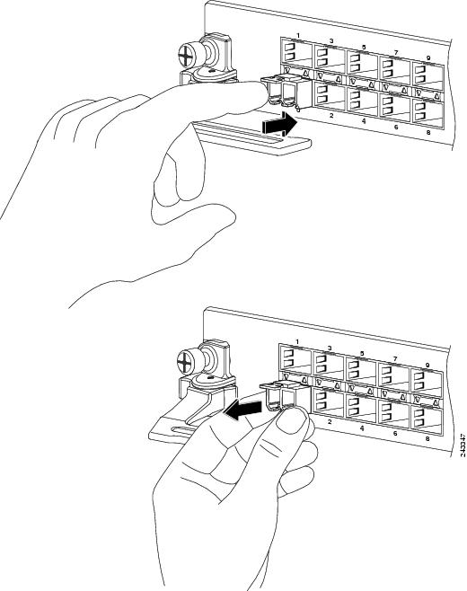 |
| Step 4 |
Grasp the actuator button between your thumb and index finger and carefully pull the SFP module from the port. |
| Step 5 |
Place the removed SFP module on an antistatic mat, or immediately place it in a static shielding bag if you plan to return it to the factory. |
| Step 6 |
Protect your line card by inserting clean SFP module cage covers into the optical module cage when there is no SFP module installed. |
Slide Tab SFP Module
The slide tab SFP module has a tab underneath the front of the module that you use to disengage the module from a port (see the following figure).
Installing a Slide Tab SFP Module
To install this type of SFP module into a line card, follow these steps:
SUMMARY STEPS
- Attach an ESD-preventive wrist or ankle strap and follow its instructions for use.
- Line up the SFP module with the port and gently push on it until it snaps into the slot tightly (see the following figure).
DETAILED STEPS
| Step 1 |
Attach an ESD-preventive wrist or ankle strap and follow its instructions for use. |
| Step 2 |
Line up the SFP module with the port and gently push on it until it snaps into the slot tightly (see the following figure). 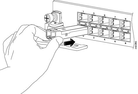 |
What to do next
Note |
When installing an SFP module, you should hear a click as the triangular pin on the bottom of the SFP module snaps into the hole in the receptacle, indicating that the module is correctly seated and secured in the receptacle. Verify that the SFP modules are completely seated and secured in their assigned receptacles on the line card by firmly pushing on each SFP module. |
Removing a Slide Tab SFP Module
To remove this type of SFP module, follow these steps:
SUMMARY STEPS
- Attach an ESD-preventive wrist or ankle strap and follow its instructions for use.
- Disconnect and remove all interface cables from the ports; note the current connections of the cables to the ports on the line card.
- Grasp the SFP module between your thumb and index finger.
- With your thumb, push the slide tab on the bottom front of the SFP module in the direction of the line card to disengage the module from the line card port (see the following figure).
- With the tab still pushed, carefully pull the SFP module from the port as shown in the figure below.
- Place the removed SFP module on an antistatic mat, or immediately place it in a static shielding bag if you plan to return it to the factory.
- Protect your line card by inserting clean SFP module cage covers into the optical module cage when there is no SFP module installed.
DETAILED STEPS
| Step 1 |
Attach an ESD-preventive wrist or ankle strap and follow its instructions for use. |
||
| Step 2 |
Disconnect and remove all interface cables from the ports; note the current connections of the cables to the ports on the line card. |
||
| Step 3 |
Grasp the SFP module between your thumb and index finger. |
||
| Step 4 |
With your thumb, push the slide tab on the bottom front of the SFP module in the direction of the line card to disengage the module from the line card port (see the following figure). 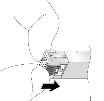 |
||
| Step 5 |
With the tab still pushed, carefully pull the SFP module from the port as shown in the figure below.
 |
||
| Step 6 |
Place the removed SFP module on an antistatic mat, or immediately place it in a static shielding bag if you plan to return it to the factory. |
||
| Step 7 |
Protect your line card by inserting clean SFP module cage covers into the optical module cage when there is no SFP module installed. |
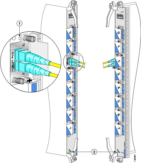
Replacing a SFP on a Line Card that Uses an Articulated Bracket
To replace a failed, defective, or retired SFP from a line card that is currently in service, and using an articulated cable management bracket, proceed as follows:
SUMMARY STEPS
- For a line card with multiple articulated brackets, select the fibers to be removed from the bracket with the SFP to be removed.
- Undo and remove the Velcro from the articulated bracket to release the fibers.
- From the physical location of the SFP to be removed, determine which end of the articulated bracket will be unscrewed:
- Pivot the articulated bracket up or down, depending on which screw was removed.
- Label and disconnect the fibers from the port and put them aside.
- Remove the SFP.
- Replace with the new SFP (or a dust cap if the port is not going to be reused).
- Re-install the fibers that were removed in Step 5. per the labels.
- Pivot the articulated bracket back into position and secure.
- Re-dress and secure the fibers to the articulated bracket with Velcro.
DETAILED STEPS
| Step 1 |
For a line card with multiple articulated brackets, select the fibers to be removed from the bracket with the SFP to be removed. For a line card with a single articulated bracket, begin with Step 2. |
| Step 2 |
Undo and remove the Velcro from the articulated bracket to release the fibers. |
| Step 3 |
From the physical location of the SFP to be removed, determine which end of the articulated bracket will be unscrewed:
|
| Step 4 |
Pivot the articulated bracket up or down, depending on which screw was removed. |
| Step 5 |
Label and disconnect the fibers from the port and put them aside. |
| Step 6 |
Remove the SFP. |
| Step 7 |
Replace with the new SFP (or a dust cap if the port is not going to be reused). |
| Step 8 |
Re-install the fibers that were removed in Step 5. per the labels. |
| Step 9 |
Pivot the articulated bracket back into position and secure. |
| Step 10 |
Re-dress and secure the fibers to the articulated bracket with Velcro. |
10-GE PLIMs
This section provides information specific to the following 10-GE PLIMs:
The following sections provide information about optics modules:
2-Port 10-GE Flex PLIM with XFP Optics Modules
The 2-port 10-GE Flex PLIM supports from one to two pluggable XFP optics modules.
Supported XFP Optics Modules
- Single-mode short reach (SR) XFP module—XFP-10GLR-OC192SR
- Single-mode intermediate reach (IR) XFP module—XFP-10GER-OC192IR
- Single-mode very-long reach (ZR) XFP module—XFP-10GZR-OC192LR
Cisco qualifies the optics that are approved for use with its PLIMs.
Use a single-mode optical fiber that has a modal-field diameter of 8.7 ±0.5 microns (nominal diameter is approximately 10/125 micron) to connect your router to a network.
Ports and LEDs
The 2-port 10-GE Flex PLIM has:
- Two ports that accept XFP optics modules
- Status LED for the PLIM
- Port status LED for each port
The following figure shows shows the front panel of the 2-port 10-GE Flex PLIM.
|
1 |
Port Status LED |
2 |
PLIM Status LED |
The following table describes the PLIM LEDs for the 2-port 10-GE Flex PLIM.
|
LED |
State |
Description |
|---|---|---|
|
PLIM Status |
Green |
PLIM is properly seated and operating correctly. |
|
Yellow |
PLIM has a problem. |
|
|
Off |
PLIM is not properly seated or system power is off. |
|
|
Port Status |
On |
Port is logically active and the laser is on. |
|
Off |
Port is not active. |
Physical Characteristics
- Height—20.6 in. (52.3 cm)
- Depth—11.2 in. (28.5 cm)
- Width—1.8 in. (4.6 cm)
- Weight—8.4 lb (3.8 kg)
- Power consumption—33 W (with two optics modules)
2-Port 10-GE Flex PLIM SPA Support
The 2-Port 10-GE Flex PLIM provides two ports of IEEE 802.3ae-compliant 10 GE WAN/LAN-physical (PHY) layer interfaces and two available Cisco I-Flex shared port adapter (SPA) slots. These slots can support up to up to 2 additional half-height SPAs.
The SPAs supported in the two available Cisco I-Flex shared port adapter (SPA) slots can be Packet over SONET/SDH (PoS) or Ethernet. The following SPAs are supported:
- SPA-5X1GE-V2
- SPA-8X1GE
- SPA-8X1GE-V2
- SPA-10X1GE-V2
- SPA-1X10GE-L-V2
- SPA-1X10GE-WL-V2
- SPA-4XOC3-POS
- SPA-8XOC12-POS
- SPA-2XOC48POS/RPR
- SPA-4XOC48POS/RPR
- SPA-OC192POS-VSR
- SPA-OC192POS-XFP
Refer to the Installing and Removing a Shared Port Adapter chapter of the Cisco CRS-1 SIP and SPA Hardware Installation Guide online here: http://www.cisco.com/en/US/docs/interfaces_modules/shared_port_adapters/install_upgrade/crs/crs1/installation/guide/crsspain.html for instructions on replacing the SPAs.
Refer to the Overview: Cisco CRS-1 Shared Port Adapters chapter of the Cisco CRS-1 SIP and SPA Hardware Installation Guide online here: http://www.cisco.com/en/US/docs/interfaces_modules/shared_port_adapters/install_upgrade/crs/crs1/installation/guide/crsspaov.html for descriptions of each of the supported SPAs.
4-Port 10-GE PLIM with XENPAK Optics Modules
The 4-port 10-GE PLIM supports from one to four pluggable XENPAK optics modules, each providing full-duplex long-wavelength or extra-long-wavelength optics with subscriber connector (SC) fiber-optic interfaces.
Ports and LEDs
The 4-port 10-GE PLIM has:
- Four ports that accept XENPAK optics modules
- Status LED for the PLIM
- Port status LED for each port
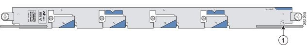
The following figure shows the front panel of the 4-port 10-GE PLIM.
|
1 |
Status LED |
The following table describes the PLIM LEDs for the 4-Port 10-GE XENPAK PLIM.
|
LED |
State |
Description |
|---|---|---|
|
PLIM Status |
Green |
PLIM is properly seated and operating correctly. |
|
Yellow |
PLIM has a problem. |
|
|
Off |
PLIM is not properly seated or system power is off. |
|
|
Port Status |
On |
Port is logically active and the laser is on. |
|
Off |
Port is not active. |
Physical Characteristics
- Height—20.6 in. (52.3 cm)
- Depth—11.2 in. (28.5 cm)
- Width—1.8 in. (4.6 cm)
- Weight—8.4 lb (3.8 kg)
- Power consumption—75 W (with four optics modules)
4-Port 10-GE PLIM with XFP Optics Modules
The 4-port 10-GE XFP PLIM supports from one to four pluggable XFP optics modules.
-
Supported XFP Modules and Port Cabling Specifications lists the XFP optical transceiver modules supported on the 4-port 10-GE XFP PLIM.
-
Supported DWDM XFP Transceivers lists the DWDM XFP transceiver modules supported on the 4-port 10-GE XFP PLIM.
Cisco qualifies the optics that are approved for use with its PLIMs.
For the modules listed, use a single-mode optical fiber that has a modal-field diameter of 8.7 ±0.5 microns (nominal diameter is approximately 10/125 micron) to connect your router to a network.
Ports and LEDs
The 4-port 10-GE XFP PLIM has:
- Four ports that accept XFP optics modules
- Status LED for the PLIM
- LED for each port
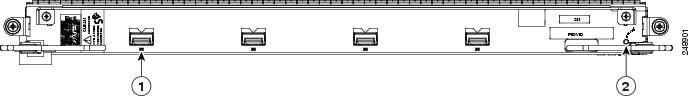
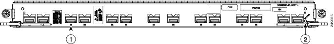
The following figure shows the front panel of the 4-Port 10-GE XFP PLIM.
|
1 |
Port LED (one per port) |
2 |
Status LED |
The following table describes the PLIM LEDs for the 4-Port 10-GE XFP PLIM.
|
LED |
State |
Description |
|---|---|---|
|
Status |
Green |
PLIM is properly seated and operating correctly. |
|
Yellow |
PLIM has a problem. |
|
|
Off |
PLIM is not properly seated or system power is off. |
|
|
Port |
Green |
Port is enabled by software and there is a valid link. |
|
Yellow |
Port LED is yellow under all other conditions not covered by green LED status. |
|
|
Off |
PLIM is not properly seated or system power is off. |
Physical Characteristics
- Height—20.6 in. (52.3 cm)
- Depth—11.2 in. (28.5 cm)
- Width—1.8 in. (4.6 cm)
- Weight—8.4 lb (3.8 kg)
- Power consumption—74 W (with four optics modules)
8-Port 10-GE PLIM with XENPAK Optics Modules
The 8-port 10-GE PLIM supports from one to eight pluggable XENPAK optics modules, each providing full-duplex long-wavelength or extra-long-wavelength optics with subscriber connector (SC) fiber-optic interfaces. This PLIM is a Class 1 laser product.
 Warning |
Class 1 Laser Product. Statement 1008 |
Ports and LEDs
The 8-port 10-GE XENPAK PLIM has:
- Eight ports that accept XENPAK optics modules
- Status LED for the PLIM
- Port status LED for each port
The following figure shows the front panel of the 8-port 10-GE PLIM.
|
1 |
Port 1 Status LED |
2 |
PLIM Status LED |
The following table describes the PLIM LEDs for the 8-Port 10-GE PLIM.
|
LED |
State |
Description |
|---|---|---|
|
PLIM Status |
Green |
PLIM is properly seated and operating correctly. |
|
Yellow |
PLIM has a problem. |
|
|
Off |
PLIM is not properly seated or system power is off. |
|
|
Port Status |
On |
Port is logically active and the laser is on. |
|
Off |
Port is not active. |
Physical Characteristics
- Height—20.6 in. (52.3 cm)
- Depth—11.2 in. (28.5 cm)
- Width—1.8 in. (4.6 cm)
- Weight—8.4 lb (3.8 kg)
- Power consumption—150 W (with eight optics modules)
Oversubscription of 10-GE Ports
Processing on the 10-GE PLIM is performed by two PLIM hardware controllers, each of which can process up to 24 Gbps of traffic. Ports 0 to 3 are associated with one PLIM hardware controller, while ports 4 to 7 are associated with the second PLIM hardware controller. In addition, the PLIM ports are serviced by two MSC hardware controllers, the switching capacity of which is approximately 62 Mpps (million packets per second) each. Each MSC hardware controller is statically assigned to four of the eight ports.
Because of this PLIM design, the placement of the optics modules in the PLIM can greatly affect whether or not oversubscription occurs. For example, if modules are installed in ports 0 and 1, each interface has 10 Gbps of throughput. Adding another module in port 2 causes oversubscription on all interfaces (0, 1, and 2).
If your configuration cannot support oversubscription, use the following guidelines to determine the PLIM ports in which to install optics modules:
- Do not install more than four optics modules in each PLIM.
- Use the following port arrangements to provide optimal performance for up to four 10-GE interfaces in a 10-GE PLIM:
|
Port Numbers |
||||
|
Option 1 |
0 |
2 |
5 |
7 |
|
Option 2 |
4 |
4 |
4 |
6 |
If your configuration can support oversubscription and you want to install more than four optics modules in a PLIM, we recommend that you install additional modules in empty ports, alternating between upper and lower ports and odd and even ports. For example, if you install a fifth optics module in an odd port in the upper set of ports (0 to 3), be sure to install the next module in an even port in the lower set of ports (4 to 7), and so on.
8-Port 10-GE PLIM with XFP Optics Modules
The 8-port 10-GE XFP PLIM supports from one to eight pluggable XFP optics modules.
Supported XFP Optics Modules
-
Supported XFP Modules and Port Cabling Specifications lists the XFP optical transceiver modules supported on the 8-port 10-GE XFP PLIM.
-
Supported DWDM XFP Transceivers lists the DWDM XFP transceiver modules supported on the 8-port 10-GE XFP PLIM.
Cisco qualifies the optics that are approved for use with its PLIMs.
For the modules listed, use a single-mode optical fiber that has a modal-field diameter of 8.7 ±0.5 microns (nominal diameter is approximately 10/125 micron) to connect your router to a network.
Ports and LEDs
The 8-port 10-GE XFP PLIM has:
- Eight ports that accept XFP optics modules
- Status LED for the PLIM
- LED for each port
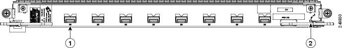
The following figure shows the front panel of the 8-Port 10-GE XFP PLIM.
|
1 |
Port LED (one per port) |
2 |
Status LED |
The following table describes the PLIM LEDs for the 8-Port 10-GE XFP PLIM.
|
LED |
State |
Description |
|---|---|---|
|
Status |
Green |
PLIM is properly seated and operating correctly. |
|
Yellow |
PLIM has a problem. |
|
|
Off |
PLIM is not properly seated or system power is off. |
|
|
Port |
Green |
Port is enabled by software and there is a valid link. |
|
Yellow |
Port LED is yellow under all other conditions not covered by green LED status. |
|
|
Off |
PLIM is not properly seated or system power is off. |
Physical Characteristics
- Height—20.6 in. (52.3 cm)
- Depth—11.2 in. (28.5 cm)
- Width—1.8 in. (4.6 cm)
- Weight—8.4 lb (3.8 kg)
- Power consumption—88 W (with eight optics modules)
14-Port 10-GE PLIM with XFP Optics Modules
The 14-port 10-GE XFP PLIM supports from one to fourteen pluggable XFP optics modules.
Supported XFP Optics Modules
Supported XFP Modules and Port Cabling Specifications lists the XFP optical transceiver modules supported on the 14-port 10-GE XFP PLIM. Supported DWDM XFP Transceivers lists the DWDM XFP transceiver modules supported on the 14-port 10-GE XFP PLIM.
Cisco qualifies the optics that are approved for use with its PLIMs.
Note |
The 14-port XFP PLIM has a fixed power budget for the pluggable XFP optics. See XFP Optics Power Management section for detailed information. |
For the modules listed, use a single-mode optical fiber that has a modal-field diameter of 8.7 ±0.5 microns (nominal diameter is approximately 10/125 micron) to connect your router to a network. The following figure shows the front panel of the 14-Port 10-GE XFP PLIMs.
Ports and LEDs
The 14-port 10-GE XFP PLIM has:
- Fourteen ports that accept XFP optics modules
- Status LED for the PLIM
- LED for each port
|
1 |
Port LED (one per port) |
2 |
Status LED |
The following table describes the PLIM LEDs for the 14-Port 10-GE XFP PLIM.
|
LED |
State |
Description |
|---|---|---|
|
PLIM Status |
Green |
PLIM is properly seated and operating correctly. |
|
Yellow |
PLIM is powered on, but initializing. |
|
|
Off |
PLIM is not properly seated, system power is off, or power up did not complete successfully. |
|
|
Port |
Green |
Port is enabled by software and there is a valid link. |
|
Yellow |
Port LED is yellow under all other conditions not covered by green LED status. |
|
|
Off |
PLIM is not properly seated or system power is off. |
Physical Characteristics
- Height—20.6 in (52.2 cm)
- Depth—11.2 in (28.4 cm)
- Width—1.8 in (4.49 cm)
- Weight—7.85 lbs (3.55 kg)
- Power consumption—150 W (115 W with no optics installed, 35 W optics budget)
20-Port 10-GE PLIM with XFP Optics Modules
The 20-port 10-GE XFP PLIM supports from one to twenty pluggable XFP optics modules.
Supported XFP Optics Modules
Supported XFP Modules and Port Cabling Specifications lists the XFP optical transceiver modules supported on the 20-port 10-GE XFP PLIM. Supported DWDM XFP Transceivers lists the DWDM XFP transceiver modules supported on the 20-port 10-GE XFP PLIM.
Cisco qualifies the optics that are approved for use with its PLIMs.
Note |
The 20-port XFP PLIM has a fixed power budget for the pluggable XFP optics. See XFP Optics Power Management section for detailed information. |
For the modules listed, use a single-mode optical fiber that has a modal-field diameter of 8.7 ±0.5 microns (nominal diameter is approximately 10/125 micron) to connect your router to a network.
Ports and LEDs
The 20-port 10-GE XFP PLIM has:
- Twenty ports that accept XFP optics modules
- Status LED for the PLIM
- Port status LED for each port
The following figure shows the front panel of the 20-Port 10-GE XFP PLIMs.
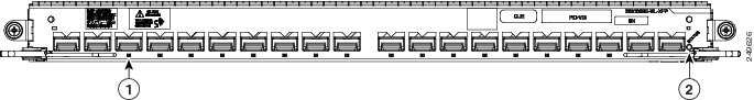
|
1 |
Port LED (one per port) |
2 |
Status LED |
The following table describes the PLIM LEDs for the 20-Port 10-GE XFP PLIM.
|
LED |
State |
Description |
|---|---|---|
|
PLIM Status |
Green |
PLIM is properly seated and operating correctly. |
|
Yellow |
PLIM is powered on, but initializing. |
|
|
Off |
PLIM is not properly seated, system power is off, or power up did not complete successfully. |
|
|
Port |
Green |
Port is enabled by software and there is a valid link. |
|
Yellow |
Port LED is yellow under all other conditions not covered by green LED status. |
|
|
Off |
PLIM is not properly seated or system power is off. |
Physical Characteristics
- Height—20.6 in (52.2 cm)
- Depth—11.2 in (28.4 cm)
- Width—1.8 in (4.49 cm)
- Weight—8.45 lb (3.82 kg)
- Power consumption—150 W (120 W with no optics installed, 30 W optics budget)
40-Port 10-GE PLIM with SFP+ Optics Modules
Note |
In the enhanced chassis, all 40 ports of this PLIM can be used. In the legacy chassis, this PLIM is operated in 200G mode as a 20-port 10-GE SFP+ PLIM. In this case, only the 20 ports on the right are enabled. |
The 40-port 10-GE SFP+ PLIM supports from one to forty pluggable SFP+ optics modules.
Note |
For more information about SFP+ optics modules, see SFP+ Module Connections and SFP+ Module Cabling and Connection Equipment. |
Ports and LEDs
The 40-port 10-GE SFP+ PLIM has:
- Forty ports that accept SFP+ optics modules
- Status LED for the PLIM
- Port status LED for each port
Note |
For this PLIM, a time interval of three seconds is required after removing, and before re-inserting the SFP+ optics modules. |
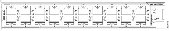
The following figure shows the front panel of the 40-Port 10-GE SFP+ PLIMs.

|
1 |
Port LED (one per port) |
2 |
Status LED |
The 40-Port 10-GE PLIM comprises two sets of twenty ports, each of which are connected to a dedicated Network Processor. When operated in the legacy chassis, the PLIM operates in 200G mode, in which the top set of ports and their Network Processor are deactivated due to thermal constraints. In 200G mode, the port numbering will be different than 400G mode and will start with 0 for the port that is labeled 20 in 400G mode. The faceplate labels therefore include two port numbers for the ports that are active in 200G Mode, as shown in the following figure.
In the enhanced chassis, the 40-Port 10-GE PLIM may optionally operate in Green mode, in which twenty of the ports are deactivated (using the CLI) to save power. In Green mode, the port numbering follows the 400G mode model, which results in only ports 20-39 being active. Ports 0-19 will not be visible in the CLI when the card is in Green mode. Therefore, the port numbers for ports used in Green mode will not change when the card is converted to 400G mode.
The following table describes the PLIM LEDs for the 40-Port 10-GE SFP+ PLIM.
|
LED |
State |
Description |
|---|---|---|
|
PLIM Status |
Green |
PLIM is properly seated and operating correctly. |
|
Yellow |
PLIM is powered on, but initializing. |
|
|
Off |
PLIM is not properly seated, system power is off, or power up did not complete successfully. |
|
|
Port |
Green |
Port is enabled by software and there is a valid link. |
|
Yellow |
Port LED is yellow under all other conditions not covered by green LED status. |
|
|
Off |
PLIM is not properly seated or system power is off. |
Physical Characteristics
- Height—20.6 in (52.2 cm)
- Depth—11.2 in (28.4 cm)
- Width—1.8 in (4.49 cm)
- Weight—7.55 lbs (3.55 kg)
- Power consumption—110 W
Note |
In Cisco IOS XR Release 5.3.2 or earlier versions, High-powered optics such as SFP-10G-ER, SFP-10G-ZR and DWDM can only be inserted in ports 30-39 of the PLIM. These high-powered optics if inserted in ports 0-29, can cause a boot failure. |
Note |
In Cisco IOS XR Release 6.0.1 and later versions, up to 30 high-powered optics on the PLIM are supported. Only 15 high-power optics each can be inserted in 0-19 ports (upper slice) and 20-39 ports (lower slice). The low power optics can be inserted in any of the remaining ports. Users cannot insert more than 15 high-power optics in a given slice. |
10-GE PLIM with DWDM XENPAK Modules
In addition to 10-GE modules, the 10-GE PLIM supports from one to four pluggable dense wavelength-division multiplexing (DWDM) XENPAK optics modules, each providing full-duplex long-wavelength DWDM optics with SC fiber-optic interfaces. See the 8-Port 10-GE PLIM with XENPAK Optics Modules section for general information about the PLIM.
When using DWDM optics modules on your 10-GE PLIM, an empty slot must exist next to each installed DWDM module to provide optimal cooling for the DWDM optics. For this reason, you can install up to four DWDM XENPAK modules in the 10-GE PLIM. Given this restriction and to optimize the PLIM for oversubscription, you should use port positions 0, 2, 5, and 7.
Caution |
One to four DWDM XENPAK modules can be installed. If one DWDM XENPAK module is installed, a maximum of four XENPAK modules can be installed in the PLIM. |
The following table lists the part numbers and frequencies of the DWDM XENPAK optics modules that are compatible with the 10-GE PLIM.
|
Part Number |
Frequency (THz) |
Center
Wavelength (nm)
|
||
|---|---|---|---|---|
|
DWDM-XENPAK-30.33 |
195.9 |
1530.33 |
||
|
DWDM-XENPAK-31.12 |
195.8 |
1531.12 |
||
|
DWDM-XENPAK-31.90 |
195.7 |
1531.90 |
||
|
DWDM-XENPAK-32.68 |
195.6 |
1532.68 |
||
|
DWDM-XENPAK-34.25 |
195.4 |
1534.25 |
||
|
DWDM-XENPAK-35.04 |
195.3 |
1535.04 |
||
|
DWDM-XENPAK-35.82 |
195.2 |
1535.82 |
||
|
DWDM-XENPAK-36.61 |
195.1 |
1536.61 |
||
|
DWDM-XENPAK-38.19 |
194.9 |
1538.19 |
||
|
DWDM-XENPAK-38.98 |
194.8 |
1538.98 |
||
|
DWDM-XENPAK-39.77 |
194.7 |
1539.77 |
||
|
DWDM-XENPAK-40.56 |
194.6 |
1540.56 |
||
|
DWDM-XENPAK-42.14 |
194.4 |
1542.14 |
||
|
DWDM-XENPAK-42.94 |
194.3 |
1542.94 |
||
|
DWDM-XENPAK-43.73 |
194.2 |
1543.73 |
||
|
DWDM-XENPAK-44.53 |
194.1 |
1544.53 |
||
|
DWDM-XENPAK-46.12 |
193.9 |
1546.12 |
||
|
DWDM-XENPAK-46.92 |
193.8 |
1546.92 |
||
|
DWDM-XENPAK-47.72 |
193.7 |
1547.72 |
||
|
DWDM-XENPAK-48.51 |
193.6 |
1548.51 |
||
|
DWDM-XENPAK-50.12 |
193.4 |
1550.12 |
||
|
DWDM-XENPAK-50.92 |
193.3 |
1550.92 |
||
|
DWDM-XENPAK-51.72 |
193.2 |
1551.72 |
||
|
DWDM-XENPAK-52.52 |
193.1 |
1552.52 |
||
|
DWDM-XENPAK-54.13 |
192.9 |
1554.13 |
||
|
DWDM-XENPAK-54.94 |
192.8 |
1554.94 |
||
|
DWDM-XENPAK-55.75 |
192.7 |
1555.75 |
||
|
DWDM-XENPAK-56.55 |
192.6 |
1556.55 |
||
|
DWDM-XENPAK-58.17 |
192.4 |
1558.17 |
||
|
DWDM-XENPAK-58.98 |
192.3 |
1558.98 |
||
|
DWDM-XENPAK-59.79 |
192.2 |
1559.79 |
||
|
DWDM-XENPAK-60.61 |
192.1 |
1560.61 |
10-GE Tunable WDMPHY PLIM
The 4-port 10-GE WDMPHY PLIM provides four 10-GE dense wavelength-division multiplexing (DWDM) interfaces that support both G.709 Generic Forward Error Correction (GFEC) and high-gain Enhanced Forward Error Correction (EFEC) and extend reach up to 2000 km without requiring signal regeneration. The 4-port 10-GE WDMPHY PLIM is also completely tunable across the C band with 50-GHz spacing and supports router-to-router SONET/SDH-like OAMP.
The 4-port 10-GE WDMPHY PLIM provides four 10-GE DWDM lucent connector (LC) fiber-optic interfaces. This PLIM is a Class 1 laser product.
Warning |
Class 1 Laser Product. Statement 1008 |
Ports and LEDs
The 4-port 10-GE WDMPHY PLIM has the following LEDs:
- Status LED for the PLIM
- Three port LEDs that indicate the port status
The following figure shows the front panel of the 4-port 10-GE WDMPHY PLIM.
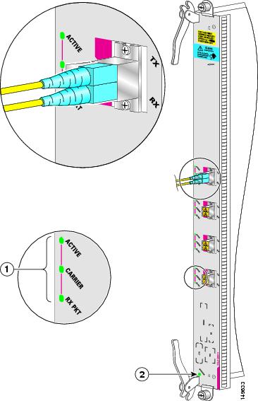
|
1 |
Port LEDs |
2 |
Status LED |
The following table describes the PLIM LEDs for the 10-GE WDMPHY PLIM.
|
LED |
State |
Description |
|---|---|---|
|
Status |
Green |
PLIM is properly seated and operating correctly. |
|
Yellow |
PLIM has a problem. |
|
|
Off |
PLIM is not properly seated or system power is off. |
|
|
Active |
Green |
Interface is up. |
|
Off |
Interface is down. |
|
|
Carrier |
On |
No error indicated. |
|
Off |
OTN loss of frame (LOF) if G.709 is enabled; loss of block lock if G.709 is disabled. |
|
|
Rx Pkt |
Green (flashing) |
Packets are being received on the port. |
|
Off |
No packets are being received on the port. |
Physical Characteristics
- Height—20.6 in. (52.3 cm)
- Depth—11.2 in. (28.5 cm)
- Width—1.8 in. (4.6 cm)
- Weight—8.6 lb (3.9 kg)
- Power consumption—150 W
Supported XFP Modules and Port Cabling Specifications
The following table lists the XFP modules supported on the 8-port 10-GE XFP, 4-port 10-GE XFP, 20-port 10-GE XFP, and 14-port 10-GE XFP PLIMs, and provides cabling specifications.
|
Part Number |
Description |
Wavelength (nm) |
Fiber Type |
Typical Maximum Distance |
||
|---|---|---|---|---|---|---|
|
XFP-10G-MM-SR, V02
|
Multirate 10GBASE-SR |
850 |
MMF |
85.3 to 984.3 feet (26 m to 300 m) |
||
|
XFP10GLR-192SR-L, V01 |
Low Power multirate XFP supporting 10GBASE-LR and OC-192 SR |
1310 |
SMF |
6.213 miles (10 km) |
||
|
XFP10GER-192IR-L, V01 |
Low Power multirate XFP supporting 10GBASE-ER and OC-192 IR |
1550 |
SMF |
24.85 miles (40 km) |
||
|
XFP-10G-ZR-OC192LR, V03 |
Multirate 10GBASE-ZR and OC-192/STM-64 LR-2 XFP |
1550 |
SMF |
49.70 miles (80 km) |
XFP Optics Power Management
The 20- and 14-port XFP PLIMs have a fixed power budget for the pluggable XFP optics:
- The 20-port 10-GE XFP PLIM has a power budget of 30 watts. It can have all 20 ports filled with XFP10GLR-192SR-L V01 (10KM -> 1.5W) XFPs. If you use optics other than SR, such as XFP10GER-192IR-L V01 (40KM -> 2.5W) XFPs you must be careful not to exceed the power budget, which may result in some ports remaining unpowered. Also, unsupported optics will not power up. Cisco IOS XR software enables the ports in a sequence that allows the configuration to remain within the optics power budget.
- The 14-port 10-GE XFP PLIM has a power budget of 30 watts. You can have all 14 ports filled with a combination of SR (1.5W) 10km XFPs and LR (2.5W) 40km XFPs. If you use optics other than SR or LR, you must be careful not to exceed the power budget, which may result in some ports remaining unpowered. Cisco IOS XR software enables the ports in a sequence that allows the configuration to remain within the optics power budget.
- For more details on how the software controls PLIM power consumption, see Cisco IOS XR Interface and Hardware Component Command Reference for the Cisco CRS Router .
The XFP pluggable optics for the 20- and 14-port XFP PLIMs have different power consumptions based on their reach and type. The number of XFPs which will power up in a PLIM depends on their aggregate power consumption within the allocated power budget.
During XFP insertion, the power is allotted to the optics based on the insertion order of the XFPs. On boot up and reload, priority is re-assigned to the lower numbered ports.
The recommended insertion sequence is to alternate between inserting XFPs in lowest numbered ports for each interface device driver ASIC to avoid oversubscription. The insertion order for a 20 Port PLIM would be “0,10,1,11,2,12,...9,19.” For a 14 Port PLIM, insertion order would be “0,7,1,8,...6,13.”
If the PLIM power budget is exceeded, a console log message is displayed informing the user the power budget has been exceeded and to remove the XFP:
plim_[x]ge: %L2-PLIM-6-NO_POWER_XFP : Port <port number>, Not enough power available
to power XFP, powering off
Any unpowered XFPs should be removed to ensure that the same XFPs that were powered before a reload are the same XFPs that are powered after a reload. Removing the unpowered XFPs prevents the powered down XFPs being given priority after the reload.
A show command is provided to indicate how much of the XFP power budget is currently used and how much power an XFP is consuming:
show controllers tenGigE 0/3/0/0 internalSupported DWDM XFP Transceiver Modules
The following table lists the DWDM XFP transceiver modules supported on the 8-port 10-GE XFP, 4-port 10-GE XFP, 20-port 10-GE XFP, and 14-port 10-GE XFP PLIMs, and provides center wavelength, frequency, and channel numbering specifications.
|
Part Number |
Description |
Channel ID |
Frequency (THz) |
Center Wavelength (nm) |
|---|---|---|---|---|
|
DWDM-XFP-60.61 V02 |
Cisco 10GBASE-DWDM 1560.61 nm XFP (100 GHz ITU grid) |
4 |
192.1 |
1560.61 |
|
DWDM-XFP-59.79 V02 |
Cisco 10GBASE-DWDM 1559.79 nm XFP (100 GHz ITU grid) |
6 |
192.2 |
1559.79 |
|
DWDM-XFP-58.98 V02 |
Cisco 10GBASE-DWDM 1558.98 nm XFP (100 GHz ITU grid) |
8 |
192.3 |
1558.98 |
|
DWDM-XFP-58.17 V02 |
Cisco 10GBASE-DWDM 1558.17 nm XFP (100 GHz ITU grid) |
10 |
192.4 |
1558.17 |
|
DWDM-XFP-56.55 V02 |
Cisco 10GBASE-DWDM 1556.55 nm XFP (100 GHz ITU grid) |
14 |
192.6 |
1556.55 |
|
DWDM-XFP-55.75 V02 |
Cisco 10GBASE-DWDM 1555.75 nm XFP (100 GHz ITU grid) |
16 |
192.7 |
1555.75 |
|
DWDM-XFP-54.94 V02 |
Cisco 10GBASE-DWDM 1554.94 nm XFP (100 GHz ITU grid) |
18 |
192.8 |
1554.94 |
|
DWDM-XFP-54.13 V02 |
Cisco 10GBASE-DWDM 1554.13 nm XFP (100 GHz ITU grid) |
20 |
192.9 |
1554.13 |
|
DWDM-XFP-52.52 V02 |
Cisco 10GBASE-DWDM 1552.52 nm XFP (100 GHz ITU grid) |
24 |
193.1 |
1552.52 |
|
DWDM-XFP-51.72 V02 |
Cisco 10GBASE-DWDM 1551.72 nm XFP (100 GHz ITU grid) |
26 |
193.2 |
1551.72 |
|
DWDM-XFP-50.92 V02 |
Cisco 10GBASE-DWDM 1550.92 nm XFP (100 GHz ITU grid) |
28 |
193.3 |
1550.92 |
|
DWDM-XFP-50.12 V02 |
Cisco 10GBASE-DWDM 1550.12 nm XFP (100 GHz ITU grid) |
30 |
193.4 |
1550.12 |
|
DWDM-XFP-48.51 V02 |
Cisco 10GBASE-DWDM 1548.51 nm XFP (100 GHz ITU grid) |
34 |
193.6 |
1548.51 |
|
DWDM-XFP-47.72 V02 |
Cisco 10GBASE-DWDM 1547.72 nm XFP (100 GHz ITU grid) |
36 |
193.7 |
1547.72 |
|
DWDM-XFP-46.92 V02 |
Cisco 10GBASE-DWDM 1546.92 nm XFP (100 GHz ITU grid) |
38 |
193.8 |
1546.92 |
|
DWDM-XFP-46.12 V02 |
Cisco 10GBASE-DWDM 1546.12 nm XFP (100 GHz ITU grid) |
40 |
193.9 |
1546.12 |
|
DWDM-XFP-44.53 V02 |
Cisco 10GBASE-DWDM 1544.53 nm XFP (100 GHz ITU grid) |
44 |
194.1 |
1544.53 |
|
DWDM-XFP-43.73 V02 |
Cisco 10GBASE-DWDM 1543.73 nm XFP (100 GHz ITU grid) |
46 |
194.2 |
1543.73 |
|
DWDM-XFP-42.94 V02 |
Cisco 10GBASE-DWDM 1542.94 nm XFP (100 GHz ITU grid) |
48 |
194.3 |
1542.94 |
|
DWDM-XFP-42.14 V02 |
Cisco 10GBASE-DWDM 1542.14 nm XFP (100 GHz ITU grid) |
50 |
194.4 |
1542.14 |
|
DWDM-XFP-40.56 V02 |
Cisco 10GBASE-DWDM 1540.56 nm XFP (100 GHz ITU grid) |
54 |
194.8 |
1540.56 |
|
DWDM-XFP-39.77 V02 |
Cisco 10GBASE-DWDM 1539.77 nm XFP (100 GHz ITU grid) |
56 |
194.7 |
1539.77 |
|
DWDM-XFP-38.98 V02 |
Cisco 10GBASE-DWDM 1539.98 nm XFP (100 GHz ITU grid) |
58 |
194.8 |
1539.98 |
|
DWDM-XFP-38.19 V02 |
Cisco 10GBASE-DWDM 1538.19 nm XFP (100 GHz ITU grid) |
60 |
194.9 |
1538.19 |
|
DWDM-XFP-36.61 V02 |
Cisco 10GBASE-DWDM 1536.61 nm XFP (100 GHz ITU grid) |
64 |
195.1 |
1536.61 |
|
DWDM-XFP-35.82 V02 |
Cisco 10GBASE-DWDM 1535.82 nm XFP (100 GHz ITU grid) |
66 |
195.2 |
1535.82 |
|
DWDM-XFP-35.04 V02 |
Cisco 10GBASE-DWDM 1535.04 nm XFP (100 GHz ITU grid) |
68 |
195.3 |
1535.04 |
|
DWDM-XFP-34.25 V02 |
Cisco 10GBASE-DWDM 1534.25 nm XFP (100 GHz ITU grid) |
70 |
195.4 |
1534.25 |
|
DWDM-XFP-32.68 V02 |
Cisco 10GBASE-DWDM 1532.68 nm XFP (100 GHz ITU grid) |
74 |
195.6 |
1532.68 |
|
DWDM-XFP-31.90 V02 |
Cisco 10GBASE-DWDM 1531.90 nm XFP (100 GHz ITU grid) |
76 |
195.7 |
1531.90 |
|
DWDM-XFP-31.12 V02 |
Cisco 10GBASE-DWDM 1531.12 nm XFP (100 GHz ITU grid) |
78 |
195.8 |
1531.12 |
|
DWDM-XFP-30.33 V02 |
Cisco 10GBASE-DWDM 1530.33 nm XFP (100 GHz ITU grid) |
80 |
195.5 |
1530.33 |
SFP+ Module Connections
The enhanced small form-factor pluggable (SFP+) module is an enhanced version of the SFP module, supporting data rates up to 10 Gbps. The SFP+ module is a hot-swappable input/output (I/O) device that plugs into an Ethernet SFP+ port on the 40-Port 10-GE PLIM. It has optical interoperability with 10GBASE XENPAK, 10GBASE X2, and 10GBASE XFP interfaces on the same link.
The 40-Port 10-GE PLIM accepts only the SFP+ modules listed as supported in this document. An SFP+ module check is run every time an SFP+ is inserted, and only SFP+ modules that pass this check can be used by the 40-port 10-GE PLIM.
SFP+ modules exist for technologies other than GE and for products other than the 40-Port 10-GE PLIM. However, the information in this document pertains only to SFP+ modules that plug into the 40-Port 10-GE PLIM ports.
The SFP+ module has a receiver port (RX) and a transmitter port (TX) that compose one optical interface.
|
SFP Module Product Number |
SFP Module |
Description |
||
|---|---|---|---|---|
|
SFP-10G-SR |
SFP+ transceiver module for MMF, 850-nm wavelength, LC duplex connector |
Supports a link length of 26m on standard Fiber Distributed Data Interface (FDDI)-grade multimode fiber (MMF). Using 2000MHz km MMF (OM3), up to 300m link lengths are possible. Using 4700MHz 1 km MMF (OM4), up to 400m link lengths are possible.
|
||
|
SFP-10G-SR-X |
10GBASE-SR SFP+ transceiver module (Multirate optics) |
|||
|
SFP-10G-LR |
SFP+ transceiver module for SMF, 1310-nm wavelength, LC duplex connector |
Supports a link length of 10 kilometers on standard single-mode fiber (SMF, G.652). |
||
|
SFP-10G-LR-X |
10GBASE-LR SFP+ transceiver module (Multirate optics) |
|||
|
SFP-10G-LR-M |
10GBASE-LRM SFP+ transceiver module for MMF and SMF, 1310-nm wavelength, LC duplex connector |
Supports link lengths of 220m on standard Fiber Distributed Data Interface (FDDI)-grade multimode fiber (MMF).
|
||
|
SFP-10G-ER |
SFP+ transceiver module for SMF, 1550-nm, LC duplex connector |
Supports a link length of up to 40 kilometers on standard single-mode fiber (SMF, G.652). |
||
|
SFP-10G-ZR |
SFP+ transceiver module for SMF, 1550-nm, LC duplex connector |
Supports link lengths of up to about 80 kilometers on standard single-mode fiber (SMF, G.652). This interface is not specified as part of the 10GE standard and is instead built according to Cisco specifications. |
|
Product |
Type |
Transmit
Power (dBm) 1
|
Receive Power
(dBm)
|
Transmit and Receive Wavelength (nm) |
||||
|---|---|---|---|---|---|---|---|---|
|
SFP-10G-SR SFP-10G-SR-X |
10GBASE-SR 850nm MMF |
Maximum: -1.2
Minimum: -7.3 |
Maximum: -1.0 Minimum: -9.9 |
840 to 860 |
||||
|
SFP-10G-LR SFP-10G-LR-X |
10GBASE-LR 1310nm SMF |
Maximum: 0.5 Minimum: -8.2 |
Maximum: 0.5 Minimum: -14.4 |
1260 to 1355 |
||||
|
SFP-10G-LR-M |
10GBASE-LRM 1310nm MMF and SMF |
Maximum: 0.5 Minimum: -6.5 |
Maximum: 0.5 Minimum:
-8.4 (in average and -6.4 in OMA)
|
1260 to 1355 |
||||
|
SFP-10G-ER |
10GBASE-ER 1550nm SMF |
Maximum: 4.0 Minimum: -4.7 |
Maximum: -1 Minimum: -15.8 |
1530 to 1565 |
||||
|
SFP-10G-ZR |
10GBASE-ZR 1550nm SMF |
Optical output power maximum: 0 Optical output power minimum: 4.0 |
- |
Transmitter: 1530 to 1565 Receiver: 1260 to 1565 |
SFP+ Module Cabling and Connection Equipment
The following table provides cabling specifications for the SFP+ modules that can be installed on the 40-Port 10-GE PLIM. Note that all SFP+ ports have dual LC/PC connectors.
The minimum cable distance for the SFP-10G-SR, LR, and ER is 6.5 feet (2 m).
|
SFP Modules |
Wavelength (nm) |
Fiber Type |
Core Size (micron) |
Modal Bandwidth (MHz/km) |
MaximumCable Distance |
|---|---|---|---|---|---|
|
SFP-10G-SR SFP-10G-SR-X |
850 |
MMF Multimode fiber only. |
62.5 |
160 |
85.3 ft (26 m) |
|
62.5 |
200 |
108.3 ft (33 m) |
|||
|
50.0 |
400 |
216.5 ft (66 m) |
|||
|
50.0 |
500 |
269 ft (82 m) |
|||
|
50.0 |
2000 |
984.3 ft (300 m) |
|||
|
50.0 |
4700 |
1312.3 ft (400 m) |
|||
|
SFP-10G-LR SFP-10G-LR-X |
1310 |
SMF |
G.652 |
— |
6.2 miles (10 km) |
|
SFP-10G-LR-M |
1310 |
MMF SMF |
62.5 |
500 |
721.8 ft (220 m) |
|
50.0 |
400 |
328.1 ft (100 m) |
|||
|
50.0 |
500 |
721.8 ft (220 m) |
|||
|
G.652 |
— |
984.3 ft (300 m) |
|||
|
SFP-10G-ER Requires 5 dB 1550nm fixed loss attenuator for < 20km. Attenuator is available as a spare. (PID: 15216 ATT LC 5=) |
1550 |
SMF |
G.652 |
— |
24.9 miles (40 km) Links longer than 30km are considered engineered links as per IEEE 802.3ae. 3. Requires 5 dB 1550nm fixed loss attenuator for < 20km. Attenuator is available as a spare. The part number is 15216 ATT LC 5=. |
|
Product |
Bail Latch Color |
|---|---|
|
Cisco SFP-10G-SR |
Beige |
|
Cisco SFP-10G-LR |
Blue |
|
Cisco SFP-10G-ER |
Red |
|
Cisco SFP-10G-ZR |
Green |
Cabling and Specifications for 10-GE PLIMs
The following sections provide information about specifications and cabling for 10-GE Ethernet PLIMs:
Specifications for 10-GE XENPAK Interfaces
The 10-GE XENPAK optics modules use single-mode fiber-optics with SC connectors. The maximum distance for single-mode installations is determined by the amount of light loss in the fiber path. If your environment requires the light to travel close to the typical maximum distance (as listed in the following table), you should use an optical time domain reflectometer (OTDR) to measure the power loss.
Two types of 10-GE XENPAK interfaces are available: long wavelength, 1310 nanometers (nm), and extra-long wavelength, 1550 nm.
The following table lists the specifications for the 10-GE XENPAK interfaces. The actual distance in any given case depends on the quality of the fiber connected to the transceiver.
|
Specification |
Long Wavelength |
Extra Long Wavelength |
||||
|---|---|---|---|---|---|---|
|
Target distance |
6.2 miles (10 km) |
24.8 miles (40 km)
|
||||
|
Operating Wavelength Range |
1260-1355 nm |
1530-1565 nm |
||||
|
Transmitter |
||||||
|
Transmit optical power range |
–8.2 to +0.5 dBm |
–4.7 to +4.0 dBm |
||||
|
Receiver |
||||||
|
Receive optical power range |
–14.4 to +0.5 dBm |
–15.8 to –1.0 dBm |
||||
|
Optical Link |
||||||
|
Fiber type |
G.652 (single-mode fiber [SMF]) |
G.652 (SMF) |
||||
|
Optical power budget |
9.4 dB |
15 dB |
||||
|
Compliance |
IEEE 802.3ae 10GBASE-LR |
IEEE 802.3ae 10GBASE-ER |
||||
 Tip |
The abbreviation dBm (decibel) indicates dB referenced to 1.0 milliwatt. One milliwatt is zero dBm. |
Specifications for 10-GE DWDM XENPAK Interfaces
The 10-GE DWDM XENPAK optics modules use single-mode fiber-optics with SC connectors. When the input power is more than the maximum receive power, you need an attenuator installed in the RX port to bring the optical power to the receiver to the correct range.
The 10-GE DWDM XENPAK interfaces are long-wavelength, 1310 nanometers (nm).
The following table lists the specifications of the 10-GE DWDM XENPAK interfaces.
|
Specification |
Value |
||
|---|---|---|---|
|
Transmitter |
|||
|
Spectral width
|
0.2 nm |
||
|
Transmit optical power range |
–1 to +3 dBm |
||
|
Side-mode suppression ratio (SMSR) |
30 dB |
||
|
Transmitter extinction ratio (OMI) |
9 dB |
||
|
Receiver |
|||
|
Receiver optical input wavelength |
1530 to 1565 nm |
||
|
Receiver damage threshold |
–1 dBm |
||
|
Dispersion tolerance |
–500 to 1600 ps/nm |
||
|
Receive optical power range
|
–24 to –7 dBm |
||
Caution |
Input optical power to the XENPAK module must be less than –1 dBm to avoid damaging the receiver. |
Caution |
Never connect a fiber loopback to the TX and RX ports without an attenuator. Use a 15 dB attenuator for direct fiber loopbacks. |
Specifications for 10-GE DWDM Tunable Interfaces
Each 10-GE DWDM line interface provides one 10-Gbps, long-reach, ITU-compliant, 50-GHz-spaced optical interface using LC connectors supporting 10-GE LAN PHY interfaces. The output line interface is tunable across 82 adjacent 50-GHz wavelengths, enabling support for C-Band DWDM networks. The following table lists the optics specifications of the interfaces on the 10-GE WDMPHY PLIM.
|
Specification |
Value |
|---|---|
|
Nominal wavelengths (lambdaTnom) |
C-Band Unit: Fully tunable from 1529.55 to 1561.84 |
|
Spectral range (lambdaTmin to lambdaTmax) |
1530 to 1561 nm |
|
Spectral width at 20dB (lambda delta20) |
25 GHz |
|
Optical Transmitter |
|
|
Type |
Lithium niobate external modulator |
|
Output power (PTmin to PTmax) |
+3 dBm, +6 dBm |
|
Required optical return loss, minimum (ORLmin) |
27 dB |
|
Extinction ratio, minimum (reminx) |
>10.5 dB |
|
Optical Receiver |
|
|
Type |
Avalanche photo diode (APD) |
|
Chromatic dispersion tolerance (DLRmax) |
Up to ±1200 ps/nm (2 dB penalty) |
|
Reflectance between far-end TX and near-end RX (maximum) |
–27 dB |
|
Receiver reflectance (maximum) |
–14 dB |
|
Input wavelength bandwidth (lambdac_rx) |
1290 nm to 1605 nm |
The following table indicates the optical performance of the 10-GE WDMPHY PLIM.
|
OSNR
|
FEC Type |
Pre-FEC BER |
Post-FEC BER |
Input Power Sensitivity |
CD Tolerance |
||
|---|---|---|---|---|---|---|---|
|
23 dB |
OFF |
Less than 10E–12 |
— |
–8 to –20 dBm C-Band |
±1200 ps/nm |
||
|
19 dB |
OFF |
Less than 10E–12 |
— |
–8 to –20 dBm C-Band |
±1000 ps/nm |
||
|
19 dB |
OFF |
Less than 10E–12 |
— |
–8 to –22 dBm C-Band |
— |
||
|
10 dB |
GFEC |
Less than 10E–5 |
Less than 10E–15 |
–8 to –18 dBm |
±800 ps/nm |
||
|
8.5 dB |
GFEC |
Less than 10E–5 |
Less than 10E–15 |
–8 to –18 dBm |
— |
||
|
19 dB |
EFEC |
Less than 7 x 10E–4 |
Less than 10E–15 |
–8 to –26 dBm |
±800 ps/nm |
||
|
19 dB |
EFEC |
Less than 7 x 10E–4 |
Less than 10E–15 |
–8 to –27 dBm |
— |
||
|
7 dB |
EFEC |
Less than 7 x 10E–4 |
Less than 10E–15 |
–8 to –18 dBm |
±800 ps/nm |
||
|
5 dB |
EFEC |
Less than 7 x 10E–4 |
Less than 10E–15 |
–8 to –18 dBm |
— |
Caution |
Input optical power to the 10-GE WDMPHY PLIM must be less than 0 dBm to avoid damaging the receiver. |
Cabling a 10-GE XFP Transceiver
Use this procedure to cable 10-GE XFP transceivers:
Before removing the dust plugs and making any optical connections, follow these guidelines:
- Always keep the protective dust plugs on the unplugged fiber-optic cable connectors and the transceiver optical bores until you are ready to make a connection.
- Always inspect and clean the LC connector end faces just before making any connections. For more information on cleaning fiber-optic connections, see the How to Remove or Install a PLIM Cable Management Bracket section.
- Always grasp the LC connector housing to plug or unplug a fiber-optic cable.
SUMMARY STEPS
- Remove the dust plugs from the optical network interface cable LC connectors (see Installing the 10-GE XFP Transceiver Module). Save the dust plugs for future use.
- Inspect and clean the LC connector’s fiber-optic end faces.
- Remove the dust plugs from the XFP transceiver module optical bores.
- Immediately attach the network interface cable LC connectors to the XFP transceiver module. (See the following figure for an illustration of cabling the XFP transceiver module.)
DETAILED STEPS
| Step 1 |
Remove the dust plugs from the optical network interface cable LC connectors (see Installing the 10-GE XFP Transceiver Module). Save the dust plugs for future use. |
| Step 2 |
Inspect and clean the LC connector’s fiber-optic end faces. |
| Step 3 |
Remove the dust plugs from the XFP transceiver module optical bores. |
| Step 4 |
Immediately attach the network interface cable LC connectors to the XFP transceiver module. (See the following figure for an illustration of cabling the XFP transceiver module.) 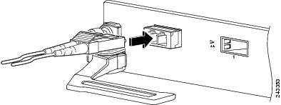 |
About Fiber-Optic Interface Cables
The Ethernet PLIMs use single-mode fiber-optic interface cables to connect to another Ethernet interface, router, or switch. The 10-GE PLIM with 10-GE XENPAK modules and 10-GE DWDM XENPAK modules use cables with SC connectors; the 10-GE WDMPHY PLIM uses cables with LC connectors.
Note |
Fiber-optic cables are not available from Cisco Systems. They can be purchased from cable vendors. |
Single-mode cables are generally yellow in color. You can use two cables with simplex connectors or one cable with dual, keyed connectors.
Warning |
Because invisible radiation may be emitted from the aperture of the port when no fiber cable is connected, avoid exposure to radiation and do not stare into open apertures. Statement 125 |
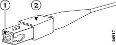
|
1 |
SC cable connector |
2 |
Spring-action disconnect latch |
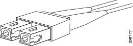
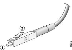
|
1 |
LC connector |
2 |
Spring-action disconnect latch |
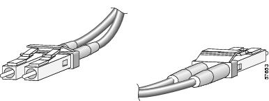
Removing and Installing Fiber-Optic Interface Cables
This section contains information on removing and installing fiber-optic interface cables to connect your router to another router or switch.
Required Tools and Equipment
You need the following tools and part to remove or install interface cables:
- ESD-preventive wrist strap
- Medium (Number 2) Phillips screwdriver
- Interface cables
Removing Fiber-Optic Interface Cables
To remove interface cables, see the following figure and follow these steps:
SUMMARY STEPS
- Attach an ESD-preventive wrist or ankle strap to your wrist and follow its instructions for use.
- Press on the spring-action disconnect latch to disconnect the interface cable connectors from the PLIM interface ports. When the cable is removed from the 10-GE PLIM, the spring-loaded cover plate folds over to cover the interface port. Note that the other PLIMs do not have spring-loaded cover plates that cover their interface ports.
DETAILED STEPS
| Step 1 |
Attach an ESD-preventive wrist or ankle strap to your wrist and follow its instructions for use. |
||||||||||||
| Step 2 |
Press on the spring-action disconnect latch to disconnect the interface cable connectors from the PLIM interface ports. When the cable is removed from the 10-GE PLIM, the spring-loaded cover plate folds over to cover the interface port. Note that the other PLIMs do not have spring-loaded cover plates that cover their interface ports.
|
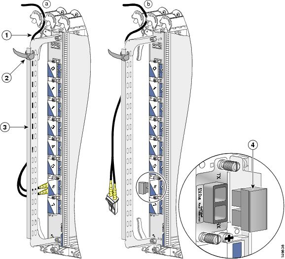
Installing Fiber-Optic Interface Cables
Use two simplex connectors or one duplex connector (see the previous figures).
Note |
Optical fiber cables are available from cable vendors. These cables are not available from Cisco. |
Warning |
Because invisible radiation may be emitted from the aperture of the port when no fiber cable is connected, avoid exposure to radiation and do not stare into open apertures. Statement 125 |
Warning |
Class 1 Laser Product. Statement 1008 |
Note |
Connectors on the fiber-optic cables must be free of dust, oil, or other contaminants. Before connecting the cable to the PLIM, carefully clean the fiber-optic connectors using an alcohol wipe or other suitable cleanser. See the How to Remove or Install a PLIM Cable Management Bracket for more information. |
To install interface cables, follow these steps:
SUMMARY STEPS
- For a 10-GE PLIM, open the spring-loaded plate that covers the port. Note that the other PLIMs do not have spring-loaded cover plates that cover their interface ports. Remove the connector dust cover if one is present.
- Align the connector end of the cable to the appropriate port. Observe the receive (RX) and transmit (TX) cable relationship on the cables, as shown in the following figure.
- Attach a fiber cable between the port in the PLIM and the device to which the PLIM is connected.
- Insert the fiber cable connector until it clicks and locks into place.
- Repeat these steps until all cabling is completed.
DETAILED STEPS
| Step 1 |
For a 10-GE PLIM, open the spring-loaded plate that covers the port. Note that the other PLIMs do not have spring-loaded cover plates that cover their interface ports. Remove the connector dust cover if one is present. |
||||||||
| Step 2 |
Align the connector end of the cable to the appropriate port. Observe the receive (RX) and transmit (TX) cable relationship on the cables, as shown in the following figure. 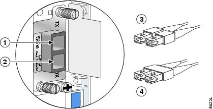
|
||||||||
| Step 3 |
Attach a fiber cable between the port in the PLIM and the device to which the PLIM is connected. |
||||||||
| Step 4 |
Insert the fiber cable connector until it clicks and locks into place. |
||||||||
| Step 5 |
Repeat these steps until all cabling is completed.
|
Cleaning Fiber-Optic Connectors
It is important to inspect and clean fiber-optic components before making a fiber-optic connection (for example, plugging a fiber-optic connector into a fiber-optic receptacle). Any contamination in the fiber connection can cause the optic component or the whole system to fail. Even microscopic dust particles, oil from human hands, film residues (condensed from vapors in the air), and powdery coatings (left after water or other solvents evaporate) can cause a variety of problems for optical connections.
Caution |
With the high-powered lasers now in use, any contaminant can be burned into the fiber end face if it blocks the core while the laser is turned on. This burning may damage the optical surface enough that it cannot be cleaned. |
For instructions on how to clean fiber-optic components, see:
http://www.cisco.com/warp/public/127/cleanfiber2.html
Always follow the fiber-optic cleaning procedures carefully. The goal is to eliminate any dust or contamination and provide a clean environment for the fiber-optic connection. Inspection, cleaning, and reinspection are critical steps that must be performed before making any fiber-optic connection.
How to Remove or Install a XENPAK Optics Module
The 10-GE XENPAK PLIMs support the DWDM XENPAK optics modules listed in PLIM Descriptions and Software and Hardware Compatibility. These optics modules are installed in ports on the PLIM and provide the optical interface connectors for the PLIM.
Note |
XENPAK optics modules are keyed so that they cannot be inserted incorrectly. The PLIM automatically shuts down any optics module that is not a valid type. |
The following figure shows a DWDM XENPAK optics module.
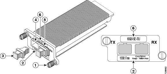
|
1 |
Captive installation screws |
4 |
Transmit (TX) optical bore |
|
2 |
Center wavelength warning label |
5 |
Receive (RX) optical bore |
|
3 |
Dust plug |
6 |
XENPAK module label |
This section contains the following procedures:
Prerequisites
To stay within the maximum received power specification on the RX side of the XENPAK module, an attenuator might be required. To determine if an attenuator is needed for the XENPAK module, see Specifications for 10-GE XENPAK Interfaces section.
Required Tools and Equipment
Have the following equipment available before you install or remove a XENPAK module:
- Dust plugs to keep unused ports clean
- Antistatic surface on which to place the module
- Attenuator, if one is determined to be needed in the prerequisites
Removing a XENPAK Optics Module
This section describes how to remove a XENPAK optics module from the PLIM.
SUMMARY STEPS
- Use the shutdown command before you remove a XENPAK optics module.
- Disconnect any network interface cables that are attached to the optics module, and install the optical bore dust plugs.
- Loosen the two captive screws securing the optics module in the PLIM.
- Carefully pull the two captive screws to disconnect the optics module from the connector within the PLIM port.
- Grasp the edges of the optics module, and carefully slide it from the PLIM port.
- Place the optics module on an antistatic surface.
DETAILED STEPS
| Step 1 |
Use the shutdown command before you remove a XENPAK optics module.
|
||
| Step 2 |
Disconnect any network interface cables that are attached to the optics module, and install the optical bore dust plugs. |
||
| Step 3 |
Loosen the two captive screws securing the optics module in the PLIM. |
||
| Step 4 |
Carefully pull the two captive screws to disconnect the optics module from the connector within the PLIM port. |
||
| Step 5 |
Grasp the edges of the optics module, and carefully slide it from the PLIM port. |
||
| Step 6 |
Place the optics module on an antistatic surface. |
Installing a XENPAK Optics Module
This section describes how to install a XENPAK optics module in the PLIM.
SUMMARY STEPS
- Remove the optics module from its protective packaging.
- Align the optics module with the PLIM port, and slide the module into the port until the back of the optics module faceplate is flush with the PLIM faceplate. This step ensures proper connection between the PLIM connector and the optics module connector. XENPAK modules are keyed so that they cannot be inserted incorrectly.
- Secure the optics module by tightening the two captive installation screws. Do not cross-thread or overtighten the captive screws.
- Remove the optical bore dust plugs from the optics module, and attach the network interface cable to the optics module connector.
DETAILED STEPS
| Step 1 |
Remove the optics module from its protective packaging. |
||
| Step 2 |
Align the optics module with the PLIM port, and slide the module into the port until the back of the optics module faceplate is flush with the PLIM faceplate. This step ensures proper connection between the PLIM connector and the optics module connector. XENPAK modules are keyed so that they cannot be inserted incorrectly. |
||
| Step 3 |
Secure the optics module by tightening the two captive installation screws. Do not cross-thread or overtighten the captive screws.
|
||
| Step 4 |
Remove the optical bore dust plugs from the optics module, and attach the network interface cable to the optics module connector. |
How to Remove or Install an XFP Module
The 10-GE XFP PLIMs support the XFP optics modules listed in PLIM Descriptions and Software and Hardware Compatibility. The 10-GE XFP transceiver module is a hot-swappable I/O device that plugs into 10-GE ports (see the following figure). The XFP transceiver module connects the electrical circuitry of the system with the optical network.
Note |
The dual LC connector on the XFP transceiver modules supports network interface cables with either Physical Contact (PC) or Ultra-Physical Contact (UPC) polished face types. The dual LC connector on the XFP transceiver modules does not support network interface cables with an Angle Polished Connector (APC) polished face type. |
Caution |
We strongly recommended that you do not install or remove the XFP module with fiber-optic cables attached to it because of the potential of damaging the cable, the cable connector, or the optical interfaces in the XFP module. Disconnect all cables before removing or installing an XFP module.Removing and inserting an XFP module can shorten its useful life, so you should not remove and insert XFP modules more often than what is absolutely necessary. |
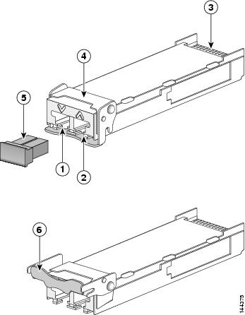
|
1 |
Transmit optical bore |
2 |
Receive optical bore |
3 |
Transceiver socket connector |
|
4 |
Bail clasp (locked position) |
5 |
Dust plug |
6 |
Bail clasp (unlocked position) |
Installing a 10-GE XFP Transceiver Module
Caution |
The XFP transceiver is a static-sensitive device. Always use an ESD wrist strap or similar individual grounding device when handling XFP transceivers or coming into contact with system modules. |
To install an XFP transceiver, follow these steps:
SUMMARY STEPS
- Remove the XFP transceiver from its protective packaging.
- Check the label on the XFP transceiver body to verify that you have the correct model for your network.
- Position the XFP transceiver in front of the XFP socket opening on the module. Slide the XFP transceiver part of the way into the transceiver socket on the system module front panel.
- Remove the optical bore dust plug from the XFP transceiver.
- Pivot the bail clasp up so that it is parallel with the transceiver body (see the following figure).
- Continue sliding the XFP transceiver into the socket until the XFP transceiver is mated with the transceiver socket connector.
- Latch the XFP transceiver in the transceiver socket by pivoting the bail clasp down so that the bail clasp is perpendicular to the transceiver body (see the following figure).
- Immediately reinstall the dust plug in the XFP transceiver optical bores. Do not remove the dust plug until you are ready to attach the network interface cable.
DETAILED STEPS
| Step 1 |
Remove the XFP transceiver from its protective packaging. |
||
| Step 2 |
Check the label on the XFP transceiver body to verify that you have the correct model for your network. |
||
| Step 3 |
Position the XFP transceiver in front of the XFP socket opening on the module. Slide the XFP transceiver part of the way into the transceiver socket on the system module front panel. |
||
| Step 4 |
Remove the optical bore dust plug from the XFP transceiver. |
||
| Step 5 |
Pivot the bail clasp up so that it is parallel with the transceiver body (see the following figure). |
||
| Step 6 |
Continue sliding the XFP transceiver into the socket until the XFP transceiver is mated with the transceiver socket connector. |
||
| Step 7 |
Latch the XFP transceiver in the transceiver socket by pivoting the bail clasp down so that the bail clasp is perpendicular to the transceiver body (see the following figure).
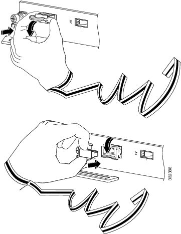 |
||
| Step 8 |
Immediately reinstall the dust plug in the XFP transceiver optical bores. Do not remove the dust plug until you are ready to attach the network interface cable.
|
Removing a 10-GE XFP Transceiver Module
Caution |
The XFP transceiver is a static-sensitive device. Always use an ESD wrist strap or similar individual grounding device when handling XFP transceivers or coming into contact with modules. |
If you are removing an XFP transceiver, follow these steps:
SUMMARY STEPS
- Disconnect the network interface cable from the XFP transceiver connectors.
- Pivot the XFP transceiver bail clasp up to release the XFP transceiver from the socket (see the following figure).
- Slide the XFP transceiver out of the socket. Pivot the bail clasp down and immediately install the dust plug in the XFP transceiver optical bores (see the following figure).
- Immediately place the XFP transceiver in an antistatic bag.
DETAILED STEPS
| Step 1 |
Disconnect the network interface cable from the XFP transceiver connectors. |
| Step 2 |
Pivot the XFP transceiver bail clasp up to release the XFP transceiver from the socket (see the following figure). |
| Step 3 |
Slide the XFP transceiver out of the socket. Pivot the bail clasp down and immediately install the dust plug in the XFP transceiver optical bores (see the following figure). |
| Step 4 |
Immediately place the XFP transceiver in an antistatic bag. 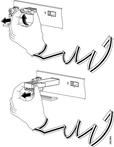 |
40-GE PLIMs
This section provides information specific to the following 40-GE PLIMs:
The CFP Transceiver Module supported for the 2-port and 4-port PLIMs is described in the following section: 40-GE Ethernet CFP Transceiver Module.
2-Port 40-GE OTU3 PLIM with CFP Optics Module
The 2-port 40-GE OTU3 PLIM supports up to 2 40-GE C Form-factor Pluggable (CFP) optics modules.
Supported CFP Optical Transceiver Modules
-
CFP-40G-LR4
-
CFP-40G-FR
-
CFP-40G-SR4
Note |
SR4 optics do not support OTN. |
Cisco qualifies the optics that are approved for use with its PLIMs.
Ports and LEDs
The 2-port 40-GE OTU3 CFP PLIM has:
- Two ports that accept CFP optics modules
- Status LED for the PLIM
- One LED indicator for each port
The following figure shows the front panel of the 2-port 40-GE OTU3 CFP PLIMs.
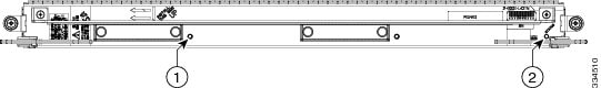
|
1 |
Port LED (one per port) |
2 |
Status LED |
The following table describes the PLIM LEDs for the 2-port 40-GE OTU3 CFP PLIM.
|
LED |
State |
Description |
|---|---|---|
|
Status |
Green |
PLIM is powered on and operating correctly. |
|
Yellow |
PLIM is powered on but is initializing. |
|
|
Off |
PLIM is powered off or power on did not complete successfully. |
|
|
Port |
Green |
Port is enabled by software and there is a valid link. |
|
Yellow |
The port is enabled by software, but there is a problem with the link. |
|
|
Off |
Port is not enabled by software or the PLIM is powered off. |
Physical Characteristics
- Height—20.6 in (52.2 cm)
- Depth—11.2 in (28.4 cm)
- Width—1.8 in (4.49 cm)
- Weight—9.45 lb (4.27 kg)
- Power consumption—160 W
40-GE Ethernet CFP Transceiver Module
The 4-port 40-GE OTU3 PLIM supports up to 4 40-GE C Form-factor Pluggable (CFP) optics modules. The 4-port 40-GE OTU3 CFP PLIM is a high-powered PLIM.
Power Management Restrictions
Note |
The following restrictions apply only to the legacy 16-slot chassis. |
Cisco CRS high-powered PLIMs are subject to slot placement restrictions on the legacy 16-slot chassis. The following error message appears if these restrictions are not followed:
PLATFORM-SHELFMGRV2-4-HIGH_POWERED_PLIM_NOT_POWERED_ON_IN_LOWER_BAY
The following PLIMs are high-powered PLIMs:
- CRS-CGSE-PLIM—Cisco CRS Carrier Grade Services Engine (CGSE) PLIM
- 1OC768-DPSK/C-O—Cisco CRS-1 1xOC768 (C-band) DPSK+ DWDM PLIM (Offset TDC)
- 6-10GE-WLO-FLEX—Cisco CRS Flexible PLIM
- 4-40GE-L/OTN—Cisco CRS 4-Port 40 GE LAN/OTN Interface Module
The rules for placement of high-powered PLIMs are:
- A FLEX PLIM (6-10GE-WLO-FLEX) in the lower shelf cannot be placed under a CGSE PLIM directly above in the upper shelf.
- High-powered PLIMs may only be placed in lower slots if a high-powered PLIM is in the slot directly above or if the slot above is empty.
Supported CFP Optical Transceiver Modules
-
CFP-40G-LR4
-
CFP-40G-FR
-
CFP-40G-SR4
Note |
SR4 optics do not support OTN. |
Cisco qualifies the optics that are approved for use with its PLIMs.
Ports and LEDs
The 4-port 40-GE OTU3 CFP PLIM has:
- Four ports that accept CFP optics modules
- Status LED for the PLIM
- One LED indicator for each port
The following figure shows the front panel of the 4-port 40-GE OTU3 CFP PLIMs.
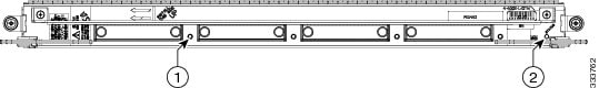
|
1 |
Port LED (one per port) |
2 |
Status LED |
The following table describes the PLIM LEDs for the 4-port 40-GE OTU3 CFP PLIM.
|
LED |
State |
Description |
|---|---|---|
|
Status |
Green |
PLIM is powered on and operating correctly. |
|
Yellow |
PLIM is powered on but is initializing. |
|
|
Off |
PLIM is powered off or power on did not complete successfully. |
|
|
Port |
Green |
Port is enabled by software and there is a valid link. |
|
Yellow |
The port is enabled by software, but there is a problem with the link. |
|
|
Off |
Port is not enabled by software or the PLIM is powered off. |
Physical Characteristics
- Height—20.6 in (52.2 cm)
- Depth—11.2 in (28.4 cm)
- Width—1.8 in (4.49 cm)
- Weight—11.769 lb (5.34 kg)
- Power consumption—185 W
Oversubscription of 40-GE Ports
Processing on the 4-port 40-GE OTU3 CFP PLIM is performed by two PLIM hardware controllers, each of which can process up to 80 Gbps of traffic. Ports 0 and 1 are associated with one PLIM hardware controller, while ports 2 and 3 are associated with the second PLIM hardware controller. In addition, the PLIM ports are serviced by line card hardware controllers that have a total switching capacity of 140 Gbps.
Because of this PLIM design, maximum throughput on the 4-port 40-GE OTU3 CFP PLIM is limited to 140 Gbps evenly distributed across the four ports. A second limitation exists, this time at the individual PLIM hardware controller level. For certain packet sizes, the effective bandwidth of the PLIM hardware controller can drop to as low as 73 Gbps (maximum 80 Gbps), which is distributed evenly to it's 2 connected ports (36.5 Gbps per port). Effective bandwidth of the PLIM hardware controller usually drops below 80Gbps at smaller packet sizes (traffic streams that contain a relatively high proportion of packets sized below 128 bytes).
40-GE Ethernet CFP Transceiver Module
The 40-GE CFP transceiver module is a hot-swappable I/O device that plugs into 40-GE ports. The CFP transceiver module connects the electrical circuitry of the system with the optical network.
Caution |
If no CFP optics module is to be installed in a port, the open port must be covered with a CFP-COVER (shipped with the card). The CFP-COVER is required under this condition to preserve the integrity of the card and is required for EMC and Safety compliance and proper cooling in the chassis. |
Note |
Review the safety information and guidelines before installing or removing a CFP transceiver module. See How to Remove or Install a PLIM. |
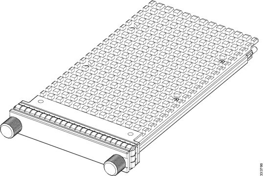
Note |
CFP Module Port Cabling Specifications provides cabling specifications for the CFP modules that can be installed on the 2- or 4-port 40-GE OTU3 CFP PLIM.
|
Part Number |
Wavelength (nm) |
Fiber Type |
Connector Type |
Typical Maximum Distance |
|---|---|---|---|---|
|
CFP-40G-LR4 |
1271129113111331 |
SMF |
SC |
10 km |
|
CFP-40G-FR |
1547.5 |
SMF |
SC |
2 km |
|
CFP-40G-SR4 |
850 |
MMF |
MPO (Multipath Optical) |
100 m |
100-GE PLIMs
This section provides information specific to the following 100-GE PLIMs:
1-Port 100-GE PLIM with C FP Optics Module
The 1-port 100-GE CFP PLIM supports a single 100-GE C Form-factor Pluggable (CFP) optics module.
Supported CFP Optical Transceiver Modules
- CFP-100GE-LR4, V01
- CFP-100G-SR10
Cisco qualifies the optics that are approved for use with its PLIMs.
For the modules listed, use a single-mode optical fiber that has a modal-field diameter of 8.7 ±0.5 microns (nominal diameter is approximately 10/125 micron) to connect your router to a network.
For more details, see 100-GE Ethernet CFP Transceiver Module.
Ports and LEDs
The 1-port 100-GE CFP PLIM has:
- One port that accepts a CFP optics module
- Status LED for the PLIM
- Four LED indicators for the single port
The following figure shows the front panel of the 1-Port 100-GE CFP PLIMs.

|
1 |
Active LED |
2 |
Link LED |
3 |
Tx PKT LED |
4 |
Rx PKT LED |
5 |
Status LED |
The following table describes the PLIM LEDs for the 1-Port 100-GE CFP PLIM.
|
LED |
State |
Description |
|---|---|---|
|
PLIM Status |
Green |
PLIM is properly seated and operating correctly. |
|
Yellow |
PLIM is powered on, but initializing. |
|
|
Off |
PLIM is not properly seated, system power is off, or power up did not complete successfully. |
|
|
Active |
Green |
Port is enabled by software and there is a valid link. |
|
Yellow |
Port is enabled by software, but there is a problem with the link. |
|
|
Off |
Port is not enabled by software. |
|
|
Link |
Green |
Valid link is achieved. |
|
Off |
Valid link is not achieved. |
|
|
Tx PKT |
Green (flashing) |
Packets are being transmitted on the port. |
|
Off |
No packets are being transmitted on the port. |
|
|
Rx PKT |
Green (flashing) |
Packets are being received on the port. |
|
Off |
No packets are being received on the port. |
Physical Characteristics
- Height—20.6 in (52.2 cm)
- Depth—11.2 in (28.4 cm)
- Width—1.8 in (4.49 cm)
- Weight—7.17 lbs (3.24 kg)
- Power consumption—150 W
100-GE Ethernet CFP Transceiver Module
The 100-GE CFP transceiver module is a hot-swappable I/O device that plugs into 100-GE ports (see the following figure). The CFP transceiver module connects the electrical circuitry of the system with the optical network.
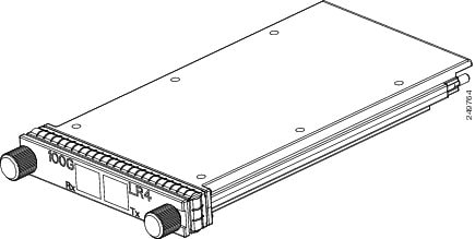
The CFP uses duplex single mode SC fiber cabling. The following table provides cabling specifications for the CFP modules that can be installed on the 1-Port 100-GE CFP PLIM.
Caution |
A CFP optics module must be installed in the CFP transceiver module slot of each 100GE PLIM installed in the Cisco CRS chassis. The CFP transceiver module preserves the integrity of the card and is required for EMI and Safety compliance and proper cooling in the chassis. |
Note |
Review the safety information and guidelines before installing or removing a CFP transceiver module. See How to Remove or Install a PLIM. |
|
Part Number |
Description |
Wavelength (nm) |
Fiber Type |
Typical Maximum Distance |
|---|---|---|---|---|
|
CFP-100GE-LR4, V01 |
100-GE pluggable optical transceiver modules |
1295.561300.0551304.5851309.14 |
SMF |
6.213 miles (10 km) |
|
CFP-100G-SR10 |
100 GE over 10 short-reach optical lanes (SR10) optics (multimode fiber) |
1295.561300.0551304.5851309.14 |
MMF |
100 m |
1-Port 100-GE PLIM with IP over DWDM
The 1-port 100-GE DWDM PLIM supports the IP over DWDM optics module. The 1-port 100-GE IP over DWDM PLIM is a thermally-sensitive PLIM. When used at high altitudes, it should be placed in the lower card cage.
Thermal Restrictions
Note |
The following restrictions apply only to the legacy 16-slot chassis. |
Cisco CRS thermally-sensitive PLIMs are subject to slot placement restrictions on the legacy 16-slot chassis. The following error message appears if these restrictions are not followed:
PLATFORM-SHELFMGRV2-4-AVOID_THERMALLY_SENSITIVE_PLIM_IN_UPPER_SLOT
The thermally-sensitive PLIM limitation is due to the possibility of some components exceeding their rated temperature tolerance when the system is run at 50C at elevations of 1800 meters or higher. If the high temperature condition occurs, the environmental monitoring software will shut down the thermally-sensitive PLIM when its temperature reaches configured thresholds. Therefore, this restriction applies only to routers operating at these high elevations and may be ignored otherwise.
Ports and LEDs
The 1-port 100-GE IP over DWDM PLIM has:
- One port that accepts a DWDM optics module that is not pluggable
- Status LED for the PLIM
- One LED indicator for the single port
Cisco qualifies the optics that are approved for use with its PLIMs.
The following figure shows the front panel of the 1-port 100-GE IP over DWDM PLIMs.
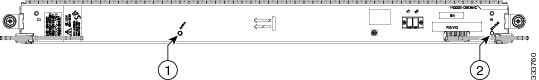
|
1 |
Port LED |
2 |
Status LED |
|
LED |
State |
Description |
|---|---|---|
|
Status |
Green |
PLIM is powered on and operating correctly. |
|
Yellow |
PLIM is powered on but is initializing. |
|
|
Off |
PLIM is powered off or power up did not complete successfully. |
|
|
Port |
Green |
Port is enabled by software and there is a valid link. |
|
Yellow |
Port is enabled by software, but there is a problem with the link. |
|
|
Off |
Port is not enabled by software. |
Physical Characteristics
- Height—20.6 in (52.2 cm)
- Depth—11.2 in (28.4 cm)
- Width—1.8 in (4.49 cm)
- Weight—8.325 lb (3.78 kg)
- Power consumption—195 W
4-Port 100-GE PLIM with CPAK Optics Module
Note |
In the enhanced chassis, all 4 ports of this PLIM can be used. In the legacy chassis, this PLIM is operated in 200G mode as a 2-port 100-GE CPAK PLIM. In this case, only the lower 2 ports are enabled. |
The 4-port 100-GE CPAK PLIM supports the CPAK optics module.
Ports and LEDs
The 4-port 100-GE CPAK PLIM has:
-
Four ports that accept CPAK optics modules
-
Status LED for the PLIM
-
One LED indicator for the single port
Cisco qualifies the optics that are approved for use with its PLIMs.
The following figure shows the front panel of the 4-port 100-GE CPAK PLIMs.

|
1 |
Port LED |
2 |
Status LED |
The 4-Port 100-GE PLIM comprises two sets of two ports, each of which are connected to a dedicated Network Processor. When operated in the legacy chassis, the PLIM operates in 200G mode, in which the top set of ports and their Network Processor are deactivated due to thermal constraints. In 200G mode, the port numbering will be different than 400G mode and will start with 0 for the port that is labeled 2 in 400G mode. The faceplate labels therefore include two port numbers for the ports that are active in 200G Mode, as shown in the following figure.
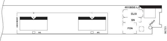
In the enhanced chassis, the 4-Port 10-GE PLIM may optionally operate in Green mode, in which two of the ports are deactivated (using the CLI) to save power. In Green mode, the port numbering follows the 400G mode model, which results in only ports 1-2 being active. Ports 0-1 will not be visible in the CLI when the card is in Green mode. Therefore, the port numbers for ports used in Green mode will not change when the card is converted to 400G mode.
The following table describes the PLIM LEDs for the 4-port 100-GE CPAK PLIM.
|
LED |
State |
Description |
|---|---|---|
|
Status |
Green |
PLIM is powered on and operating correctly. |
|
Yellow |
PLIM is powered on but is initializing. |
|
|
Off |
PLIM is powered off or power up did not complete successfully. |
|
|
Port |
Green |
Port is enabled by software and there is a valid link. |
|
Yellow |
Port is enabled by software, but there is a problem with the link. |
|
|
Off |
Port is not enabled by software. |
Physical Characteristics
-
Height—20.6 in (52.2 cm)
-
Depth—11.2 in (28.4 cm)
-
Width—1.8 in (4.49 cm)
-
Weight—8.6 lbs (3.9 kg)
-
Power consumption—120 W
CPAK Optical Module
A CPAK optical module is a pluggable optical transceiver module that can be installed on a line card. CPAK modules supported on 4-Port 100-GE PLIM are:
-
Cisco CPAK 100GBASE-LR4 module, which supports link lengths of up to 10 km over standard single-mode fiber (SMF). Supports high-bandwidth 100 Gbps optical links over SMF terminated with SC connectors.
-
Cisco CPAK 100GBASE-SR10 module, which supports link lengths of up to 100 m and 150 m on laser-optimized OM3 and OM4 multifiber cables, respectively. Delivers high-bandwidth 100 Gbps links over 24-fiber ribbon cables terminated with MPO/MTP connectors. Can also be used in 10x10 Gb mode along with ribbon-to-duplex-fiber breakout cables for connectivity to ten 10GBASE-SR optical interfaces.
-
Cisco CPAK-100G-SR4 is specified to run only at 100GE LAN and does not support OTU4.
-
Cisco CPAK-100G-CWDM4, which supports link lengths of up to 2 km over a standard pair of G.652 single-mode fiber (SMF) with duplex LC connectors. The 100 Gigabit Ethernet signal is carried over four wavelengths. Multiplexing and demultiplexing of the four wavelengths are managed within the device.
|
Product |
Type |
Transmit Power (dBm) Transmitter and receiver power are in averages, unless specified. |
Receive Power (dBm) Transmitter and receiver power are in averages, unless specified. |
Transmit and Receive Center Wavelength Range (nm) |
|---|---|---|---|---|
|
CPAK-100G-LR4 |
100GBASE-LR4 1310 nm SMF |
Maximum: 4.5 per lane Minimum: -4.3 per lane |
Maximum: 4.5 per lane Minimum: -10.6 per lane |
Four lanes: 1294.53 to 1296.59 1299.02 to 1301.09 1303.54 to 1305.63 1308.09 to 1310.19 |
|
CPAK-100G-SR10 |
100GBASE-SR10 850 nm MMF |
Maximum: -1.0 per lane Minimum: -7.6 per lane |
Maximum: 2.4 per lane Minimum: -9.5 per lane |
Ten lanes: 850 to 860 |
|
CPAK-100G-SR4 |
100GBASE-SR4 850 nm MMF |
Max: 2.4 per lane Min: -8.4 per lane |
Max: 2.4 per lane Min: -10.3 per lane |
Four lanes: 840 to 860 |
|
CPAK-100G-CWDM4 |
100GBASE CWDM4 SMF |
Max: +2.5, per lane Min: -6.5, per lane |
Max: +2.5, per lane Min: -10, per lane |
Four lanes: 1271, 1291, 1311, 1331 |
CPAK Module Cabling and Connection Equipment
The following table provides cabling specifications for the CPAK modules that can be installed on the 4-port 100-GE CPAK PLIM.
The optical patch cord uses connectors that can be plugged into the CPAK modules. They are:
-
CPAK-100G-LR4 module: Dual SC/PC connector.
-
CPAK-100G-SR10: 24-fiber MPO/MTP connector (female).
-
CPAK-100G-SR4: 12-fiber MPO/MTP connector (female).
-
CPAK-100G-CWDM4: Dual LC connector.
The minimum cable distance for the CPAK-100G-LR4 is 6.5 feet (2 m).
|
CPAK Modules |
Wavelength (nm) |
Cable Type |
Core Size (micron) |
Modal Bandwidth (MHz*km) 2 |
Cable Distance 3 |
|---|---|---|---|---|---|
|
CPAK-100G-LR4 |
1310 |
SMF |
9 micron core SMF per G.652 |
— |
6.2 miles (10 km) |
|
CPAK-100G-SR10 |
850 |
MMF |
50.0 50.0 |
2000 (OM3) 4700 (OM4) |
100 m 150 m4 |
|
CPAK-100G-SR4 |
850 |
MMF (12 fibers) |
50.0 50.0 |
2000 (OM3) 4700 (OM4) |
70 m 100 m 5 |
|
CPAK-100G-CWDM4 |
1271, 1291, 1311, 1331 |
SMF Duplex |
9-micron core SMF per G.652 |
— |
2 km |
Combination PLIMs
This section provides information specific to the following combination PLIM:
The following sections provide information about the transceiver modules supported on the combination PLIM:
2-port 100-GE and 5-port 40-GE QSFP+ Combination PLIM
The 2-port 100-GE and 5-port 40-GE QSFP+ combination PLIM supports up to 2 CPAK optics modules and up to 5 40-Gigabit Quad Small Form-Factor Pluggable Plus (QSFP+) optics modules.
Supported CPAK Optics Modules
-
CPAK-100G-LR4
-
CPAK-100G-SR10
-
CPAK-100G-CWDM4
Supported QSFP+ Optics Modules
-
QSFP-40G-SR4
-
QSFP-40GE-LR4
-
QSFP-40G-LR4
Ports and LEDs
The 2-port 100-GE and 5-port 40-GE QSFP+ combination PLIM has:
-
Two ports that accept CPAK optics modules
-
Five ports that accept QSFP+ optics modules
-
Status LED for the PLIM
-
One LED indicator for each port
Cisco qualifies the optics that are approved for use with its PLIMs.
The following figure shows the front panel of the 2-port 100-GE and 5-port 40-GE QSFP+ combination PLIM.
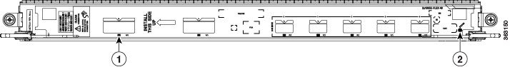
|
1 |
Port LED |
2 |
Status LED |
The 2-port 100-GE and 5-port 40-GE QSFP+ combination PLIM comprises two sets of two ports, each of which are connected to a dedicated Network Processor. When operated in the legacy chassis, the PLIM operates in 200G mode, in which the two 100G CPAK ports are deactivated and only the 40G QSFP+ ports are activated. When operated in the enhanced chassis, the PLIM operates in 400G mode, in which all ports (2x100GE ports and 5x40GE ports) are activated. Switching from 400G mode to 200G mode in the enhanced chassis is not supported.
Note |
For 40-Gbps to 10-Gbps breakout options, the 40-GE ports only support the SR-4 breakout cable that has a cylindrical splitter. |
In 200G mode, the port numbering is different than 400G mode and starts with 0 for the port that is labeled 2 in 400G mode. The faceplate labels therefore include two port numbers for the ports that are active in 200G Mode, as shown in the following figure.
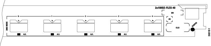
The following table describes the PLIM LEDs for the 2-port 100-GE and 5-port 40-GE QSFP+ combination PLIM.
|
LED |
State |
Description |
|---|---|---|
|
Status |
Green |
PLIM is powered on and operating correctly. |
|
Yellow |
PLIM is powered on but is initializing. |
|
|
Off |
PLIM is powered off or power up did not complete successfully. |
|
|
Port |
Green |
Port is enabled by software and there is a valid link. |
|
Yellow |
PLIM is powered on but port is not enabled by software. |
|
|
Off |
PLIM is powered off. |
Physical Characteristics
- Height—20.6 in (52.2 cm)
- Depth—11.2 in (28.4 cm)
- Width—1.8 in (4.49 cm)
- Weight—8.18 lbs (4.0 kg)
- Power consumption—140 W
40-Gigabit QSFP+ Transceiver Module
The 40-Gigabit QSFP+ transceiver module is a hot-swappable, parallel fiber-optical module with four independent optical transmit and receive channels. The QSFP+ transceiver module connects the electrical circuitry of the system with an optical external network. The following figure shows the optical QSFP+ transceiver. The transceiver is used primarily in short reach applications in switches, routers, and data center equipment where it provides higher density than SFP+ modules.
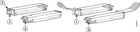
|
1 |
40GBASE QSFP+ transceiver body |
|
2 |
Bail-clasp latch |
|
3 |
Electrical connection to the module circuitry |
The following table lists the different 40-Gigabit QSFP+ transceiver module types.
|
QSFP+ Transceiver Module Product Number |
Description |
|---|---|
|
QSFP-40G-SR4 |
Cisco 40GBASE-SR4 QSFP+ transceiver module for MMF, multi-fiber MPO connector |
|
QSFP-40G-LR4 |
Cisco 40GBASE-LR4 QSFP+ transceiver module for SMF, duplex LC connector, multi-rate with OTU3 support |
|
QSFP-40GE-LR4 |
Cisco 40GBASE-LR4 QSFP+ transceiver module for SMF, duplex LC connector, 40G Ethernet rate only |
Note |
The multiple-fiber push-on (MPO) connectors on the optical QSFP+ transceivers support network interface cables with either Physical contact (PC) or Ultra-Physical Contact (UPC) flat-polished face types. The MPO connectors on the optical QSFP+ transceivers do not support network interface cables with an angle-polished contact (APC) face type. |
The following table lists the 40-Gigabit optical QSFP+ port cabling specifications.
|
QSFP+ Product Number |
Nominal Wavelength (nm) |
Cable Type |
Core Size (microns) |
Modal Bandwidth (MHz/km) |
Maximum Cabling Distance |
|---|---|---|---|---|---|
|
QSFP-40G-SR4= |
850 |
MMF |
50.0 50.0 |
20004700 |
100 m (328 ft) 150 m (492 ft) |
|
QSFP-40G-LR4= |
1271,1291,13111331 |
SMF |
G.652 |
- |
10km |
|
QSFP-40GE-LR4= |
1271,1291,13111331 |
SMF |
G.652 |
- |
10 km |
The following table lists the QSFP+ transceiver modules optical transmit and receive specifications.
|
QSFP+ Product Number |
Transceiver Operating Mode |
Transmit Power (dBm) |
Receive Power (dBm) |
Transmit and Receive Wavelength (nm) |
|---|---|---|---|---|
|
QSFP-40G-SR4= |
40GBASE-SR4, 4 lanes, 850 nm |
1 per lane (Max) –7.6 per lane (Min) |
2.4 per lane (Max) –9.5 per lane (Min) |
850 nm on each lane |
|
QSFP-40G-LR4= |
40GBASE-LR4 and OTU3 |
2.3 per lane (Max) –7 per lane (Min) |
2.3 per lane (Max) –13.7 per lane (Min) |
Four wavelengths1271,1291,13111331 |
|
QSFP-40GE-LR4= |
40GBASE-LR4 |
2.3 per lane (Max) –7 per lane (Min) |
2.3 per lane (Max) –13.7 per lane (Min) |
Four wavelengths1271,1291,13111331 |
Installing the 40-Gigabit QSFP+ Transceiver Module
The QSFP+ transceiver module can have either a bail-clasp latch or a pull-tab latch. Installation procedures for both types of latches are provided.
Caution |
The QSFP+ transceiver module is a static-sensitive device. Always use an ESD wrist strap or similar individual grounding device when handling QSFP+ transceiver modules or coming into contact with system modules. |
To install an QSFP+ transceiver module, follow these steps:
SUMMARY STEPS
- Attach an ESD wrist strap to yourself and a properly grounded point on the chassis or the rack.
- Remove the QSFP+ transceiver module from its protective packaging.
- Check the label on the QSFP+ transceiver module body to verify that you have the correct model for your network.
- For optical QSFP+ transceivers, remove the optical bore dust plug and set it aside.
- For transceivers equipped with a bail-clasp latch:
- For QSFP+ transceivers equipped with a pull-tab:
- Press firmly on the front of the QSFP+ transceiver with your thumb to fully seat the transceiver in the module’s transceiver socket. (See the following figure.)
- For optical QSFP+ modules, reinstall the dust plug into the QSFP+ transceivers optical bore until you are ready to attach the network interface cable. Do not remove the dust plug until you are ready to attach the network interface cable.
DETAILED STEPS
| Step 1 |
Attach an ESD wrist strap to yourself and a properly grounded point on the chassis or the rack. |
||
| Step 2 |
Remove the QSFP+ transceiver module from its protective packaging. |
||
| Step 3 |
Check the label on the QSFP+ transceiver module body to verify that you have the correct model for your network. |
||
| Step 4 |
For optical QSFP+ transceivers, remove the optical bore dust plug and set it aside. |
||
| Step 5 |
For transceivers equipped with a bail-clasp latch:
|
||
| Step 6 |
For QSFP+ transceivers equipped with a pull-tab:
|
||
| Step 7 |
Press firmly on the front of the QSFP+ transceiver with your thumb to fully seat the transceiver in the module’s transceiver socket. (See the following figure.)
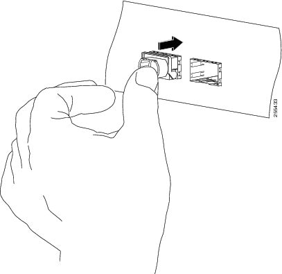 |
||
| Step 8 |
For optical QSFP+ modules, reinstall the dust plug into the QSFP+ transceivers optical bore until you are ready to attach the network interface cable. Do not remove the dust plug until you are ready to attach the network interface cable. |
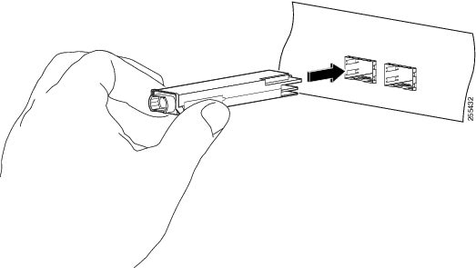
Attaching the Optical Network Cable
Before removing the dust plugs and making any optical connections, follow these guidelines:
-
- Keep the protective dust plugs installed in the unplugged fiber-optic cable connectors and in the transceiver optical bores until you are ready to make a connection.
- Inspect and clean the MPO connector end faces just before you make any connections. See the Tip following step 2 in the next procedure for a pointer to a fiber-optic inspection and cleaning document.
- Grasp the MPO connector only by the housing to plug or unplug a fiber-optic cable.
Note |
40-Gigabit QSFP+ transceiver modules are keyed to prevent incorrect insertion. |
Note |
The multiple-fiber push-on (MPO) connectors on the optical QSFP+ transceivers support network interface cables with either physical contact (PC) or ultra-physical contact (UPC) flat polished face types. The MPO connectors on the optical QSFP+ transceivers do not support network interface cables with an angle-polished contact (APC) face type. |
SUMMARY STEPS
- Remove the dust plugs from the optical network interface cable MPO connectors. Save the dust plugs for future use.
- Inspect and clean the MPO connector’s fiber-optic end faces. See the Tip below for a pointer to a fiber-optic inspection and cleaning document.
- Remove the dust plugs from the QSFP+ transceiver module optical bores.
- Immediately attach the network interface cable MPO connectors to the QSFP+ transceiver module.
DETAILED STEPS
| Step 1 |
Remove the dust plugs from the optical network interface cable MPO connectors. Save the dust plugs for future use. |
||
| Step 2 |
Inspect and clean the MPO connector’s fiber-optic end faces. See the Tip below for a pointer to a fiber-optic inspection and cleaning document.
|
||
| Step 3 |
Remove the dust plugs from the QSFP+ transceiver module optical bores. |
||
| Step 4 |
Immediately attach the network interface cable MPO connectors to the QSFP+ transceiver module. |
Removing the 40-Gigabit QSFP+ Transceiver Module
Caution |
The QSFP+ transceiver module is a static-sensitive device. Always use an ESD wrist strap or similar individual grounding device when handling QSFP+ transceiver modules or coming into contact with modules. |
To remove a QSFP+ transceiver, follow these steps:
SUMMARY STEPS
- For optical QSFP+ transceivers, disconnect the network interface cable from the QSFP+ transceiver connector.
- For QSFP+ transceivers equipped with a bail-clasp latch (See see the following figure, top view):
- For QSFP+ transceivers equipped with a pull tab latch (See the following figure, bottom view):
- Place the QSFP+ transceiver into an antistatic bag.
DETAILED STEPS
| Step 1 |
For optical QSFP+ transceivers, disconnect the network interface cable from the QSFP+ transceiver connector. |
| Step 2 |
For QSFP+ transceivers equipped with a bail-clasp latch (See see the following figure, top view):
|
| Step 3 |
For QSFP+ transceivers equipped with a pull tab latch (See the following figure, bottom view):
|
| Step 4 |
Place the QSFP+ transceiver into an antistatic bag. 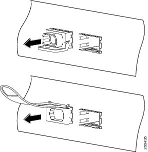 |
How to Remove or Install a PLIM
A PLIM provides the data interfaces for the routing system and mates with its associated MSC through the chassis midplane.
This section contains the following procedures:
Removing a PLIM
This section describes how to remove a PLIM from the line card chassis.
Caution |
The system may indicate a hardware failure if you do not follow proper procedures. Remove or install only one PLIM at a time. Allow at least 15 seconds for the system to complete the preceding tasks before removing or installing another PLIM. |
Required Tools and Equipment
You need the following tools to remove a PLIM:
- ESD-preventive wrist strap
- Medium (Number 2) Phillips screwdriver
To remove a PLIM, see the following figure, and follow these steps:
SUMMARY STEPS
- Attach an ESD-preventive wrist strap and follow its instructions for use.
- Identify the card to be replaced, and unplug the interface cables connected to the card. Be sure to note the current connections of the cables to the ports on the PLIM.
- For the 10-GE PLIMs, remove the XENPAK or XFP optics modules from the card and set them aside. See the How to Remove or Install a PLIM Cable Management Bracket section or How to Remove or Install an XFP Module section.
- Loosen the two captive screws holding the card in place.
- Grasp the two card ejector levers and simultaneously pivot both ejector levers 90 degrees (70 degrees for a newer PLIM) away from the front edge of the card carrier to unseat the card from the backplane (see the following figure).
- Grasp the cable management bracket and gently pull the PLIM halfway from the slot.
- Slide the card from the slot, using one hand under the PLIM to support and guide it (see the following figure). Avoid touching the PLIM printed circuit board, components, or any connector pins. Do not lift cards by the cable management bracket; lift them from the bottom.
- Place the PLIM directly into an antistatic sack or other ESD-preventive container.
- Insert another PLIM or an impedance carrier into the empty card slot.
DETAILED STEPS
| Step 1 |
Attach an ESD-preventive wrist strap and follow its instructions for use. |
||||||
| Step 2 |
Identify the card to be replaced, and unplug the interface cables connected to the card. Be sure to note the current connections of the cables to the ports on the PLIM.
|
||||||
| Step 3 |
For the 10-GE PLIMs, remove the XENPAK or XFP optics modules from the card and set them aside. See the How to Remove or Install a PLIM Cable Management Bracket section or How to Remove or Install an XFP Module section. |
||||||
| Step 4 |
Loosen the two captive screws holding the card in place. |
||||||
| Step 5 |
Grasp the two card ejector levers and simultaneously pivot both ejector levers 90 degrees (70 degrees for a newer PLIM) away from the front edge of the card carrier to unseat the card from the backplane (see the following figure). |
||||||
| Step 6 |
Grasp the cable management bracket and gently pull the PLIM halfway from the slot. |
||||||
| Step 7 |
Slide the card from the slot, using one hand under the PLIM to support and guide it (see the following figure). Avoid touching the PLIM printed circuit board, components, or any connector pins. Do not lift cards by the cable management bracket; lift them from the bottom. |
||||||
| Step 8 |
Place the PLIM directly into an antistatic sack or other ESD-preventive container. |
||||||
| Step 9 |
Insert another PLIM or an impedance carrier into the empty card slot. 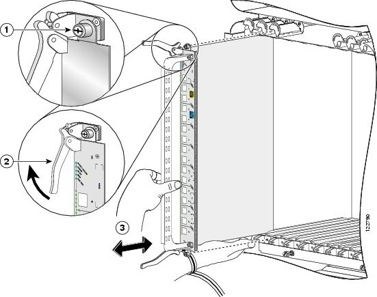
|
Installing a PLIM
This section describes how to install a PLIM in the line card chassis. You can install a PLIM in any slot not occupied by a route processor (RP) card (or a fan controller card, 16-slot chassis only). If you install a new MSC or PLIM, you must first remove the impedance carrier card from the available slot.
Caution |
The system may indicate a hardware failure if you do not follow proper procedures. Remove or install only one PLIM at a time. Allow at least 15 seconds for the system to complete the preceding tasks before removing or installing another PLIM. |
Required Tools and Equipment
You need the following tools and part to install a PLIM:
- ESD-preventive wrist strap
- Medium (Number 2) Phillips screwdriver
- PLIM
Steps
To install a PLIM, see the previous figure, and follow these steps:
SUMMARY STEPS
- Attach the ESD-preventive wrist strap and follow its instructions for use.
- Remove the PLIM from its antistatic packaging.
- Remove the PLIM impedance carrier from the slot you need to fill and set it aside.
- Grasp the cable management bracket with one hand and place your other hand under the carrier to support and guide the card into the correct slot. Slide the card halfway into the correct slot. Avoid touching the card circuitry or any connectors.
- Pivot both card ejector levers so that the openings on the card ejector cams at the top and bottom of the card pass over the tabs on each side of the card cage slot.
- Continue sliding the card into the card cage slot until the openings on the card ejector cams engage the tabs on each side of the card cage slot.
- To seat the card in the midplane connector, grasp both card ejector levers and pivot them inward toward the handle in the card carrier until they are flush against the front edge of the card carrier.
- Engage both captive screws on the PLIM, and then tighten the screws.
- For the 10-GE PLIM, install the XENPAK or XFP optics modules. See the How to Remove or Install a PLIM Cable Management Bracket section or How to Remove or Install an XFP Module section.
- If this PLIM is new, install the PLIM cable management bracket. See the Removing a PLIM Cable Management Bracket section.
- Install the interface cables. We recommend that you clean the fiber-optic connections before attaching the cables. For cleaning instructions, see: http://www.cisco.com/warp/public/127/cleanfiber2.html .
- If this PLIM is new, configure it for operation. For instructions, see Cisco IOS XR Interface and Hardware Component Configuration Guide and Cisco IOS XR Interface and Hardware Component Command Reference , available at:
DETAILED STEPS
| Step 1 |
Attach the ESD-preventive wrist strap and follow its instructions for use. |
||||
| Step 2 |
Remove the PLIM from its antistatic packaging. |
||||
| Step 3 |
Remove the PLIM impedance carrier from the slot you need to fill and set it aside.
|
||||
| Step 4 |
Grasp the cable management bracket with one hand and place your other hand under the carrier to support and guide the card into the correct slot. Slide the card halfway into the correct slot. Avoid touching the card circuitry or any connectors. |
||||
| Step 5 |
Pivot both card ejector levers so that the openings on the card ejector cams at the top and bottom of the card pass over the tabs on each side of the card cage slot.
|
||||
| Step 6 |
Continue sliding the card into the card cage slot until the openings on the card ejector cams engage the tabs on each side of the card cage slot.
|
||||
| Step 7 |
To seat the card in the midplane connector, grasp both card ejector levers and pivot them inward toward the handle in the card carrier until they are flush against the front edge of the card carrier. |
||||
| Step 8 |
Engage both captive screws on the PLIM, and then tighten the screws.
|
||||
| Step 9 |
For the 10-GE PLIM, install the XENPAK or XFP optics modules. See the How to Remove or Install a PLIM Cable Management Bracket section or How to Remove or Install an XFP Module section. |
||||
| Step 10 |
If this PLIM is new, install the PLIM cable management bracket. See the Removing a PLIM Cable Management Bracket section. |
||||
| Step 11 |
Install the interface cables. We recommend that you clean the fiber-optic connections before attaching the cables. For cleaning instructions, see: http://www.cisco.com/warp/public/127/cleanfiber2.html . |
||||
| Step 12 |
If this PLIM is new, configure it for operation. For instructions, see Cisco IOS XR Interface and Hardware Component Configuration Guide and Cisco IOS XR Interface and Hardware Component Command Reference , available at: http://www.cisco.com/univercd/cc/td/doc/product/ioxsoft/iox33/index.html
|
Verifying the Installation of a PLIM
This section describes how to verify that a PLIM has been properly installed. See the figure showing the front panel of your PLIM for the locations of the port and Status LEDs on the front panel of the PLIM (see 20-Port 1-GE Flex PLIM Front Panel for the 20-port 1-GE PLIM with SFP optics modules or see 14-Port 10-GE XFP PLIM front panel for the 14-port 10-GE XFP PLIM).
If a PLIM fails to operate or power up on installation:
- Make sure that the PLIM is seated firmly in the line card chassis slot. One easy way to verify physical installation is to see whether the front faceplate of the PLIM is even with the fronts of the other PLIMs installed in the card cage.
- Make sure that the corresponding MSC is installed and operating correctly.
- Check whether the ejector levers are latched and that the captive screws are fastened properly. If you are uncertain, unlatch the levers, loosen the screws, and attempt to reseat the PLIM.
- Determine whether there are any active alarms by looking at the alarm LEDs on the alarm module (16-slot chassis) or the route processor (8-slot or 4-slot chassis). See Cisco CRS-1 Carrier Routing System Line Card Chassis System Description for more information about alarms.
- Examine the power shelves (16-slot chassis) or power distribution units (PDUs) (8-slot and 4-slot chassis) to see whether the chassis, as a whole, is receiving power.
Use the LEDs on the PLIM to verify the correct installation and operation of the card.
How to Remove or Install a PLIM Cable Management Bracket
Cisco CRS chassis include a cable management system that organizes the interface cables entering and exiting the router, keeping them out of the way and free of sharp bends.
Caution |
Excessive bending of interface cables can damage the cables. |
The cable management system consists of two separate components:
- The line card chassis arrives preinstalled with a horizontal cable management bracket on the front of the chassis and an optional horizontal cable management bracket available for the rear of the chassis. The cable management system organizes the interface cables entering and exiting the different cards, keeping them out of the way and free of sharp bends. See the appropriate Cisco CRS installation guide for more information on the chassis cable management bracket.
- A cable management bracket that attaches to a PLIM.
This section describes how to remove and install the two types of PLIM cable management bracket. The following shows the PLIM cable management bracket. PLIM Articulated Cable Management Bracket shows the articulated PLIM cable management bracket, designed for installing on the 20-port 1-GE FLEX PLIM and the 42-port 1-GE XFP PLIM.
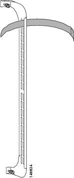
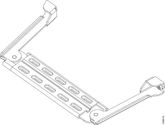
Note the following:
- The front leg of the articulated PLIM cable management bracket is light gray. The articulated bracket can be moved for ease of cabling or uncabling. Always connect your interface cables starting with the interface at the top of the PLIM and always disconnect your interface cables starting with the interface at the bottom of the PLIM.
- For details about replacing a SFP from a line card that uses an articulated bracket, see Replacing a SFP on a Line Card that Uses an Articulated Bracket.
- You do not have to remove the interface cables from the PLIM cable management bracket. If you are replacing the PLIM, you can remove the cable management bracket from the PLIM. After you install a new PLIM, you can attach the cable management bracket to the new PLIM and reattach the interface cables. See the Removing and Installing Fiber-Optic Interface Cables section.
Caution |
Do not use the cable management bracket alone as a handle to pull out or push in the PLIM. One hand must be under the PLIM to support its weight when carrying the PLIM. The cable management bracket is designed to hold the interface cables and may break if you use the bracket to push, pull, or carry the PLIM after it is removed from the router. |
Required Tools and Equipment
You need the following tools and part to remove or install a PLIM cable management bracket:
- ESD-preventive wrist strap
- Medium (Number 2) Phillips screwdriver
- PLIM
- PLIM cable management bracket
Removing a PLIM Cable Management Bracket
To remove a PLIM cable management bracket, follow the steps below. For an example of a fixed PLIM cable management bracket refer to PLIM Cable Management Installation and Removal (the 10-GE PLIM is shown in the illustration, but the installation procedure is similar for all PLIMs). For an example of an articulated PLIM cable management bracket designed for installing on the 20-port 1-GE FLEX PLIM refer to Articulated PLIM Cable Management Bracket Installation and Removal (20-Port PLIM) and for an example of an articulated PLIM cable management bracket designed for installing on the 42-port 1-GE XFP PLIM refer to Articulated PLIM Cable Management Bracket Installation and Removal (42-Port PLIM).
SUMMARY STEPS
- Attach an ESD-preventive wrist or ankle strap and follow its instructions for use.
- Note the current interface cable connections to the ports on each PLIM.
- Starting with the interface cable for the bottom port on the PLIM, disconnect the cable from the PLIM interface.
- Proceed upward and remove the interface from the Velcro strap on the end of the cable standoff (see callout 2 on PLIM Cable Management Installation and Removal, Articulated PLIM Cable Management Bracket Installation and Removal (20-Port PLIM), or Articulated PLIM Cable Management Bracket Installation and Removal (42-Port PLIM)). Avoid any tight twists or sharp bends in the cable.
- Repeat Step 3 and Step 4 for all remaining interface cables, then proceed to next step.
- Loosen the captive installation screw at each end of the cable management bracket and remove the bracket from the PLIM.
DETAILED STEPS
| Step 1 |
Attach an ESD-preventive wrist or ankle strap and follow its instructions for use. |
||||||||||||||||||||||||
| Step 2 |
Note the current interface cable connections to the ports on each PLIM. |
||||||||||||||||||||||||
| Step 3 |
Starting with the interface cable for the bottom port on the PLIM, disconnect the cable from the PLIM interface.
|
||||||||||||||||||||||||
| Step 4 |
Proceed upward and remove the interface from the Velcro strap on the end of the cable standoff (see callout 2 on PLIM Cable Management Installation and Removal, Articulated PLIM Cable Management Bracket Installation and Removal (20-Port PLIM), or Articulated PLIM Cable Management Bracket Installation and Removal (42-Port PLIM)). Avoid any tight twists or sharp bends in the cable. 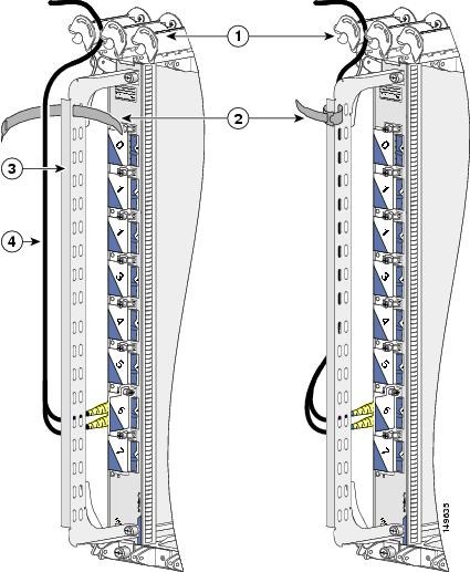
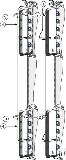
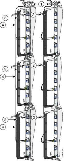
|
||||||||||||||||||||||||
| Step 5 |
Repeat Step 3 and Step 4 for all remaining interface cables, then proceed to next step. |
||||||||||||||||||||||||
| Step 6 |
Loosen the captive installation screw at each end of the cable management bracket and remove the bracket from the PLIM. |
Installing a PLIM Cable Management Bracket
To install a PLIM cable management bracket, follow these steps:
SUMMARY STEPS
- Attach an ESD-preventive wrist or ankle strap and follow its instructions for use.
- Attach the PLIM cable management bracket to the PLIM as follows:
- Carefully wrap the cables with the supplied Velcro strap (refer to callout 2 on PLIM Cable Management Installation and Removal, Articulated PLIM Cable Management Bracket Installation and Removal (20-Port PLIM), or Articulated PLIM Cable Management Bracket Installation and Removal (42-Port PLIM)). Avoid any tight twists or sharp bends in the cable.
DETAILED STEPS
| Step 1 |
Attach an ESD-preventive wrist or ankle strap and follow its instructions for use. |
| Step 2 |
Attach the PLIM cable management bracket to the PLIM as follows: |
| Step 3 |
Carefully wrap the cables with the supplied Velcro strap (refer to callout 2 on PLIM Cable Management Installation and Removal, Articulated PLIM Cable Management Bracket Installation and Removal (20-Port PLIM), or Articulated PLIM Cable Management Bracket Installation and Removal (42-Port PLIM)). Avoid any tight twists or sharp bends in the cable. |
Before You Remove or Install a Transceiver Module
Review the following sections carefully before you remove or install any type of transceiver module:
Safety Guidelines
Before you perform any procedure in this document, review the safety guidelines in this section to avoid injuring yourself or damaging the equipment. See the Laser Safety section.
The following guidelines are for your safety and to protect equipment. The guidelines do not include all hazards. Be alert.
Note |
Review the safety warnings listed in Regulatory Compliance and Safety Information for the Cisco CRS-1 Carrier Routing System before installing, configuring, or troubleshooting any installed card. |
- Never attempt to lift an object that might be too heavy for you to lift by yourself.
- Keep the work area clear and dust free during and after installation. Do not allow dirt or debris to enter into any laser-based components.
- Keep tools and router components away from walk areas.
- Do not wear loose clothing, jewelry, and other items that could get caught in the router while working with OIMs, SFCs, and their associated components.
- Use Cisco equipment in accordance with its specifications and product-usage instructions.
- Do not work alone if potentially hazardous conditions exist.
- Make sure your installation follows national and local electrical codes: in the United States, National Fire Protection Association (NFPA) 70, United States National Electrical Code; in Canada, Canadian Electrical Code, part I, CSA C22.1; in other countries, International Electrotechnical Commission (IEC) 60364, part 1 through part 7.
- Connect only a DC power source that follows the safety extra-low voltage (SELV) requirements in UL/CSA/IEC/EN 60950-1 and AS/NZS 60590 to the FCC DC-input power system.
- Make sure that you have a readily accessible two-poled disconnect device incorporated in the fixed wiring of an LCC configured with the DC-input power system.
- The LCC requires short-circuit (overcurrent) protection to be provided as part of the building installation.
Preventing Electrostatic Discharge
Electrostatic discharge (ESD) damage, which can occur when electronic cards or components are improperly handled, results in complete or intermittent failures. We recommend that you use an ESD-preventive strap whenever you handle network equipment or components.
Following are guidelines for preventing ESD damage:
- Always use an ESD-preventive wrist or ankle strap, and ensure that it makes good skin contact. Connect the equipment end of the connection cord to an ESD connection socket on the router or a bare metal surface on the chassis.
- Handle a card by its ejector levers, when applicable, or metal carrier only; avoid touching the board or connector pins.
- Place a removed card component side up on an antistatic surface or in a static-shielding bag. If you plan to return the component to the factory, immediately place it in a static-shielding bag.
- Avoid contact between the card and clothing. The wrist strap protects the board only from ESD voltage on the body; ESD voltage on clothing can still cause damage.
Guidelines for Card Installation and Removal
Guidelines for card installation and removal include the following:
- Online insertion and removal (OIR) is supported, enabling you to remove and install cards while the router is running. OIR is seamless to users on the network, maintains all routing information, and ensures session preservation. Notifying the software or resetting the power is not required. However, you have the option of using the shutdown command before removing a card.
- Each PLIM and its corresponding MSC function as a pair. If either card is removed, the other card is essentially powered down (although the router can still identify and inventory the cards).
- PLIMs in the line card chassis are attached to the chassis by way of a pair of ejector levers and captive screws. The two ejector levers are used to release the PLIM from its midplane connector. The ejector levers and captive screws are located on the upper and lower ends of the faceplate of the card (see the following figure).
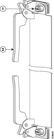
|
1 |
Captive screw |
2 |
Ejector lever |
Caution |
When you remove a PLIM, always use the ejector levers to ensure that the connector pins disconnect from the midplane in the sequence expected by the router.The router can indicate a hardware failure if you do not follow proper procedures. Remove or install only one card at a time. Wait at least 15 seconds before removing or installing another card. |
About PLIM Impedance Carriers
A PLIM impedance carrier must be installed in each empty PLIM slot in the Cisco CRS chassis (see the following figure). The impedance carrier preserves the integrity of the chassis and is required for EMI compliance and proper cooling in the chassis.
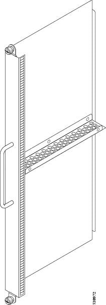
Regulatory, Compliance, and Safety Information
This section contains information on laser safety.
For other regulatory, compliance, and safety information, including translated safety warnings, see the Regulatory Compliance and Safety Information for the Cisco CRS-1 Carrier Routing System publication.
Laser Safety
Do not stare into operational transceiver module ports. The following laser warning applies:
Warning |
Because invisible laser radiation may be emitted from the aperture of the port when no cable is connected, avoid exposure to laser radiation and do not stare into open apertures. Statement 70 |
Obtaining Documentation and Submitting a Service Request
For information on obtaining documentation, using the Cisco Bug Search Tool (BST), submitting a service request, and gathering additional information, see What's New in Cisco Product Documentation, at: http://www.cisco.com/c/en/us/td/docs/general/whatsnew/whatsnew.html.
Subscribe to What's New in Cisco Product Documentation, which lists all new and revised Cisco technical documentation as an RSS feed and delivers content directly to your desktop using a reader application. The RSS feeds are a free service, and Cisco currently supports RSS Version 2.0.
 Feedback