Introduction to this Document
This Release Notes document provides information about the Cisco Catalyst IR1101 Rugged Series Routers, Cisco Catalyst IR1800 Rugged Series Routers, Cisco Catalyst IR8140 Heavy Duty Series Routers, Cisco Catalyst IR8340 Rugged Series Routers, and Cisco ESR6300 Embedded Series Routers running Cisco IOS XE 17.9.1.
This document describes the new features, limitations, troubleshooting, besides providing recommended configurations, caveats, and information on how to obtain support and documentation.
 Note |
The documentation set for this product strives to use bias-free language. For purposes of this documentation set, bias-free is defined as language that does not imply discrimination based on age, disability, gender, racial identity, ethnic identity, sexual orientation, socioeconomic status, and intersectionality. Exceptions may be present in the documentation due to language that is hardcoded in the user interfaces of the product software, language used based on RFP documentation, or language that is used by a referenced third-party product. |
Cisco Catalyst IR1101 Rugged Series Router

The Cisco Catalyst IR1101 Rugged Series Router is a next-generation modular industrial router, which has a base platform with additional pluggable modules that can be added. The pluggable modules provide the flexibility of adding different interfaces to the IR1101 platform, for example, a cellular module, which provides 5G and Fourth-Generation Long-Term Evolution (4G LTE) cellular networks.
The IR1101 also has expansion modules that adds key capabilities to the IR1101. The expansion modules are:
|
SKU ID |
Description |
|---|---|
|
IRM-1100-SPMI |
Expansion Module with 1 GE SFP, 1 Pluggable Module, 4 GPIO ports on 1 Digital I/O Connector, and 1 mSATA SSD Slot. |
|
IRM-1100-SP |
Expansion Module with 1 GE SFP and1 Pluggable Module. |
|
IRM-1100-4A2T |
Expansion Module with an additional four asynchronous serial ports and two Ethernet RJ45 LAN interfaces. |
|
Cellular pluggable modules |
A number of pluggable modules are available for cellular connectivity. |
|
IRM-SSD-100G |
100 GB pluggable industrial SSD. |
Cisco Catalyst IR1800 Rugged Series Router
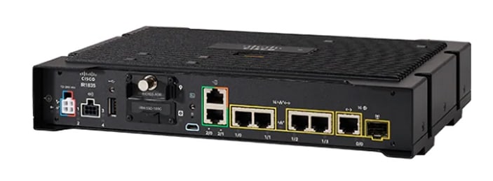
The Cisco Catalyst IR1800 Rugged Series Router is a modular industrial router. The IR1800 series has four base platforms with additional pluggable modules that can be added. The pluggable modules provide the flexibility of adding different interfaces to the base platform.
The IR1800 series consists of four base platforms:
-
IR1821
-
IR1831
-
IR1833
-
IR1835
The IR1800 series features a base platform with modularity, that includes:
|
SKU ID |
Description |
|---|---|
|
IRM-GNSS-ADR |
GPS Module with automotave dead reckoning. |
|
WP-WIFI6-x |
Wi-Fi 6 Network Interface Module (NIM). |
|
Cellular pluggable modules |
A number of pluggable modules are available for cellular connectivity. |
|
IRM-SSD-100G |
100 GB pluggable industrial SSD. |
|
Feature |
IR1821 |
IR1831 |
IR1833 |
IR1835 |
|---|---|---|---|---|
|
Processor Frequency |
600 MHz |
600 MHz |
600 MHz |
1200 MHz |
|
DDR Memory |
4 GB |
4 GB |
4 GB |
8 GB |
|
Flash Storage |
4 GB |
4 GB |
4 GB |
8 GB |
|
PIM Slot |
1 |
2 |
2 |
2 |
|
Wi-Fi NIM Module Slot |
1 |
1 |
1 |
1 |
|
PoE |
No |
No |
Yes |
Yes |
|
SSD Module Slot |
No |
No |
Yes |
Yes |
|
GPS FRU Module Slot |
No |
No |
Yes |
Yes |
|
Digital I/O |
No |
No |
No |
Yes |
|
Asynchronous Serial Interface |
(1) RS232 DTE |
(1) RS232 DTE (1) RS232 DCE |
(1) RS232 DTE (1) RS232 DCE |
(1) RS232 DTE (1) RS232 DCE/RS485 |
Cisco Catalyst IR8140 Heavy Duty Series Router
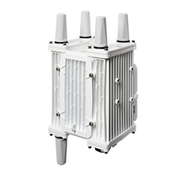
The Cisco Catalyst IR8140 Heavy Duty Series Router (IR8140H), is a next-generation modular IP 66/67 Industrial Router for outdoor use.
These are the two IR8140H models:
-
IR8140H-P-K9 (with PoE PSE)
-
IR8140H-K9 (without PoE PSE)
The IR8140H series features contains four external module slots plus two onboard WAN ports, and supports the following:
-
60-W PSU
-
CPU 1.2 GHz
-
8GB RAM
-
8GB Flash Storage
-
GPS onboard receiver
-
900-MHz WPAN – OFDM/FSK Module
-
4G/LTE and 5G IRMH modules
-
mSATA module
-
1x 1-Gigabit Ethernet SFP WAN
-
1x 1-Gigabit Ethernet Cu WAN
-
PoE (15 W) supported only in the IR8140H-P-K9 PID
-
12VDC_OUT port (only available when PoE is not in use)
-
Battery Backup Units (BBUs): Up to three
-
2x Alarm ports (Digital I/O)
Cisco Catalyst IR8340 Rugged Series Router

The Cisco Catalyst IR8340 Rugged Series Router, is the first all-in-one industrial-grade, integrated routing, switching, and security platform.
The IR8340 router features two Pluggable Interface Module (PIM) slots, two single-wide IRM-NIM slots, plus 12 onboard LAN ports, and two WAN ports, and supports the following:
-
150W or 250W PSU, low-voltage DC and high-voltage AC/DC options
-
PTP on LAN ports - Default, power and Dot1as profiles
-
5G and 4G LTE PIM
-
T1/E1 Network Interface Modules (NIM)
-
8-port Asynchronous/Synchronous Network Interface Module (NIM) IRM-NIM-RS232
-
mSATA module
-
2 x 1-G Combo WAN ports
-
4 x 1-G Copper LAN ports
-
4 x 1-G Combo LAN ports
-
4 x 1-G SFP LAN ports
-
PoE PoE+ UPoE (up to 60 W) support on LAN ports 1-4
-
2 x IN and 1 x OUT Alarm ports (RJ45)
Cisco ESR6300 Embedded Series Router

The ESR6300 is a small form factor embedded router module with a board size of 3.0 in. x 3.775 in. (76.2 mm x 95.885 mm).
The more compact design simplifies integration, and offers system integrators the ability to use the Cisco ESR6300 in a wide variety of embedded applications. The ESR module is available with a Cisco-designed cooling plate customized to the ESR, as well as without the cooling plate for system integrators who want to design their own custom thermal solution.
There are two ESR6300 SKUs:
-
ESR-6300-NCP-K9: Embedded Router Board without a cooling plate
-
ESR-6300-CON-K9: Embedded Router Board with a cooling plate
Both of the SKUs offer the following port and module interfaces:
-
Four GE LAN ports
-
Two combo GE WAN ports
-
One USB 3.0 port
-
One mSATA module interface
Interface Naming Conventions
Cisco Catalyst IR1101 Rugged Series Router
The following section shows the names of the interfaces on each of the IoT routers.
| Port |
Naming Convention |
|---|---|
|
Gigabit Ethernet combo port |
GigabitEthernet0/0/0 |
|
Gigabit Ethernet SFP port on IRM-1100 |
GigabitEthernet0/0/5 |
|
Gigabit Ethernet on IRM-1100-4A2T mounted on the Expansion side |
gigabitetherenet 0/0/5 gigabitetherenet 0/0/6 |
|
Fast Ethernet ports |
FastEthernet0/0/1-0/0/4 |
|
Cellular Interface on IR1101 Base |
Cellular 0/1/0 and Cellular 0/1/1 |
|
Cellular Interface on IRM-1100 mounted on the top (EM) side. |
Cellular 0/3/0 and Cellular 0/3/1 |
|
Cellular Interface on IRM-1100 mounted on the bottom (CM) side. |
Cellular 0/4/0 and Cellular 0/4/1 |
|
Asynchronous Serial Interface Base |
Async0/2/0 |
|
IRM-1100-4A2T is mounted on the top (EM) side |
async 0/3/0 async 0/3/1 async 0/3/2 async 0/3/3 |
|
IRM-1100-4A2T is mounted on the bottom (CM) side |
async 0/4/0 async 0/4/1 async 0/4/2 async 0/4/3 |
|
USB |
usbflash0: |
|
mSATA |
msata |
|
IR1101 Base Unit Alarm input |
alarm contact 0 |
|
GPIO on IRM-1100 |
alarm contact 1-4 |
Cisco Catalyst IR1800 Rugged Series Router
| Port |
Naming Convention |
|---|---|
|
Gigabit Ethernet combo port |
GigabitEthernet0/0/0 |
|
Gigabit Ethernet ports |
GigabitEthernet0/1/0 GigabitEthernet0/1/1 GigabitEthernet0/1/2 GigabitEthernet0/1/3 |
|
Cellular Interface |
Cellular 0/4/0 Cellular 0/4/1 Cellular 0/5/0 Cellular 0/5/1 |
|
Asynchronous Serial Interface |
Async0/2/0 Async0/2/1 (when the base platform supports two asynchronous serial interfaces) |
|
Wi-Fi Interface |
Wl0/1/4 |
|
USB |
usbflash0: |
|
mSATA |
msata |
|
GPIO |
alarm contact 1-4 |
Cisco Catalyst IR8140 Heavy Duty Series Router
| Port |
Naming Convention |
|---|---|
|
Gigabit Ethernet ports |
GigabitEthernet0/0/0 GigabitEthernet0/0/1 |
|
Cellular Interface |
Cellular 0/2/0 OR Cellular 0/3/0 |
|
SSD |
Virtual port Group0 |
|
WPAN |
Wpan 0/1/0 Wpan 0/2/0 Wpan 0/3/0 |
|
Digital IO |
alarm contact 1-2 |
Cisco Catalyst IR8340 Rugged Series Router
| Port |
Naming Convention |
|---|---|
|
Gigabit Ethernet WAN ports |
GigabitEthernet0/0/0 GigabitEthernet0/0/1 |
|
Gigabit Ethernet LAN ports |
GigabitEthernet0/1/0 GigabitEthernet0/1/1 GigabitEthernet0/1/2 GigabitEthernet0/1/3 GigabitEthernet0/1/4 GigabitEthernet0/1/5 GigabitEthernet0/1/6 GigabitEthernet0/1/7 GigabitEthernet0/1/8 GigabitEthernet0/1/9 GigabitEthernet0/1/10 GigabitEthernet0/1/11 |
|
Cellular Interface |
Cellular 0/4/0 Cellular 0/4/1 Cellular 0/5/0 Cellular 0/5/1 |
|
NIM Interface (Asynchronous/Synchronous Serial Ports or E1/T1 ports) |
0/2/0 0/2/1 0/3/0 0/3/1 |
|
mSATA SSD |
msata |
|
GPIO |
alarm contact 1-2 |
|
USB Port |
usb0: |
|
Console Port |
Line console 0 |
Cisco ESR6300 Embedded Series Router
| Port |
Naming Convention |
|---|---|
|
Gigabit Ethernet combo port WAN Layer3 |
GigabitEthernet0/0/0 GigabitEthernet0/0/1 |
|
Gigabit Ethernet LAN Layer 2 ports |
GigabitEthernet0/1/0 GigabitEthernet0/1/1 GigabitEthernet0/1/2 GigabitEthernet0/1/3 |
|
Cellular Interface |
Cellular 0/3/0 |
|
USB Port |
usbflash0: (IOS and rommon) |
|
Console Port |
Line console 0 |
Software Images for Cisco IOS XE Release 17.9.1
Note |
You must have a Cisco.com account to download the software. |
Cisco IOS XE Release 17.9.1 includes the following Cisco images.
|
Router |
Image Type |
Filename |
|---|---|---|
|
IR1101 |
Universal |
ir1101-universalk9.17.09.01.SPA.bin |
|
NPE |
ir1101-universal9_npe.17.09.01.SPA.bin |
|
|
IR1800 |
Universal |
IR1800-universalk9.17.09.01.SPA.bin |
|
NPE |
IR1800-universal9_npe.17.09.01.SPA.bin |
|
|
IR8140 |
Universal |
IR8100-universalk9.17.09.01.SPA.bin |
|
NPE |
IR8100-universal9_npe.17.09.01a.SPA.bin |
|
|
IR8340 |
Universal |
IR8340-universalk9.17.09.01.SPA.bin |
|
NPE |
IR8340-universalk9_npe.17.09.01.SPA.bin |
|
|
ESR6300 |
Universal |
c6300-universalk9.17.09.01.SPA.bin |
The latest software downloads for the routers can be found at:
https://software.cisco.com/download/home/286323433
Click the link corresponding to your device to take you to the specific software you are looking for.
New Features in Cisco IOS XE 17.9.1
The following sections describe the major enhancements available in Cisco IOS XE 17.9.1 on each of the routers.
Major Enhancements in IR1101
There are no new features specifically for the IR1101. Please see the Major Enhancements Common to all IoT Routers.
Major Enhancements in IR1800
The following are the new features for the IR1800:
Packet Capture Support for CANBUS
When enabled, this feature will capture packets sent and received on the IR1800 series CANBUS. Once captured, the data will be exported as a packet capture (PCAP) file to allow for further examination. The feature is configured in exec mode and is only temporary, meaning it is not permanent across a reboot/reload.
A file name is required for the capture. The default location for the capture file is at bootflash:/canbus_dumplogs. If the capture is started without specifying the file initially, or after the router is reloaded, you will get the following message when you check the status:
canbus packetdump file pcapfile path bootflash:/canbus_dumplogs/pcapfile didn't startAfter stopping the capture, if you want to start the capture again without specifying the file name, the old specified name will be overwritten.
Use the following command to specify the name of the capture file:
Router#monitor canbus packetdump file <filename>Note |
You do not need to specify the path, the only supported path is the default path bootflash:/canbus_dumplogs |
Use the following command to start the capture using the specified <filename> from the command above:
Router#monitor canbus packetdump startUse the following command to stop the capture:
Router#monitor canbus packetdump stopUse the following command to check the status of the monitoring:
Router#show canbus packetdumpCommand Examples
Router#monitor canbus packetdump ?
file CAN Bus interface packet capture destination file
start CAN Bus interface packet capture start
stop CAN Bus interface packet capture stop

Router#monitor canbus packetdump file canbusfile
Router#show canbus packetdump
canbus packetdump file canbusfile path bootflash:/canbus_dumplogs/canbusfile didn't start

Router#monitor canbus packetdump start
Router#show canbus packetdump
canbus packetdump file canbusfile path bootflash:/canbus_dumplogs/canbusfile started

Router#monitor canbus packetdump stop
Router#show canbus packetdump
canbus packetdump file canbusfile path bootflash:/canbus_dumplogs/canbusfile didn't start
GPS and Dead Reckoning Support for the J1939 Connector
Automotive Dead-Reckoning (DR) refers to the capability of a GNSS receiver to continue to navigate on an automotive platform when there are an insufficient number of GNSS satellite signals available. To do this, the receiver uses information provided by external sensors concerning the state of the vehicle in order to propagate the navigation solution.
Automotive DR requires information regarding the change in directional heading of the vehicle, which is provided by a three-axis digital gyroscope. Automotive DR also requires information about speed and direction of the vehicle. Speed is provided by an odometer (wheel tick) count, which is input into the IRM-GNSS-ADR pluggable module.
The automotive DR feature also accepts data from a three-axis digital accelerometer, which provides information that can be used to determine the orientation of the gyro when it is installed at a tilt angle. This information is also used to estimate elevation. The accelerometer is integrated within the sensor included inside the pluggable module.
Prior to the 17.9.1 release, only mode obdii was available. In 17.9.1, mode j1939 is added with the existing default mode obdii.
The J1939 connector is supported on heavy duty trucks, which provides speed and reverse status data to be fed into the GPS/DR module using J1939 protocol. It is configured through the command line interface under the controller.
Configuration
The following CLIs are available.
To show what is available for dead reckoning:
Router(config-controller)#dead-reckoning ?
enable enable GPS feature
mode DR mode configuration
nmea NMEA Configuration
To configure mode j1939:
Router(config)#controller Gps-Dr
Router(config-controller)#dead-reckoning mode j1939
To view the status:
Router#show platform hardware gps dead-reckoning
=============================
DR Vehicle interface mode: J1939
GPS/DR Vendor Info: TELIT
GPS/DR module FW Version: V33-1.0.5-CLDR-4.7.10-N115R115-003291-3
DR Calibration Status:
DR is not calibrated
Odometer is not calibrated
Gain is not calibrated
Offset is not calibrated

CAN Bus Status:
CAN Bus Tx Count: 1874
CAN Bus Tx error Count: 0

CAN Bus Rx Count: 571
CAN NULL packet Bus RX Count: 0
CAN Bus Rx unsupported packet Count: 448

CAN Bus TX to DR Count: 123
CAN Bus TX to DR error Count: 0

DR data:
DR Sample TimeStamp in usec: 0
DR odometer count received from module: 0
DR odometer count sent to module: 1353
DR odometer is not valid from module
DR odometer delta count from module: 0
DR reverse status: 0

DR in use for location fix: No
time duration for loss of line of sight:
travel distance for loss of line of sight:
travel heading error at exit:
travel yaw error at exit:
travel gyro gain error at exit:
position error at exit:
position error ratio at exit:
position noise error at exit:
Raw Accel Data in X: 0
Raw Accel Data in Y: 0
Raw Accel Data in Z: 0
Raw Gyro Data in X: 0
Raw Gyro Data in Y: 0
Raw Gyro Data in Z: 0
Major Enhancements in IR8140
The following are the new features for the IR8140:
Enhanced Time Distribution for WPAN
When the ntp refclock GPS is configured, and there is a GPS signal with a valid time lock, the WPAN time sync will be done using the 1PPS output of the GPS receiver. When the ntp refclock GPS is not configured, or there is no GPS signal with time lock available, WPAN will sync the time by GPIO.
The feature is configured using the following CLI:
enable gps-based time sync
ntp refclock gps
The following CLI can be used to get information about the state of the pulse-based time sync:
show wpan 0/X/0 hardware time-statsThe following output shows an example of when the GPS signal is working:
Router#show wpan 0/1/0 hardware time-stats
Current pulse source: PPS
Last sync pulse trigger time: 1653442579.000000 (2022:05:25-09:36:19-CST)
Last sync pulse receive time: 1653442578.990649 (2022:05:25-09:36:18-CST)
Total pulses triggered: 4116324
Total pulses received: 4116324
Sync pulses: 34312
Pending offset before last sync: 0.008130
Pending offset after last sync: 0.009342
Current pending offset: 0.008688
Router#
The following output shows an example of when the GPS signal is not working, and the time sync is through the GPIO:
Router#show wpan 0/1/0 hardware time-stats
Current pulse source: SW
Last sync pulse trigger time: 1653443059.000000 (2022:05:25-09:44:19-CST)
Last sync pulse receive time: 1653443058.990649 (2022:05:25-09:44:18-CST)
Total pulses triggered: 4116806
Total pulses received: 4116806
Sync pulses: 34316
Pending offset before last sync: 0.008130
Pending offset after last sync: 0.009342
Current pending offset: 0.008562
Router#
WPAN Time Drift Serviceability
This feature adds support for logging certain information that can be useful to diagnose any issues concerning time drift between IOS XE and the WPAN module.
The feature is disabled by default. Use the following CLI to enable the feature:
interface wpan 0/x/0
time-sync-stats
Then dump the data to a file:
wpan 0/x/0 tss-dumpThe following information will be logged whenever IOS XE sends a time sync update to the WPAN module:
-
Current IOS XE time
-
Difference between IOS and bridge right before sync
-
Response time for the BRIDGE_KEY_GLOBAL_TIME command
-
Difference between IOS XE and bridge right after sync
-
IOS XE local time
When the system clock changes, the following information will be logged:
-
Current IOS time (after the clock change)
-
IOS XE local time
-
Whether or not the change is applied by NTP
Note |
Gradual adjustments during normal NTP operation are not considered clock changes. Only larger changes applied by NTP, and changes as a result of the clock set command are logged. |
Data is stored in a compact binary form in files time_stat<seq>_slot_<slot>. The data is stored in the directory bootflash:/wpan_sys_info/ where <seq> is the sequence number of the log file and <slot> is the slot number of the WPAN interface.
The latest data always gets written to the file with sequence 1. The file rotation/rollover logic is:
-
When the file with sequence 1 reaches 1MB, it gets renamed to sequence 2.
-
If there was previously a file with sequence 2, it gets renamed to 3.
-
If there was previously one with sequence 3 it gets deleted.
For example, time_stat1_slot_<slot> always has the latest data, and time_stat3_slot_<slot> always has the oldest data.
Since there can be a large amount of data, which is intended to be processed externally, there is no CLI to show the data. Instead, an external script is used that can parse the time_stat files and can be used to analyze the data according to the specific problem being debugged. Data is buffered in memory for up to 15 minutes before being written to the file. The following exec command can be used to force all data to be written to the file immediately:
wpan 0/X/0 tss-dump BBU Firmware Upgrade
In IOS XE releases prior to 17.9.1, the BBU firmware was bundled into the IOS XE image. The only way to upgrade the BBU firmware was to upgrade the image.
This feature will add a new CLI which will upgrade the BBU firmware from an image stored in a local file. The firmware images will be signed and the signature will be verified prior to installation. The BBU firmware images will be posted to CCO together with IR1840 images.
In order to limit permissions granted to the BBU process, it will only be allowed to access a directory called "bbu_fw" on the bootflash. Therefore, the firmware files need to be in that directory. The CLI to perform the firmware upgrade is:
request platform hardware battery firmware-update install bootflash:bbu_fw/<file name>Major Enhancements in IR8340
The following are the new features for the IR8340:
Private Voice VLAN
This feature provides support for connecting an IP phone to an access switch port. Voice VLAN on an access port is desirable so that features like port security, dot1x, dynamic access port, and protected port can be configured.
The voice VLAN requires an access port to support dedicated VLAN for voice traffic (as the data traffic on the phone link might deteriorate the voice traffic quality) thus the device can differentiate voice traffic from data traffic and provide QoS for voice traffic and ensure quality.
The Ethernet port will be associated with two VLANs on a voice VLAN port as follows:
-
A native VLAN to carry data traffic.
-
An auxiliary or Voice VLAN to carry voice traffic
The data traffic will be sent either tagged or untagged with the access VLAN id. The phone will send voice traffic tagged with the configured voice VLAN id. The voice VLAN id used by the phone can either be configured manually, or learned through CDP. When the voice VLAN is configured on the access port, the device will instruct the IP phone to send voice traffic over the configured voice VLAN. This is achieved through sending CDP messages to the IP phone indicating the same. QoS configurations can be done on the voice VLAN port in order to provide predictable forwarding of voice traffic and thus ensure voice quality.
Major Enhancements in ESR6300
The following are the new features for the ESR6300:
IPv6 Multicast over PPPoE
This new feature applies to the ESR6300 Router.
PPPoE is a session/connection-oriented protocol, which extends the point-to-point radio frequency (RF) link from an external radio to an IOS router. Router communication with the radio is represented by virtual access interface (connectivity to a radio neighbor).
VMI operates in the Bypass mode where each Virtual Access Interface (VAI) represents a radio neighbor. The VMI layer re-directs unicast routing protocol traffic to the appropriate P2P link (Virtual-Access interface) and replicates any Multicast traffic that needs to flow.
For IPV6 multicast over PPPoE to function properly, the following must be configured:
-
PPPoE (Virtual-template, VMI and physical interface)
-
IPV6 unicast and multicast routing
-
IPv6 PIM BSR
-
IPv6 MLD
Note |
This feature requires the Network Advantage License. |
For additional information, see the IPv6 Multicast over PPPoE chapter.
Major Enhancements Common to all IoT Routers
The following are the new features that are common to all routers:
Install Mode Support
The following table describes the differences between Bundle mode and Install mode:
Cisco IOS XE running on IoT routers has typically made use of the Bundle boot mode. Bundle boot mode is also known as Consolidated boot, and uses a single compressed image. The typical naming convention is <product>-universalk9.<release>.SPA.bin.
This mode provides a consolidated boot process, using local (hard disk, flash) or remote (TFTP) .bin image. Booting via a .bin image means that the router would first have to uncompress the image before booting from it. This led to a longer period of time for the router to boot.
To upgrade the router to a new version of IOS XE, you would point the "boot system" to a new software image. This method is well known and details are available in your products configuration guide.
Starting with IOS XE release 17.9.1, a new boot mode called Install mode has been added to the IoT routers. Install mode uses packages loaded into bootflash, which are read by a packages.conf file. This method provides more control over the software installation process.
Note |
SMU installation was supported in both bundle boot and install mode. From Cisco IOS XE Release 17.9.x, SMU installation will be stopped if the router is booted up in bundle mode. If the router is booted up in install mode, SMU installation will keep working as it is in previous releases. |
|
Bundle Mode |
Install Mode |
|---|---|
|
This mode provides a consolidated boot process, using local (hard disk, flash) or remote (TFTP) .bin image. |
This mode uses the local (bootflash) packages.conf file for the boot process. |
|
This mode uses a single .bin file. |
.bin file is replaced with expanded .pkg files in this mode. |
|
CLI:
|
CLI:
|
|
To upgrade in this mode, point the boot system to the new image. |
To upgrade in this mode, use the install commands. |
|
Image Auto-Upgrade: When a new Field-Replaceable Unit (FRU) is inserted in a modular chassis, manual intervention is required to get the new FRU running with the same version as the active FRUs. |
Image Auto-Upgrade: When a new FRU is inserted in a modular chassis, the joining FRU is auto-upgraded to the image version in sync with the active FRUs. |
|
Rollback: Rollback to the previous image with multiple Software Maintenance Updates (SMUs) may require multiple reloads. |
Rollback: Enables rollback to an earlier version of Cisco IOS XE software, including multiple patches in single reload. |
For additional information, please see Cisco IOS XE Installation Methods.
Cellular Boot Time Improvements
Numerous improvements have been made in the Cellular link up-time with IOS-XE release 17.9.1. In previous releases, the cellular interface was taking approximately two and a half minutes to come up and pass traffic after the router booted up. The Cellular link up-time has been improved by approximately 20% in this release.
IOS XE Downgrade Warning
This feature will present a warning when issuing a boot system flash command followed by a file name of an image which has a version number lower than the one of the running image. The downgrade operation will still be possible by ignoring the warning message presented to the user. Booting an image with the same or higher version of the running image is allowed without warning. The feature is only intended for images already loaded on the bootflash of the router, this means only for the boot system flash <file_name> CLI (excluding other sources/devices like ftp, mop, rpc, tftp, rom).
The following are examples of how the system compares versions:
When comparing two version numbers as follows:
-
17.7.1
-
17.7.1c
The version with the letter (17.7.1c) will be considered the most updated one.
When comparing two version numbers as follows:
-
17.7.3a
-
17.7.3f
The comparison will be made taking into consideration the alphabetical order. In the case above 17.7.3f will be considered the most updated one.
SNMP Polling of Temperature OID
Support has been added for SNMP MIB to be able to return values from temperature sensors. The output should look similar to the show environment CLI.
The output of a show environment on an IR1101:
IR1101#show environment

Number of Critical alarms:  0
Number of Major alarms:     0
Number of Minor alarms:     0

 Slot        Sensor          Current State   Reading        Threshold(Minor,Major,Critical,Shutdown)
 ----------  --------------  --------------- ------------   ---------------------------------------
 R0          Temp: TS1       Normal          42    Celsius      (75 ,80 ,90 ,na )(Celsius)
 R0          Temp: TS2       Normal          37    Celsius      (75 ,80 ,90 ,na )(Celsius)
The output from an snmpwalk would look similar to this:
[root@sg-centos-hv ~]# snmpwalk -v 2c -c public 33.33.33.204 1.3.6.1.4.1.9.9.13.1.3.1
SNMPv2-SMI::enterprises.9.9.13.1.3.1.2.1 = STRING: "Sensor 1"
SNMPv2-SMI::enterprises.9.9.13.1.3.1.3.1 = Gauge32: 48
SNMPv2-SMI::enterprises.9.9.13.1.3.1.4.1 = INTEGER: 93
SNMPv2-SMI::enterprises.9.9.13.1.3.1.5.1 = INTEGER: 0
SNMPv2-SMI::enterprises.9.9.13.1.3.1.6.1 = INTEGER: 1
SNMPv2-SMI::enterprises.9.9.13.1.3.1.7.1 = INTEGER: 0
The ciscoEnvMonTemperatureStatusEntry oid is 1.3.6.1.4.1.9.9.13.1.3.1:
-
ciscoEnvMonTemperatureStatusIndex (.1)
-
ciscoEnvMonTemperatureStatusDescr (.2)
-
ciscoEnvMonTemperatureStatusValue (.3)
-
ciscoEnvMonTemperatureThreshold (.4)
-
ciscoEnvMonTemperatureLastShutdown (.5)
-
ciscoEnvMonTemperatureStatus (.6)
GPS Mode Enabled By Default
In IOS XE versions prior to 17.9.1, GPS was enabled by defaut, however, GPS Mode was disabled by default. This required that the user perform an additional modem power-cycle after the router came up in order to use GPS.
Starting with IOS XE 17.9.1, GPS Mode will be enabled by default, and will be set to standalone mode. This will help reduce the cellular link up time.
Note |
This only applies to the cellular based GPS. This does not apply to the GPS/GNSS module in IR1800 (DR module), IR8140 (native GPS) and IR8340 (Timing module). |
Use the following command to check cellular GPS status:
Router# show cellular <slot> gps
auto-reset Enable reset modem automatically after configuring GPS enable or mode
Cisco WebUI Access Point Name (APN)
IOS XE 17.9.1 added the ability to add, edit, or delete the APN from the Cisco WebUI Interface. The following provides an overview of how to perform this function.
Note |
This section only describes new functionality and is not a complete overview of the WebUI. |
Adding the APN
From the WebUI, navigate to Configuration > Interface > Cellular. Double click on the cellular interface based upon your platform.
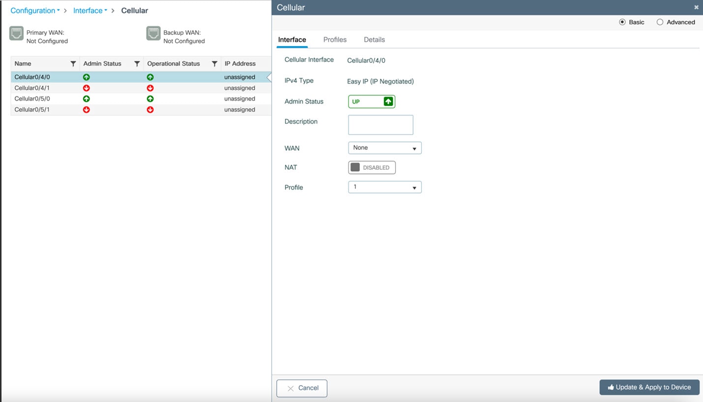
On the Cellular window, click on the Profiles tab.

From the Profiles tab, you can Add, Delete, or Edit the APN. Once the profile is modified, click on Update & Apply to Device at the bottom of the window.
Changing the SIM Slot
By default, the APN is attached to SIM slot 0. You can change the APN to SIM slot 1 by using the WebUI.
From the WebUI, navigate to Configuration > Interface > Cellular. Click on the Advanced radio button on the top of the window.

Click on the Controller tab at the top of the window.
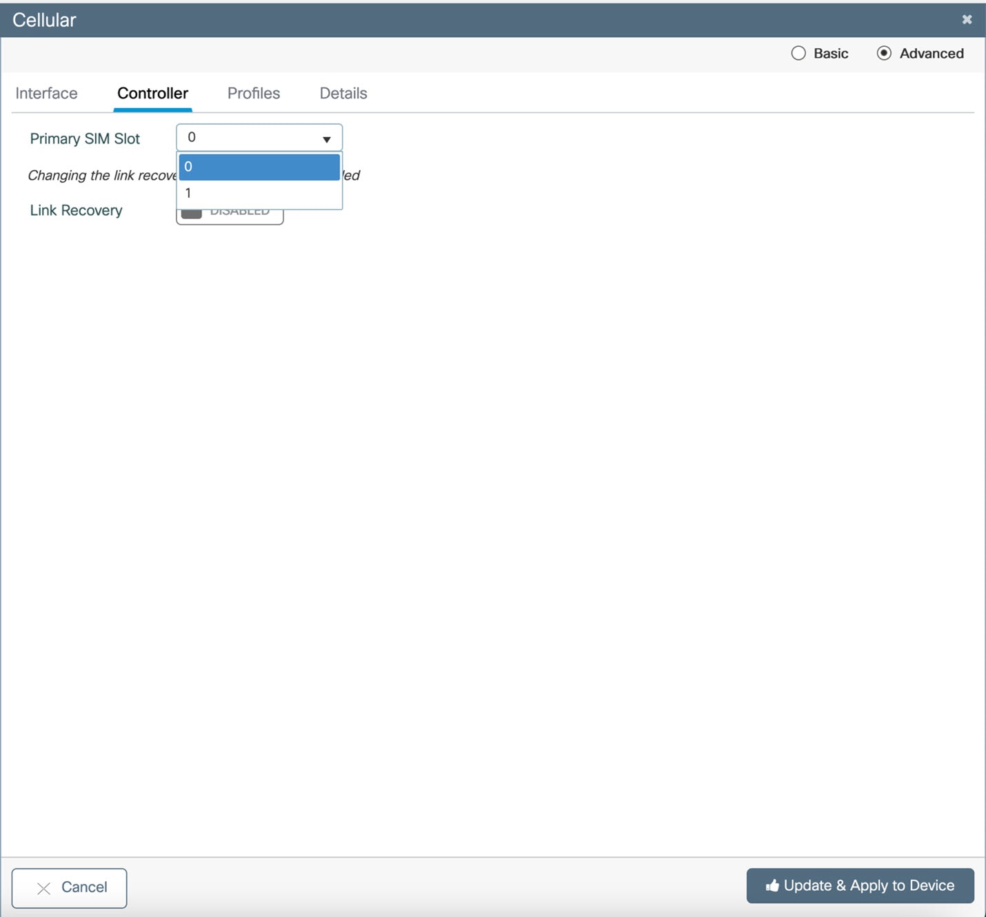
Click on the Primary SIM Slot pull-down and select slot 1. Click on Update & Apply to Device on the bottom of the window.
TLS 1.3 Support
HTTPS supports secure TLS version TLSv1.3 in Cisco IOS XE 17.9.1 and later.
Related Documentation
Cisco Catalyst IR1101 Rugged Series Router
Cisco Catalyst IR1800 Rugged Series Router
Cisco Catalyst IR8140 Heavy Duty Series Router
Cisco Catalyst IR8340 Rugged Series Router
Cisco ESR6300 Embedded Series Router
Product Independent Documentation
Cisco Industrial Routers and Industrial Wireless Access Points Antenna Guide
Known Limitations
Smart Licensing Using Policy
Starting with Cisco IOS XE 17.6.1, with the introduction of Smart Licensing Using Policy, even if you configure a hostname for a product instance or device, only the Unique Device Identifier (UDI) is displayed. This change in the display can be observed in all licensing utilities and user interfaces where the hostname was displayed in earlier releases. It does not affect any licensing functionality. There is no workaround for this limitation.
The licensing utilities and user interfaces that are affected by this limitation include only the following: Cisco Smart Software Manager (CSSM), Cisco Smart License Utility (CSLU), and Smart Software Manager On-Prem (SSM On-Prem).
IOx on the ESR6300
Note |
IOx development is not supported on the ESR6300. While this is platform independent code, it is unsupported and untested on this device. |
Config register change issue with service password recovery update
When service password recovery is disabled, then the config register cannot be changed and will be stuck at 0x01. This issue was found on the IR1101 Router. For additional information see the tech note Understand Configuration Register Usage on all Routers.
Standalone MAC Authentication Bypass (MAB) Limitation
Standalone MAC Authentication Bypass (MAB) is an authentication method that grants network access to specific MAC addresses regardless of 802.1X capability or credentials.
Refer to the following table for details:
|
Details |
Release Affected |
Release Fixed |
||
|---|---|---|---|---|
|
MAB/Dot1x may not work if the global type-6 encryption setting is enabled. If users still want to use MAB/Dot1x, they should disable the type-6 encryption and enable type-7 encryption. |
17.4.X 17.5.X 17.6.1 17.6.2 17.7.1 |
17.3.5 Fixed in these future releases: 17.6.3 17.7.2 17.8.1 and later. |
||
|
dACL and device-tracking features are not supported on the IR1101 and ESR6300 due to a hardware limitation. dACL is supported on the IR1800 series. Therefore, features such as MAB and Dot1x should not be used with the optional dACL/device-tracking enabled. |
|
Hardware limitation, no software fix available. |
Caveats
Caveats describe unexpected behavior in Cisco IOS XE releases. Caveats listed as open in a prior release are carried forward to the next release as either open or resolved.
The Cisco Bug Search Tool (BST) is a gateway to the Cisco bug-tracking system, which maintains a comprehensive list of defects and vulnerabilities in Cisco products and software. The BST provides you with detailed defect information about your products and software.
Open Caveats in Cisco IOS XE 17.9.1
To view the details of a caveat, click on the identifier.
|
Identifier |
Description |
Platform |
|---|---|---|
|
FN980: ATT sim attached with wrong profile during sim switching. |
P-5GS6-GL |
|
|
FN980: Modem not able to load correct attach profiles as in controller context. |
P-5GS6-GL |
|
|
VMI Neighbor counters for input packets always show as 0 with DLEP data path traffic. |
ESR6300 |
|
| CSCwc25912 |
PUNT Policer messages when DLEP conf is attached. |
ESR6300 |
|
Line range limitations on controller mode. |
IR1101 |
|
|
High CF/TE,Turnaround and Latency number after reload of router. |
IR8340 |
|
|
WAN SFP link goes down after reloading Peer. |
IR1800 |
|
|
IR8340 throws CPP/FMAN Download errors on attaching ngsw class-map using etype classification. |
IR8340 |
|
|
GLC-T on WAN interface G 0/0/0 is admin down post booting with latest 17.8.1 |
IR8340 |
|
|
PTP Dot1as Latency accuracy is seen 13ms on latest 1781 image |
IR8340 |
|
|
PTP Forward mode functionality is not working. |
IR8340 |
|
|
Last reporter of IGMPV3 report is all "0" if receiver connected on SVI interface. |
IR8340 |
|
|
GPS mode of controller cellular shows not configured |
IR8340 |
|
|
Cellular serviceability feature is not enabled on IR8340 |
IR8340 |
|
|
Telit Modem LM960 FN980 FW upgrade may fail when two Telit modems present in platform |
IR8140 |
|
|
Telit Modem LM960 SIM slot switch may affect the other Telit modems present in platform |
IR8140 |
|
|
"show archive" not displaying & limiting archived configurations=> consuming space + firmw upg fails |
IR1101 |
|
|
SDWAN mode: vManage always fails to push any template to device if device is running in FIPS mode. |
ESR6300 |
Resolved Caveats in Cisco IOS XE 17.9.1
To view the details of a caveat, click on the identifier.
|
Identifier |
Description |
Platform |
||
|---|---|---|---|---|
|
Traffic Classification stats not getting accounted on VAI for DLEP Feature. |
ESR6300 |
|||
|
BBU cell lockout reports stale value after BBU OIR. |
IR8140 |
|||
|
Subject-alt-name attribute in certificate trustpoint causes Windows NDES/CA to reject SCEP requests |
All IoT Routing platforms |
|||
|
Default ignition config in sdwan running config for IoT routing platforms |
All IoT Routing platforms |
|||
|
Correcting show commands for DLEP
|
ESR6300 |
|||
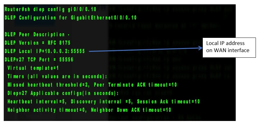
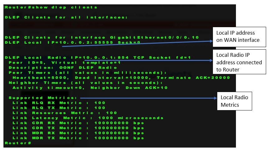
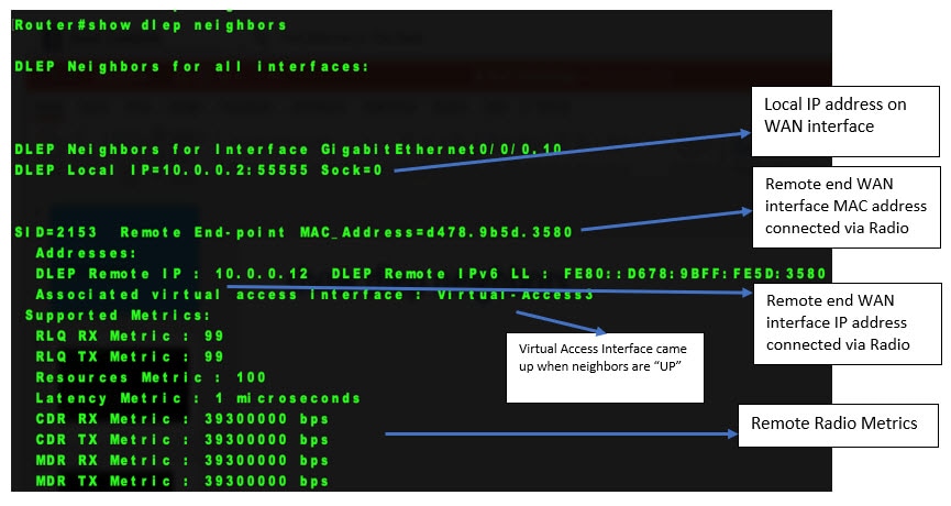
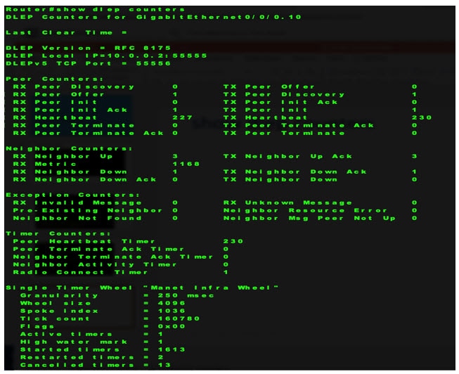
Corrected show Commands for DLEP
This section provides examples of the corrected output of DLEP show commands after fixing the CSCwb42394 caveat.
Communications, Services, and Additional Information
-
To receive timely, relevant information from Cisco, sign up at Cisco Profile Manager.
-
To get the business impact you’re looking for with the technologies that matter, visit Cisco Services.
-
To submit a service request, visit Cisco Support.
-
To discover and browse secure, validated enterprise-class apps, products, solutions, and services, visit Cisco DevNet.
-
To obtain general networking, training, and certification titles, visit Cisco Press.
-
To find warranty information for a specific product or product family, access Cisco Warranty Finder.
Documentation Feedback
To provide feedback about Cisco technical documentation, use the feedback form available in the right pane of every online document.
Cisco Support Community
Cisco Support Community is a forum for you to ask and answer questions, share suggestions, and collaborate with your peers. Join the forum at: https://supportforums.cisco.com/index.jspa.
Cisco Bug Search Tool (BST)
The Cisco Bug Search Tool (BST) is a gateway to the Cisco bug-tracking system, which maintains a comprehensive list of defects and vulnerabilities in Cisco products and software. The BST provides you with detailed defect information about your products and software.
Abbreviated Cisco Trademarks
Cisco and the Cisco logo are trademarks or registered trademarks of Cisco and/or its affiliates in the U.S. and other countries. To view a list of Cisco trademarks, go to this URL: https://www.cisco.com/c/en/us/about/legal/trademarks.html. Third-party trademarks mentioned are the property of their respective owners. The use of the word partner does not imply a partnership relationship between Cisco and any other company. (1721R)
 Feedback