Cisco Nexus 7000 Series NX-OS VXLAN Configuration Guide
Bias-Free Language
The documentation set for this product strives to use bias-free language. For the purposes of this documentation set, bias-free is defined as language that does not imply discrimination based on age, disability, gender, racial identity, ethnic identity, sexual orientation, socioeconomic status, and intersectionality. Exceptions may be present in the documentation due to language that is hardcoded in the user interfaces of the product software, language used based on RFP documentation, or language that is used by a referenced third-party product. Learn more about how Cisco is using Inclusive Language.
- Updated:
- June 23, 2015
Chapter: Configuring VXLAN BGP EVPN
- Information About VXLAN BGP EVPN
- Introducing IP Fabric Overlays (VXLAN)
- Realizing Layer-2 and Layer-3 Multi-Tenancy
- Fabric Overlay Control-Plane (MP-BGP EVPN)
- End Host and Subnet Route Distribution
- ARP Suppression
- Performing End Host Detection, Deletion and Move
- Multi-Destination Traffic
- Guidelines and Limitations for VXLAN BGP EVPN
- Configuring VXLAN BGP EVPN
- Feature History for VXLAN BGP EVPN
Configuring VXLAN
BGP EVPN
This chapter contains the following sections:
Information About VXLAN BGP EVPN
Introducing IP Fabric Overlays (VXLAN)
Motivation for an overlay
An overlay is a dynamic tunnel that transports frames between two endpoints. In a switch-based overlay, the architecture provides flexibility for spine switches and leaf switches.
-
Spine switch table sizes do not increase proportionately when end hosts (physical servers and VMs) are added to the leaf switches.
-
The number of networks/tenants that can be supported in the cluster can be increased by just adding more leaf switches.
How this is achieved is explained in detail later.
VXLAN as the overlay technology
VXLAN is a MAC in IP/UDP overlay that allows layer 2 segments to be stretched across an IP core. All the benefits of layer 3 topologies are thereby available with VXLAN including the popular layer-3 ECMP feature for efficient traffic spread across multiple available paths. The encapsulation and decapsulation of VXLAN headers is handled by a functionality embedded in VXLAN Tunnel End Points (VTEPs). VTEPs themselves could be implemented in software or a hardware form-factor.
VXLAN natively operates on a flood and learn mechanism where BU (Broadcast, Unknown Unicast) traffic in a given VXLAN network is sent over the IP core to every VTEP that has membership in that network. There are two ways to send such traffic: (1) Using IP multicast (2) Using Ingress Replication or Head-end Replication. The receiving VTEPs will decapsulate the packet, and based on the inner frame perform layer-2 MAC learning. The inner SMAC is learnt against the outer Source IP Address (SIP) corresponding to the source VTEP. In this way, reverse traffic can be unicasted toward the previously learnt end host.
- Scalability — VXLAN provides Layer-2 connectivity that allows the infrastructure that can scale to 16 million tenant networks. It overcomes the 4094-segment limitation of VLANs. This is necessary to address today’s multi-tenant cloud requirements.
-
Flexibility— VXLAN allows workloads to be placed anywhere, along with the traffic separation required in a multi-tenant environment. The traffic separation is done using network segmentation (segment IDs or virtual network identifiers [VNIs]).
Workloads for a tenant can be distributed across different physical devices (since workloads are added as the need arises, into available server space) but the workloads are identified by the same layer 2 or layer 3 VNI as the case may be.
-
Mobility— You can move VMs from one data center location to another without updating spine switch tables. This is because entities within the same tenant network in a VXLAN/EVPN fabric setup retain the same segment ID, regardless of their location.
Overlay example:
The example below shows why spine switch table sizes are not increased due to VXLAN fabric overlay, making them lean.
VM A sends a message to VM B (they both belong to the same tenant network and have the same segment VNI). ToR1 recognizes that the source end host corresponds to segment x, searches and identifies that the target end host (VM B) belongs to segment x too, and that VM B is attached to ToR2. Note that typically the communication between VM A and VM B belonging to the same subnet would first entail ARP resolution.
ToR1 encapsulates the frame in a VXLAN packet, and sends it in the direction of ToR2.
The devices in the path between ToR1 to ToR2 are not aware of the original frame and route/switch the packet to ToR2.
ToR2 decapsulates the VXLAN packet addressed to it. It does a lookup on the inner frame. Through its end host database, ToR2 recognizes that VM B is attached to it and belongs to segment x, forwards the original frame to VM B.
 Note | In the following figure, the leaf layer is supported only for F3 modules and not for M3 modules. |

-
VXLAN semantics are in operation from ToR1 to ToR2 through the encapsulation and decapsulation at source and destination VTEPs, respectively. The overlay operation ensures that the original frame/packet content is not exposed to the underlying IP network.
-
The IP network that sends packets from ToR1 to ToR 2 based on the outer packet source and destination address forms the underlay operation. As per design, none of the spine switches need to learn the addresses of end hosts below the ToRs. So, learning of hundreds of thousands of end host IP addresses by the spine switches is avoided.
Learning of (hundreds of thousands of) end host IP and MAC addresses
-
End hosts’ information is available to the attached ToR via First Hop Protocols such as ARP/ND/DHCP etc., when a new bare-metal server or VM is attached.
-
End host to ToR mapping information for each ToR is shared with every other ToR using BGP via a route reflector.
-
Specifically, within BGP, the EVPN address family is employed to carry MAC and IP address information of the end hosts along with other information such as the network and tenant (aka VRF) to which they belong. This allows optimal forwarding of both layer-2 and layer-3 traffic within the fabric.
-
VMs belonging to the same tenant might be many hops apart (though assigned with the same segment ID/VNI), and there might be frequent movement and addition of end hosts. When a new VM comes up or is moved between ToRs, the information is instantly updated into BGP by the detecting ToR thereby ensuring that the updated reachability information is also known to every other ToR.
-
In order to accurately route/switch packets between end hosts in the data center, each participating ToR in a VXLAN cluster must be aware of the end hosts attached to it and also the end hosts attached to other ToRs, in real time.
VXLAN-EVPN fabric— The overlay protocol is VXLAN and BGP uses EVPN as the address family for communicating end host MAC and IP addresses, so the fabric is referred thus.
Realizing Layer-2 and Layer-3 Multi-Tenancy
Using segment IDs or VNIs for multi tenancy in the VXLAN fabric
Typically, when a tenant is created, it is assigned a unique VNI referred to as the layer-3 VNI or the layer 3 segment ID. This serves as a unique identifier for tenant layer-3 context also referred to as the tenant VRF. For each network created within the tenant, a unique identifier is assigned which is referred to as the layer-2 VNI or layer-2 segment-id. The VNIs all come from the same 2^24 – 1 pool represented by the 24-bit VNI identifier carried in the VXLAN header.

Some Segment ID/VNI pointers are given below:
-
If a new VM or physical server for this tenant is added to the data center, it is associated with the same layer-3 VNI, regardless of the physical location. In addition, if it is part of a given tenant network, it is assigned the same layer-2 VNI that identifies that network.
-
By confining server and end host identification of a specific tenant to a unique VNI (or few unique VNIs), segmentation and security are ensured.
-
By ensuring that the VNI-to-end host mapping information on each ToR is updated and shared through the route reflector, the latest information is available through the VXLAN setup.
-
Routing at the ToR/access layer facilitates a more scalable design, contains network failures, and enables transparent mobility.
Traffic between servers in the same tenant network that is confined to the same subnet is bridged. In this case, the VTEPs stamp the layer-2 VNI in the VXLAN header when the communication is between servers that are below different ToRs. The forwarding lookup is based on (L2-VNI, DMAC). For communications between servers that are part of the same tenant but belong to different networks, routing is employed. In this case, the layer-3 VNI is carried in the VXLAN header when communication is between servers below different ToRs. This approach is referred to as the symmetric IRB (Integrated Routing and Bridging) approach, the symmetry comes from the fact that VXLAN encapsulated routed traffic in the fabric from source to destination and vice-versa will carry the same layer-3 VNI. This is shown in the figure below.

In the above scenario, traffic from a server (with layer-2 VNI x) on VTEP V1 is sent to a server (with layer-2 VNI y) on VTEP V2. Since the VNIs are different, the layer-3 VNI (unique to the VRF) is used for communication over VXLAN between the servers.
Fabric Overlay Control-Plane (MP-BGP EVPN)
The main reasons for using BGP EVPN as the overlay control plane are:
-
Standards based—The overlay (VXLAN) and the control plane (BGP) are standards based.
-
Implement control-plane MAC learning so that VMs/servers for each tenant have a unique identity across the fabric.
In a VXLAN-EVPN based fabric, MAC learning occurs via the control plane [through multi-protocol (MP) BGP] instead of the data plane.
When a new end host is attached to a VTEP (aka ToR), the VTEP advertises the MAC and IP address of the end host to a route reflector which in turn advertises it to the other VTEPs through MP-BGP (as shown in the image below). Since MP-BGP enables isolation of groups of interacting agents, VMs/servers that belong to the same tenant are logically isolated from other tenants.

The reasons for using BGP EVPN continues below:
- Reduce flooding
-
Since the number of end hosts attached to VTEPs in a data center is huge, a mechanism is required to reduce flooding for discovery of end host location and resolution information. This is achieved via MAC/IP binding information distribution.
-
MAC address distribution eliminates (or reduces) unknown unicast flooding because MAC addresses are prepopulated.
-
MAC to IP binding information helps in local ARP suppression.
-
- Distributed Anycast Gateway
-
For a given subnet, the same default gateway with the same IP and MAC address is realized simultaneously on appropriate ToR switches thereby ensuring the default gateway for the end hosts is always at its closest point aka its directly attached switch.
-
This ensures that routed traffic is also optimally forwarded within the fabric without going through any tromboning.
-
- VM Mobility Support
-
Efficient
bandwidth utilization and resiliency with Active-Active multipathing
VXLAN is supported with virtual PortChannel (vPC). This allows resiliency in connectivity for servers attached to access switches with efficient utilization of available bandwidth. VXLAN with vPC is also supported for access to aggregation (leaf switch to spine switch) connectivity, promoting a highly available fabric.
-
Secure VTEPs
In a VXLAN-EVPN fabric, traffic is only accepted from VTEPs whose information is learnt via the BGP-EVPN control plane. Any VXLAN encapsulated traffic received from a VTEP that is not known via the control plane will be dropped. In this way, this presents a secure fabric where traffic will only be forwarded between VTEPs validated by the control plane. This is a major security hole in data-plane based VXLAN flood-n-learn environments where a rogue VTEP has the potential of bringing down the overlay network.
- BGP specific motivations
-
Increased flexibility— EVPN address family carries both Layer-2 and Layer-3 reachability information. So, you can build bridged overlays or routed overlays. While bridged overlays are simpler to deploy, routed overlays are easier to scale out.
-
Increased security— BGP authentication and security constructs provide more secure multi-tenancy.
-
Improved convergence time— BGP being a hard-state protocol is inherently non-chatty and only provides updates when there is a change. This greatly improves convergence time when network failures occur.
-
BGP Policies— Rich BGP policy constructs provide policy-based export and import of reachability information. It is possible to constrain route updates where they are not needed thereby realizing a more scalable fabric.
-
Advantages of route reflectors— Increases scalability and reduces the need for a full mesh (coverage) of BGP sessions.
A route reflector in an MP-BGP EVPN control plane acts as a central point for BGP sessions between VTEPs. Instead of each VTEP peering with every other VTEP, the VTEPs peer with a spine device designated as a route reflector. For redundancy purposes, an additional route reflector is designated.
-
End Host and Subnet Route Distribution
Some pointers about end host MAC and IP route distribution in a VXLAN EVPN fabric are given below:
-
When a new end host is attached to a VTEP (say Host A in the below scenario), the VTEP V1 learns the end host’s MAC and IP address. MP-BGP on the VTEP nodes enables advertising of the addresses (IP + MAC) to the route reflector.
Figure 5. New End Host Attaches to a VTEP 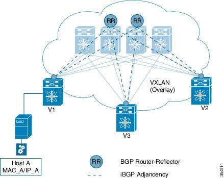
-
MP-BGP also distributes subnet routes and external reachability information between VTEPs. When VTEPs obtain end host routes of remote end hosts attached to other VTEPs, they install the routes in their RIB and FIB.
Note that the end host route distribution is decoupled from the underlay protocol.
End host communication within a VNI and across VNIs
As we know, in a VXLAN EVPN fabric a unique Layer-2 VNI is designated to each tenant network.
Recall, when two end hosts sharing the same layer-2 VNI communicate with each other, the traffic is bridged, and confined to a subnet. When two end hosts in different layer-2 VNIs communicate with each other, the traffic is routed and moves between subnets.
Furthermore, an end host retains its address and tenant association when it moves to another VTEP.
One tenant network, one Layer-2 VNI, and one default gateway IP and MAC address
Since end hosts in a tenant network might be attached to different VTEPs, the VTEPs are made to share a common gateway IP and MAC address for intra-tenant communication.
If an end host moves to a different VTEP, the gateway information remains the same and reachability information is available in the BGP control plane.
Distributed IP anycast gateway
The gateway is referred as a distributed IP anycast gateway, since the gateway is distributed across all relevant VTEPs.
The gateway provides routing and bridging capabilities, and the mechanism is referred as Integrated Routing and Bridging (IRB).
The distributed anycast gateway for routing is completely stateless and does not require the exchange of protocol signalization for election or failover decision.
All VTEPs host active default gateways for their respective configured subnets and First Hop Routing Protocols (FHRP) such as HSRP, VRRP etc. are not needed.
A sample distributed gateway for a setup is given below:

Blue tenant network's configuration
Similar configuration needs to be implemented on the leaf switch V1 and all other switches containing the blue tenant network’s end hosts. Configuration details are provided in BGP EVPN and Overlay Configuration chapter. Similar configuration needs to be implemented for red tenant too.
After the configurations, end host traffic within a VNI (say 30000) is bridged, and traffic between tenant networks is routed. The routing takes place through a Layer-3 VNI (say 50000) typically having a one-on-one association with a VRF instance.
Forwarding between servers within a Layer-2 VNI

The VNI of the source end host, Host A, and the target end host, Host B, is 30000.
-
Host A sends traffic to the directly attached VTEP V1.
-
V1 performs a lookup based on the destination MAC address in the packet header (For communication that is bridged, the target end host’s MAC address is updated in the DMAC field).
-
VTEP V1 bridges the packets and sends it toward VTEP V2 with a VXLAN header stamped with the Layer 2 VNI 30000.
-
VTEP V2 receives the packets, and post decapsulation, lookup, bridges them to Host B.
Packet forwarding between servers belonging to different Layer-2 VNIs
In the below example, the source and target end hosts (Host A and Host F) belong to different Layer-2 virtual networks (with VNIs 30000 and 30001). So, the traffic flow is between subnets, and hence routed. The VRF VNI 50000 is used to route the traffic

-
Host A sends traffic to its default gateway (post ARP resolution) which is configured on the directly attached VTEP V1.
-
V1 performs a FIB lookup based on the destination IP address in the packet header.
-
VTEP V1 routes the packets and sends it toward VTEP V2 with a VXLAN header stamped with the VRF (Layer 3) VNI 50000.
-
VTEP V2 receives the packets, and post decapsulation, routing lookup, and rewrite, sends them to Host F.
Routing at the VTEP - A high level view
Mandatory configurations
-
A VLAN is configured for each segment - sending segment, VRF segment and receiving segment.
-
BGP and EVPN configurations ensure redistribution of this information across the VXLAN setup.
Real time behavior
The source VTEP receives traffic and takes the routing decision. It then stamps the packet with the associated VRF VNI while sending traffic to the destination VTEP, which in turn forwards traffic to the destination server
Communication between a VXLAN overlay and an external network
The data center interconnect (DCI) functionality is implemented on the border device (leaf or spine) of the VXLAN EVPN network. Depending on the type of hand-off to the outside network such as MPLS, LISP, layer-2, and so on, appropriate DCI configuration is required on the border device(s) and the connecting edge device(s) of the outside network.
ARP Suppression
The following section illustrates ARP suppression functionality at VTEP V1 (Refer the ARP Suppression image, given below). ARP suppression is an enhanced function configured under the layer-2 VNI (using the suppress-arp command). Essentially, the IP-MACs learnt locally via ARP as well as those learnt over BGP-EVPN are stored in a local ARP suppression cache at each ToR. ARP request sent from the end host is trapped at the source ToR. A lookup is performed in the ARP suppression cache with the destination IP as the key. If there is a HIT, then the ToR proxies on behalf of the destination with the destination MAC. This is the case depicted in the below image.
In case the lookup results in a MISS, when the destination is unknown or a silent end host, the ToR re-injects the ARP request received from the requesting end host and broadcasts it within the layer-2 VNI. This entails sending the ARP request out locally over the server facing ports as well as sending a VXLAN encapsulated packet with the layer-2 VNI over the IP core. The VXLAN encapsulated packet will be decapsulated by every receiving VTEP that has membership within the same layer-2 VNI. These receiving VTEPs will then forward the inner ARP frame toward the server facing ports. Assuming that the destination is alive, the ARP request will reach the destination, which in turn will send out an ARP response toward the sender. The ARP response is trapped by the receiving ToR, even though ARP response is a unicast packet directed to the source VM, since the ARP-suppression feature is enabled. The ToR will learn about the destination IP/MAC and in turn advertise it over BGP-EVPN to all the other ToRs. In addition, the ToR will reinject the ARP response packet into the network (VXLAN-encapsulate it toward the IP core since original requestor was remote) so that it will reach the original requestor.

Unknown unicast (packet) suppression
Typically, an unknown unicast scenario arises when an end host has resolved the ARP but the MAC address of the end host is not available/updated in the switch.
Unknown unicast traffic from an end host is by default flooded in the VLAN. It is possible to avoid the flooding of this traffic to the overlay network without affecting the flooding of this traffic on local host/sever ports attached to the ToR switch. Use the suppress-unknown-unicast command to do the same.
The suppress unknown unicast function is supported on ToRs/VTEPs in a VXLAN EVPN fabric. This function allows flooding of traffic within the attached switch by including local host/server ports attached to the ToR switch in the output interface index flood list (OIFL) and excluding overlay Layer-3 ports in the hardware.
Performing End Host Detection, Deletion and Move
End host detection by a VTEP device
When a new end host (Host A) is attached to VTEP V1, the following actions occur:
-
VTEP V1 learns Host A's MAC and IP address (MAC_A and IP_A).
-
V1 advertises MAC_A and IP_A to the other VTEPs V2 and V3 through the route reflector.
-
The choice of encapsulation (VXLAN) is also advertised.
A sample depiction of Host A related information:


If Host A moves from VTEP V1 to V3, the following actions occur:

Mobility in a vPC scenario
In a vPC scenario where 2 ToR switches are vPC peers, whether the end host is attached to an orphan port or has a dual homed connection, the VIP address is advertised in the control plane and data plane, and the VIP address is carried in the (outer) source IP address field of the VXLAN packet.
Note | VIP is a common, virtual VTEP IP address that is used for (unicast and multi destination) communication to and from the two switches in the vPC setup. The VIP address represents the two switches in the vPC setup, and is designated as the next hop address (for end hosts in the vPC domain) for reachability purposes. |
Multi-Destination Traffic
Refer to the table below to know the multicast protocol(s) for your Cisco Nexus switches support::
|
If you are using this Nexus switch: |
Use this option for BUM traffic |
|
Cisco Nexus 7000 and 7700/F3 Series |
PIM ASM/SSM or PIM BiDir |
Guidelines and Limitations for VXLAN BGP EVPN
VXLAN BGP EVPN has the following guidelines and limitations:
-
VXLAN EVPN requires the LAN_ENTERPRISE_SERVICES_PKG license.
-
Only spine role is supported in Cisco NX-OS Release 7.2(0)D1(1).
-
VxLAN and Fabric Path features cannot be enabled on the same VDC for F3 and M3 modules.
-
VXLAN BGP EVPN is supported on M3 series modules from Cisco NX-OS Release 7.3(0)DX(1) onwards.
-
Following are not supported for VxLAN BGP EVPN in VDCs having M3 modules:
The following table lists the VXLAN feature support matrix.
|
Feature |
Cisco NX-OS Release 7.2(0)D1(1) |
Cisco NX-OS Release 7.3(0)D1(1) (F3 Modules) |
Cisco NX-OS Release 7.3(0)DX(1) (F3 Modules) |
Cisco NX-OS Release 7.3(0)DX(1) (M3 Modules) |
Cisco NX-OS Release 8.0(1) (M3 Modules) |
|---|---|---|---|---|---|
|
IPv4/v6 unicast L3GW |
Supported |
Supported |
Supported |
Supported |
Supported |
|
LISP Hand-off |
Supported |
Supported |
Supported |
Not Supported |
Not Supported |
|
IPv4/V6 unicast L2GW |
Not Supported |
Supported |
Supported |
Supported |
Supported |
|
vPC Support |
Not Supported |
Supported |
Supported |
Supported |
Supported |
|
IPv4/v6 multicast L2GW |
Not Supported |
Supported |
Supported |
Supported |
Supported |
|
RP on vPC complex |
Not Supported |
Supported |
Supported |
Supported |
Supported |
|
MPLS (L3VPN) Handoff |
Not Supported |
Supported |
Supported |
Not Supported |
Supported |
|
PIM Bidir underlay |
Not Supported |
Supported |
Supported |
Not Supported |
Supported |
|
FEX |
Not Supported |
Supported |
Supported |
Not Supported |
Not Supported |
|
vPC FEX (A-A/S/T) |
Not Supported |
Supported |
Supported |
Not Supported |
Not Supported |
|
Auto Config |
Not Supported |
Supported |
Supported |
Not Supported |
Supported |
|
ARP Suppression |
Not Supported |
Supported |
Supported |
Supported |
Supported |
Configuring VXLAN BGP EVPN
BGP EVPN and Overlay Configuration
The following BGP, EVPN and overlay configurations are required for the Cisco Nexus 7000 Series and 7700 Series switches with F3 and M3 modules:
-
Initial configuration - Install the network virtualization overlay, BGP, and EVPN features on the VTEPs.
-
Layer 2 VNI configurations for tenant networks within a tenant.
(This configuration is applicable only to F3 modules). -
Layer 3 VNI configurations for a tenant.
Note | Though configuration examples are mainly IPv4, IPv6 addresses are also supported in the VXLAN EVPN fabric. |
Cisco NX-OS Release 7.2(0)D1(1) supported only the border spine functionality. Cisco NX-OS Release 7.3(0)DX(1) supports the Cisco Nexus 7000 leaf functionality for F3 modules.
Initial configuration
(config) #
install feature-set fabric
feature-set fabric
feature fabric forwarding
feature interface-vlan
feature ospf
OR
feature isis
You can use either OSPF or IS-IS as the underlay routing protocol.
Note | The install feature-set fabric command should only be used in the admin VDC. When using a VDC, ensure the VDC is of type F3 or M3, for EVPN. A sample configuration is given below: (config) #
vdc test
    limit-resource module-type f3
|
(config) #
feature nv overlay
feature bgp
feature vni
nv overlay evpn
Configure the anycast gateway MAC address
(config) #
fabric forwarding anycast-gateway-mac 0202.0002.0002
Configure BGP L2VPN EVPN address family
(config) #
router bgp 100
   neighbor 10.1.1.53 remote-as 100
     address-family ipv4 unicast
     address-family l2vpn evpn
	       send-community extended
Layer 2 VNI configurations for a tenant network
Note | This configuration is applicable only to F3 modules. |
Create a bridge domain and associate the Layer 2 VNI with it
(config) #
vni 30000
system bridge-domain 200-210
bridge-domain 200
   member vni 30000
While the system bridge-domain command identifies the bridge domain IDs, the bridge-domain command configures the specified bridge domain(s).
Associate a VLAN (or dot1q tag) with the Layer 2 VNI:
(config) #
encapsulation profile vni cisco
  dot1q 50 vni 30000
Associate the encapsulation profile with the server facing interface
(config) #
interface Ethernet 1/12
   no shutdown
   no switchport
   service instance 1 vni
   encapsulation profile cisco default
      no shutdown
Create a loopback interface and assign an IP address to it
(config) #
interface loopback 0
   ip address 10.1.1.54/32
Associate the Layer 2 VNI to the overlay and configure multicast group membership
(config) #
interface nve 1
   no shutdown
   source-interface loopback0
   host-reachability protocol bgp
   member vni 30000
      mcast-group 224.1.33.3
Enable EVPN and associate the Layer 2 VNI to it
Enable route distinguisher and route target functions for the Layer 2 VNI
(config) #
evpn
  vni 30000 l2
    rd auto
    route-target import auto
    route-target export auto
Note that with the Cisco Nexus 7000 Series switches, a VNI is associated with a bridge-domain (1:1). Refer to the respective configuration guide for more information on bridge-domains. The combination of the router BGP command (configured earlier) and the evpn command ensures that BGP EVPN is configured to advertise ‘MAC address + associated host route (optional)’ of servers attached to the VTEP, for the specified Layer 2 VNI. The MAC+IP routes for the hosts are advertised into BGP-EVPN for hosts belonging to layer 2 VNI 30000.
Layer 3 VNI configurations for a tenant
Associate the VRF VNI to the customer VRF
Enable VRF route distinguisher and VRF route target functions for the Layer 3 VNI
(config) #
vrf context coke
   vni 50000
   rd auto
   address-family ipv4 unicast
      route-target both auto evpn
In the above example, the option both is used to import and export routes associated with the Layer 3 VNI 50000. Specifically, the layer-3 routes will be advertised with route-target 100:50000 where 100 is the BGP Autonomous system number and 50000 is the layer-3 VNI.
Associate the VRF VNI to a bridge-domain and associate a BDI to the customer VRF
(config) #
system bridge-domain add 2200
vni 50000
bridge-domain 2200
  member vni 50000

interface bdi2200
  vrf member coke
  ip forward
  no ip redirects
  no shutdown
While the system bridge-domain command identifies the bridge domain IDs, the bridge-domain command configures the specified bridge domain(s).
Add the Layer 3 VRF VNI to the overlay network and enable BGP reachability
(config) #
interface nve 1
   host-reachability protocol bgp
   member vni 50000 associate-vrf
Configure BGP, associate the customer VRF to BGP and enable L2VPN EVPN route distribution
(config) #
router bgp 100
   vrf coke
      address-family ipv4 unicast
         advertise l2vpn evpn
Enable host/server facing BDI (and associate it to a VRF) for Layer 3 connectivity on the distributed anycast gateway
(config) #
interface bdi200
   vrf member coke
   ip address 10.1.1.1/24
   fabric forwarding mode anycast-gateway
   no shutdown
VXLAN BGP EVPN Verification
For verification of MAC routes, refer these commands:
The following is sample output to verify that end host MAC addresses (local and remote) are added to the MAC address table:
switch# show mac address-table dynamic

Note: MAC table entries displayed are getting read from software.
 Use the 'hardware-age' keyword to get information related to 'Age'

 Legend:
        * - primary entry, G - Gateway MAC, (R) - Routed MAC, O - Overlay MAC
        age - seconds since last seen,+ - primary entry using vPC Peer-Link, E -
 EVPN entry
        (T) - True, (F) - False ,  ~~~ - use 'hardware-age' keyword to retrieve
age info

VLAN/BD   MAC Address      Type      age     Secure NTFY Ports/SWID.SSID.LID
---------+-----------------+--------+---------+------+----+------------------

* 200      2010.0000.0010    dynamic   270      F    F   Eth100/1/1
* 200      2010.0000.0011    dynamic   0        F    F   nve1/10.1.1.56
* 200      2010.0000.0012    dynamic   0        F    F   nve1/10.1.1.74
* 200      2010.0000.0013    dynamic   0        F    F   nve1/10.1.1.56
* 200      8080.c800.0038    dynamic   0        F    F   nve1/10.1.1.74
* 1        24e9.b392.316b    dynamic   1190     F    F   Eth100/1/1
The following is sample output for viewing MAC addresses of end hosts across all EVPN instances (EVIs) pertaining to the switch:
switch# show l2route evpn mac all

Topology    Mac Address    Prod   Next Hop (s)
----------- -------------- ------ ---------------
200         2010.0000.0010 Local  Eth100/1/1
200         2010.0000.0011 BGP    10.1.1.56
200         2010.0000.0012 BGP    10.1.1.74
200         2010.0000.0013 BGP    10.1.1.56
200         8080.c800.0038 BGP    10.1.1.74
2200        002a.6ab2.0181 VXLAN  10.1.1.56
2200        8c60.4f14.2efc VXLAN  10.1.1.74
The following sample output displays BGP routing table information for the L2VPN EVPN address family. It includes route distinguisher and next hop information.
switch # show bgp l2vpn evpn

BGP routing table information for VRF default, address family L2VPN EVPN
BGP table version is 198, local router ID is 10.1.1.54
Status: s-suppressed, x-deleted, S-stale, d-dampened, h-history, *-valid, >-best
Path type: i-internal, e-external, c-confed, l-local, a-aggregate, r-redist, I-injected
Origin codes: i - IGP, e - EGP, ? - incomplete, | - multipath, & - backup

   Network            Next Hop            Metric     LocPrf     Weight Path

Route Distinguisher: 10.1.1.54:32967    (L2VNI 30000)
*>l[2]:[0]:[0]:[48]:[2010.0000.0010]:[0]:[0.0.0.0]/216
                      10.1.1.54                          100      32768 i
*>i[2]:[0]:[0]:[48]:[2010.0000.0011]:[0]:[0.0.0.0]/216
                      10.1.1.56                          100          0 i
*>i[2]:[0]:[0]:[48]:[2010.0000.0012]:[0]:[0.0.0.0]/216
                      10.1.1.74                          100          0 i
*>i[2]:[0]:[0]:[48]:[2010.0000.0013]:[0]:[0.0.0.0]/216
                      10.1.1.56                          100          0 i
*>i[2]:[0]:[0]:[48]:[8080.c800.0038]:[0]:[0.0.0.0]/216
                      10.1.1.74                          100          0 i
*>l[2]:[0]:[0]:[48]:[2010.0000.0010]:[32]:[209.165.202.139]/272
                      10.1.1.54                          100      32768 i
*>i[2]:[0]:[0]:[48]:[2010.0000.0011]:[32]:[209.165.202.140]/272
                      10.1.1.56                          100          0 i
*>i[2]:[0]:[0]:[48]:[2010.0000.0012]:[32]:[209.165.202.141]/272
                      10.1.1.74                          100          0 i
*>i[2]:[0]:[0]:[48]:[2010.0000.0013]:[32]:[209.165.202.142]/272
                      10.1.1.56                          100          0 i
*>i[2]:[0]:[0]:[48]:[8080.c800.0038]:[32]:[209.165.202.143]/272
                      10.1.1.74                          100          0 i

Route Distinguisher: 10.1.1.56:3
*>i[5]:[0]:[0]:[24]:[209.165.202.130]:[0.0.0.0]/224
                      10.1.1.56                 0        100          0 ?

Route Distinguisher: 10.1.1.56:32967
*>i[2]:[0]:[0]:[48]:[2010.0000.0011]:[0]:[0.0.0.0]/216
                      10.1.1.56                          100          0 i
*>i[2]:[0]:[0]:[48]:[2010.0000.0013]:[0]:[0.0.0.0]/216
                      10.1.1.56                          100          0 i
*>i[2]:[0]:[0]:[48]:[2010.0000.0011]:[32]:[209.165.202.140]/272
                      10.1.1.56                          100          0 i
*>i[2]:[0]:[0]:[48]:[2010.0000.0013]:[32]:[209.165.202.142]/272
                      10.1.1.56                          100          0 i

Route Distinguisher: 10.1.1.74:32967
*>i[2]:[0]:[0]:[48]:[2010.0000.0012]:[0]:[0.0.0.0]/216
                      10.1.1.74                          100          0 i
*>i[2]:[0]:[0]:[48]:[8080.c800.0038]:[0]:[0.0.0.0]/216
                      10.1.1.74                          100          0 i
*>i[2]:[0]:[0]:[48]:[2010.0000.0012]:[32]:[209.165.202.141]/272
                      10.1.1.74                          100          0 i
*>i[2]:[0]:[0]:[48]:[8080.c800.0038]:[32]:[209.165.202.143]/272
                      10.1.1.74                          100          0 i
The following sample output displays peer VTEP device information.
switch # show nve peers

Interface Peer-IP    State LearnType Uptime   Router-Mac
--------- ---------------  ----- --------- -------- -----------------
nve1      10.1.1.56         Up    CP        1d12h    002a.6ab2.0181
nve1      10.1.1.74         Up    CP        1d12h    8c60.4f14.2efc
For IP host and prefix routes verification, refer these commands:
The following sample output displays tenant (VRF) information
switch # show ip arp vrf coke

Flags: * - Adjacencies learnt on non-active FHRP router
       + - Adjacencies synced via CFSoE
       # - Adjacencies Throttled for Glean
       D - Static Adjacencies attached to down interface

IP ARP Table for context coke
Total number of entries: 1
Address               Age       MAC Address       Interface
209.165.202.144  00:18:23       2010.0000.0010    Bdi200
The following sample output displays tenant (VRF) information
switch # show ip route vrf coke

IP Route Table for VRF "coke"
'*' denotes best ucast next-hop
'**' denotes best mcast next-hop
'[x/y]' denotes [preference/metric]
'%<string>' in via output denotes VRF <string>

10.1.1.0/24, ubest/mbest: 1/0, attached
    *via 10.1.1.1, Bdi10, [0/0], 1d12h, direct
10.1.1.1/32, ubest/mbest: 1/0, attached
    *via 10.1.1.1, Bdi10, [0/0], 1d12h, local
209.165.202.130/27, ubest/mbest: 1/0, attached
    *via 209.165.202.129, Bdi200, [0/0], 1d12h, direct, tag 12345,
209.165.202.129/32, ubest/mbest: 1/0, attached
    *via 209.165.202.129, Bdi200, [0/0], 1d12h, local, tag 12345,
209.165.202.139/32, ubest/mbest: 1/0, attached
    *via 209.165.202.139, Bdi200, [190/0], 1d12h, hmm
209.165.202.140 /32, ubest/mbest: 1/0
    *via 10.1.1.56%default, [200/0], 1d12h, bgp-100, internal, tag 100,  (mpls-vpn)segid 50000 tunnel: 16843064 encap: 1
The following sample output displays MAC - IP address binding for all attached and remote end hosts (learned through the BGP EVPN control plane).
switch # show l2route evpn mac-ip all

Topology ID Mac Address    Prod     Host IP           Next Hop(s)
----------- -------------- ---- --------------------------------------- --------
200         2010.0000.0010 HMM      209.165.202.139    N/A

200         2010.0000.0011 BGP      209.165.202.140    10.1.1.56

200         2010.0000.0012 BGP      209.165.202.141    10.1.1.74

200         2010.0000.0013 BGP      209.165.202.142    10.1.1.56

200         8080.c800.0038 BGP      209.165.202.143    10.1.1.74
The following sample output displays BGP routing table information for Layer-3 VNIs.
switch # show bgp l2vpn evpn

Route Distinguisher: 10.1.1.54:3    (L3VNI 50000)
*>i[2]:[0]:[0]:[48]:[2010.0000.0011]:[32]:[209.165.202.144]/272
                      10.1.1.56                          100          0 i
*>i[2]:[0]:[0]:[48]:[2010.0000.0012]:[32]:[209.165.202.141]/272
                      10.1.1.74                          100          0 i
*>i[2]:[0]:[0]:[48]:[2010.0000.0013]:[32]:[209.165.202.143]/272
                      10.1.1.56                          100          0 i
*>l[5]:[0]:[0]:[24]:[209.165.202.130]:[0.0.0.0]/224
                      10.1.1.54                 0        100      32768 ?
* i                   10.1.1.56                 0        100          0 ?
Feature History for VXLAN BGP EVPN
|
Feature Name |
Releases |
Feature Information |
|---|---|---|
|
VXLAN BGP EVPN |
7.2(0)D1(1) 7.3(0)DX(1) |
This feature was introduced. Support for M3 modules is introduced. |
 Feedback