- Cisco RFGW-10 UEQAM Description
- Installation Methods
- General Rack Installation Guidelines
- Rack-Mounting a Cisco RFGW-10 UEQAM
- Installing the Chassis Installation Brackets
- Installing the Chassis Installation Handles
- Attaching the Chassis Rack-Mount Brackets
- Installing the Cisco RFGW-10 UEQAM in a Rack
- Attaching a Chassis Ground Connection
- Attaching the Cable-Management Bracket
- Connecting Power to Cisco RFGW-10 UEQAM
- Connecting the Lineage Power Shelf to the Cisco RFGW-10
Cisco RFGW-10 UEQAM Installation
This chapter describes the Cisco RFGW-10 Universal Edge QAM (UEQAM) and provides the procedures for installing the Cisco RFGW-10 UEQAM in the equipment racks. It also describes how to connect the interfaces and power cables.
This chapter contains the following sections:
- Cisco RFGW-10 UEQAM Description
- Installation Methods
- General Rack Installation Guidelines
- Rack-Mounting a Cisco RFGW-10 UEQAM
- Installing the Chassis Installation Brackets
- Installing the Chassis Installation Handles
- Attaching the Chassis Rack-Mount Brackets
- Installing the Cisco RFGW-10 UEQAM in a Rack
- Attaching a Chassis Ground Connection
- Attaching the Cable-Management Bracket
- Connecting Power to Cisco RFGW-10 UEQAM
- Connecting the Lineage Power Shelf to the Cisco RFGW-10
Cisco RFGW-10 UEQAM Description
The Cisco RFGW-10 UEQAM supports multiple card modules. It is designed with a single midplane with modules connecting on both sides of the midplane. It supports:
- 2 TCC cards
- 12 RF switch card slots
- 10 Cisco RFGW-10 Universal RF Cards
- 2 Cisco RFGW-10 UEQAM Series Supervisors
- Dual (redundant) DC PEM
- 1 fan tray module
- 1 front panel display
Front View
Figure 3-1 shows the Cisco RFGW-10 UEQAM with the modules installed.
Figure 3-1 Cisco RFGW-10 UEQAM—Front View

Rear View
Figure 3-2 shows the rear of the Cisco RFGW-10 UEQAM with DC PEM installed.
Figure 3-2 Cisco RFGW-10 UEQAM—Rear View

The internal fans draw cooling air into the chassis and across internal components to maintain an acceptable operating temperature (see Figure 3-2). The fans are located at the rear of the chassis in the fan tray module and power supply modules. A two-hole grounding lug is located on the rear left bottom side of the chassis. Two DC PEMs are accessed from the rear of the router.

Note You have already unpacked your chassis and read all the site requirements for your new equipment. Proceed with the installation.

Warning Before you install, operate, or service the system, read the Regulatory Compliance and Safety Information for the Cisco RF Gateway 10 publication. This document provides important safety information you should know before working with the system. Statement 200
Warning This unit is intended for installation in restricted access areas. A restricted access area can be accessed only through the use of a special tool, lock and key, or other means of security. Statement 1017
Warning Only trained and qualified personnel should be allowed to install, replace, or service this equipment. Statement 1030
Warning To prevent personal injury or damage to the chassis, never attempt to lift or tilt the chassis using the handles on modules (such as power supplies, fans, or cards); these types of handles are not designed to support the weight of the unit. Statement 1032
Installation Methods
Rack-mounting is the preferred method of installation for the Cisco RFGW-10 UEQAM. You can mount the chassis:
- Front mount or mid mount
- In a 19-inch wide (standard), four-post equipment rack or two-post, using the rack-mount brackets in the accessory kit
Note The Cisco RFGW-10 UEQAM usually ships fully loaded. It is recommended that you remove the components from the chassis to make the chassis lighter for your rack installation. It is recommended to remove the two DC PEMs, the two Supervisor Cards, and the 10 Universal RF Line Cards.

General Rack Installation Guidelines
When planning your rack installation, consider the following guidelines:
- The Cisco RFGW-10 UEQAM requires a minimum of 13 rack units (22.75 inches or 57.785 cm) of vertical rack space. Measure the proposed rack location before mounting the chassis in the rack.
- Before using a particular rack, check for obstructions (such as a power strip) that could impair rack-mount installation. If a power strip does impair a rack-mount installation, remove the power strip before installing the chassis, and then replace it after the chassis is installed.
- Allow sufficient clearance around the rack for maintenance. If the rack is mobile, you can push it back near a wall or cabinet for normal operation and pull it out for maintenance (installing or moving cards, connecting cables, or replacing or upgrading components). Otherwise, allow 36 inches (91.44 cm) of access to remove field-replaceable units.
- Maintain a minimum clearance of 4 inches (10.16 cm) on the front and the rear of the chassis for the cooling air inlet and exhaust ports, respectively. Avoid placing the chassis in an overly congested rack or directly next to another equipment rack; otherwise, the heated exhaust air from the other equipment can enter the inlet air vents and cause a high temperature condition inside the router.
- Always install the heavier equipment in the lower half of the rack to maintain a low center of gravity to prevent the rack from falling over.
- Install and use the cable-management brackets included with the Cisco RFGW-10 UEQAM to keep the cables organized and out of the way of the cards and processors. Ensure that the cables from the other equipment already installed in the rack do not impair access to the cards or require you to disconnect cables unnecessarily to perform equipment maintenance or upgrades.
- Install rack stabilizers (if available) before you mount the chassis.
- Provide an adequate chassis ground (earth) connection for your Cisco RFGW-10 UEQAM chassis.
In addition to the preceding guidelines, review the precautions for avoiding excessive temperature conditions in the “Electrical Safety” section.
Table 2-3 shows the weight and dimensions of the Cisco RFGW-10 UEQAM.
Rack-Mounting a Cisco RFGW-10 UEQAM
The Cisco RFGW-10 UEQAM can be installed in either front-mount or mid-mount configurations. The chassis rack-mounting flanges must be secured directly to the chassis before lifting it into the rack.
Verifying Rack Dimensions
Before you install the chassis, measure the space between the vertical mounting flanges (rails) on your equipment rack to verify that the rack conforms to the measurements shown in Figure 3-3.
Step 1 Mark and measure the distance between the two holes on the left and right mounting rails. The distance should measure 18.31 inches ± 0.06 inches (46.5 cm ± 0.15 cm).
Note Measure the pairs of holes near the bottom, middle and top of the equipment rack to ensure that the rack posts are parallel.
Step 2 Measure the space between the inner edges of the left front and right front mounting flanges on the equipment rack.
The space must be at least 17.7 inches (45 cm) to accommodate the chassis, which is 17.25 inches (43.8 cm) wide and fits between the mounting posts on the rack.
Figure 3-3 Verifying Equipment Rack Dimensions

Installing the Chassis Installation Brackets
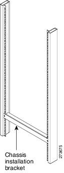
Each chassis is shipped with two chassis installation brackets in the accessory kit. These brackets are to aid in installing a chassis into a 19-inch rack and used as a support base to vertically position and set the chassis before the rack-mount screws are installed.
To install the chassis installation brackets into a rack, complete the following steps:
Step 1 Determine where in the rack you want the chassis to be mounted. If you are mounting more than one chassis in the rack, then start from the bottom up or the center of the rack. Install the chassis installation bracket where the chassis bottom will be positioned vertically in the rack.
Step 2 Secure the chassis installation bracket to the front rails with the rack-mount screws.
Step 3 If there is a second internal rack rail, which is not more than 20 inches from the front rail, you can position the second installation bracket to act as a rear support for the chassis during installation.
Figure 3-4 shows the brackets attached in a rack.
Figure 3-4 Chassis Installation Bracket

Note After the chassis is installed and secured to the rack, the chassis installation brackets can be removed from the rack. The brackets are not needed for supporting the chassis when all the rack-mount screws are installed.
Installing the Chassis Installation Handles
This section explains how to attach the chassis installation handles to the chassis.
Before installing the chassis in the rack, it is recommended that you install a chassis lifting handle to each side of the chassis to aid in lifting the chassis onto the rack.
Note It is recommended to install the two side chassis installation handles while unpacking to aid in moving the chassis off the palette.
The parts and tools required for installing the chassis installation handles are listed in the “Tools and Equipment” section.
Note Chassis installation handles should not be installed if the chassis is to be mid mounted.
To install the chassis installation handles on a Cisco RFGW-10 UEQAM, complete the following steps:
Step 1 Locate the two M5 threaded holes on the upper center of each side of the chassis that align with the handle captive screws. (See Figure 3-5.)
Step 2 Install the two chassis installation handles on either side of the chassis and tighten the captive screws.
Figure 3-5 Attaching the Chassis Installation Handles to the Cisco RFGW-10 UEQAM
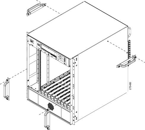
After the chassis rack-mount brackets are installed, additional handles can be installed onto the front of the rack-mount brackets. The rack-mount brackets allow a low and high installation of the handles onto the bracket depending on the chassis installation (low or high in the rack).
Attaching the Chassis Rack-Mount Brackets
This section explains how to attach the front and the mid rack-mount brackets to the chassis. Before installing the chassis in the rack, you must install the rack-mount brackets on each side of the chassis.
The parts and tools required for installing the rack-mount brackets, chassis installation handles, chassis installation bracket, and the cable management brackets are listed in the “Tools and Equipment” section.
Note The rear RF cable-management bracket is installed on the chassis after you install the chassis rack-mount brackets and mount the chassis in the rack.
Chassis Front Rack-Mount Brackets Installation
To install the front rack-mount brackets on a Cisco RFGW-10 UEQAM, complete the following steps:
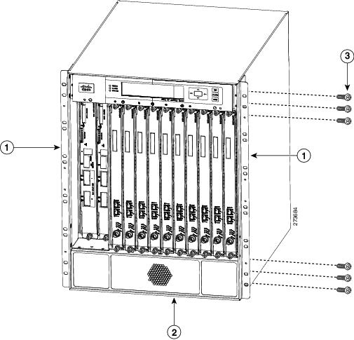
Step 1 Locate the threaded holes on the front sides of the chassis that align with the holes in the rack-mount bracket. Ensure that you hold the front rack-mount bracket with the ear and holes facing outward and towards the front of the chassis (see Figure 3-6).
Step 2 Install all six M5 undercut flat-head screws (provided in the accessory kit) to secure each of the rack-mounting bracket to the chassis. There will be three screws installed on each end of the rack-mounting bracket.
Step 3 Repeat Step 1 through Step 2 on the other side of the chassis.
Step 4 Install the chassis in the rack. To install the Cisco RFGW-10 UEQAM in the rack, go to “Installing the Cisco RFGW-10 UEQAM in a Rack” section.
Figure 3-6 Attaching the Front Rack-Mount Brackets
Chassis Mid-Mounted Rack-Mount Bracket Installation
If you are rack-mounting the chassis using a mid-mounted configuration, then it provides for the chassis being recessed in the rack or installed in a two-post rack.
Note Chassis installation handles cannot be installed if the chassis is to be mid-mounted.
To install the rack-mount brackets for a mid-mounted configuration on a Cisco RFGW-10 UEQAM, complete the following steps:
Step 1 Locate the threaded holes on the middle sides of the chassis that align with the holes in the rack-mount bracket. Ensure that you hold the front rack-mount bracket with the ear and holes facing outward and towards the rear of the chassis (see Figure 3-7).
Step 2 Install all the six M5 undercut flat-head screws (provided in the accessory kit) to secure each of the rack-mounting bracket to the chassis. There will be three screws installed on each end of the rack-mounting bracket.
Step 3 Repeat Step 1 through Step 2 on the other side of the chassis.
Step 4 Install the chassis in the rack. To install the Cisco RFGW-10 UEQAM in a rack, go to “Installing the Cisco RFGW-10 UEQAM in a Rack” section.
Figure 3-7 Attaching the Rack-Mount Brackets for Mid-Mount Configuration to the Cisco RFGW-10 Chassis

Installing the Cisco RFGW-10 UEQAM in a Rack
After installing the rack-mount brackets, the installation handles on the chassis, and the installation brackets in the rack, mount the chassis by securing the rack-mount brackets to the two posts or mounting strips in the rack. Because the rack-mount brackets supports the weight of the entire chassis, be sure to use at least four rack-mount screws on each side to fasten the two rack-mount brackets to the rack posts.
Warning To prevent bodily injury when mounting or servicing this unit in a rack, you must take special precautions to ensure that the system remains stable. The following guidelines are provided to ensure your safety:
- This unit should be mounted at the bottom of the rack if it is the only unit in the rack.
- When mounting this unit in a partially filled rack, load the rack from the bottom to the top with the heaviest component at the bottom of the rack.
- If the rack is provided with stabilizing devices, install the stabilizers before mounting or servicing the unit in the rack. Statement 1006
To install the chassis in the rack, complete the following steps:
Step 1 On the chassis, ensure that all the screw fasteners on the installed components are securely tightened.
Step 2 Ensure that your path to the rack is unobstructed. If the rack is on wheels, ensure that the brakes are engaged or that the rack is otherwise stabilized.
Step 3 (Optional) Install the chassis installation brackets into the rack to help support the chassis during installation (see Figure 3-4). If you use the brackets, this will help support the chassis while you secure it to the rack.
Step 4 With two people, lift the chassis (partially unloaded) into position between the rack posts and rest it on the chassis installation bracket (see Figure 3-8).
Figure 3-8 Positioning the Chassis on the Chassis Installation Bracket

Step 5 Remove the side chassis installation handles and slide the chassis into position in the rack.
Note If you have the chassis installation handles installed on the front rack-mount rails they can be used to aid in sliding the chassis into the rack. Additionally, the fan tray handles can be used during the rack installation process.
Step 6 Position the chassis until the rack-mounting flanges flush against the mounting rails on the rack (see Figure 3-9).
Figure 3-9 Positioning the Chassis on the Rack

Step 7 Hold the chassis in position against the mounting rails and follow these steps:
a. Insert a bottom screw into the rack-mount ear on each side and use a hand-held screwdriver to tighten the screw to the rack rail.

Tip In the next step, insert the top screw diagonally from the bottom screw that you just attached. This helps in keeping the chassis in place.
b. Insert a top screw into each side rack-mount bracket and tighten the screw to the rack rail.
c. Insert a minimum of four screws per bracket on both sides of the chassis.
Note If you are using the chassis installation handles on the front rack-mount brackets, you must first remove the handles to install the fourth screw.
Step 8 Ensure that all screws on each side rack-mount brackets are tightened to the equipment rack then the chassis installation brackets can be removed from the rack (see Figure 3-10).
Figure 3-10 Securing the Side Rack-Mount Brackets

You can install your Cisco RFGW-10 chassis in a two-post rack (see “Two-Post Rack Installation Mid-Mounted” section) or a four-post rack.
Two-Post Rack Installation Mid-Mounted
The Cisco RFGW-10 chassis can be installed in a two-post 19-inch rack either as a front mount or a mid-mount (see Figure 3-12).
Step 1 On the chassis, ensure that all the screw fasteners on the installed components are securely tightened.
Step 2 Ensure that your path to the rack is unobstructed. If the rack is on wheels, ensure that the brakes are engaged or that the rack is otherwise stabilized. See the section on the types of racks you can use to install the chassis.
Step 3 (Optional) Install the chassis installation bracket into the rack to help support the chassis during installation (see Figure 3-11). If you use the bracket, this will help support the chassis while you secure it to the rack.
Figure 3-11 Chassis Installation Bracket
Step 4 With two people, lift the chassis (partially unloaded) into position between the rack posts and rest it on the chassis installation bracket.
Step 5 Position the chassis until the rack-mounting flanges flush against the mounting rails on the rack.
Step 6 Hold the chassis in position against the mounting rails and follow these steps:
a. Insert a bottom screw into the rack-mount ear on each side and use a hand-held screwdriver to tighten the screw to the rack rail.
Tip In the next step, insert the top screw diagonally from the bottom screw that you just attached. This helps to keep the chassis in place.
b. Insert a top screw into each side rack-mount bracket and tighten the screw to the rack rail.
c. Insert a minimum of four screws per bracket on both sides of the chassis.
Figure 3-12 Installing the Cisco RFGW-10 in a Two-Post Equipment Rack

Step 7 Ensure that all the screws on each side of the rack-mount brackets are tightened to the equipment rack before the chassis installation bracket is removed from the rack.
This completes the procedure for installing the chassis in a two-post rack. Proceed to “Attaching a Chassis Ground Connection” section to continue the installation.
Attaching a Chassis Ground Connection
Connecting the Cisco RFGW-10 chassis to earth ground is required for all DC powered installations where compliance with NEBS grounding requirements is necessary.
The following are the tools, equipment, and supplies necessary to connect the system ground to the chassis:
- Phillips screwdriver
- 90 degree, 6 AWG wire, dual-lug chassis ground component (provided in the accessory kit)
- 6 AWG grounding wire
Have the recommended tools and supplies before you begin this procedure.
Figure 3-13 shows the Chassis NEBS grounding attached to the chassis in the lower left corner of the rear of the chassis.
Figure 3-13 Installing the Cisco RFGW-10 UEQAM Telcordia Ground Connection

Warning This equipment must be grounded. Never defeat the ground conductor or operate the equipment in the absence of a suitably installed ground conductor. Contact the appropriate electrical inspection authority or an electrician if you are uncertain that suitable grounding is available. Statement 1024
Before you connect the power or turn on the power to your chassis, you must provide an adequate chassis ground (earth) connection for the chassis. A chassis ground connector is provided on each Cisco RFGW-10 chassis. There is a dual ring stud on the rear lower left side of the chassis and on each DC power supply (primary grounding stud).
Use the following procedure to attach the grounding lug to the chassis ground connector on your chassis:
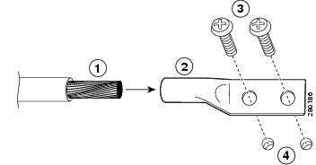
Step 1 Use the wire stripper to strip one end of the AWG #6 wire approximately 0.75 inches (19.05 mm).
Step 2 Insert the AWG #6 wire into the wire receptacle on the 90 degree grounding lug (see Figure 3-14).
Step 3 Use the crimping tool to carefully crimp the wire receptacle around the wire. This step is required to ensure a proper mechanical connection.
Step 4 Attach the grounding lug with the wire so that the grounding wire does not overlap the power supply.
Figure 3-14 90-Degree Grounding Lug

Figure 3-15 Rotating 90 Degree
Step 5 Locate the chassis ground connector on the rear lower left side of your chassis.
Step 6 Insert the two screws through the holes in the grounding lug M5 screws (provided in the accessory kit) until the grounding lug is held firmly to the chassis.
Step 7 Connect the opposite end of the grounding wire to the appropriate grounding point at your site to ensure an adequate chassis ground.
Attaching the Cable-Management Bracket
The rear RF cable-management brackets mount to the rear left side of the chassis to provide cable-management to coaxial cables exiting the RF switch modules. This bracket allows reference configuration that allows installation and removal of cables and modules in the rear of the chassis.
The RF cable-management bracket for the Cisco RFGW-10 UEQAM contains 12 independent cable-management “U” type features with three captive screws for attaching to the chassis, and provides cable dressing of each RF switch card module slot. (See Figure 3-16.)
Figure 3-16 Cable-Management Bracket

Follow these steps to attach the cable-management brackets to the rear sides of the Cisco RFGW-10 chassis in the rack:
Step 1 Align the cable-management bracket captive screws to the rear left side panel tapped holes of the Cisco RFGW-10 chassis.
Step 2 If accessible, use a Phillips screwdriver to secure the captive screws to the chassis. If the captive screws are not accessible, hand tighten the captive screws.
Note Do not overtighten the cable management captive screws when using a Phillips screwdriver. Tighten to 5-in lbs torque maximum.
Figure 3-17 shows the cable-management brackets attached to the chassis.
Figure 3-17 Installing the Cable-Management Bracket

Connecting Power to Cisco RFGW-10 UEQAM
Warning The covers are an integral part of the safety design of the product. Do not operate the unit without the covers installed. Statement 1077
Warning When you install the unit, the ground connection must always be made first and disconnected last. Statement 1046
Warning Before performing any of the following procedures, ensure that power is removed from the DC circuit. Statement 1003
Warning Only trained and qualified personnel should be allowed to install, replace, or service this equipment. Statement 1030
This section provides the procedures for connecting the DC-input power to your Cisco RFGW-10 UEQAM.
Table 3-1 shows the common input range and circuit breaker requirements.
Table 3-1 Cisco RFGW-10 UEQAM DC PEM System Input Requirements
Note Both DC inputs to the DC PEM must be connected and energized for the Cisco RFGW-10 system to operate properly.
Note Detailed instructions for removing and replacing the Cisco RFGW-10 DC PEM are in “Installation and Removal of the DC PEM” section.
Connecting DC-Input Power to Cisco RFGW-10 UEQAM
This section describes how to connect the DC power supply to the Cisco RFGW-10 UEQAM.
Before you begin, read these important notices:
- The color coding of the DC-input power supply leads depends on the color coding of the DC power source at your site. Typically, green or green/yellow is used for ground (GND), black is used for –48V on negative (–) terminal and red is used for RTN on the positive (+) terminal. Ensure that the lead color coding you choose for the DC-input power supply matches the lead color coding used at the DC power source.
- For the DC input power cables, select the appropriate wire gauge based on the National Electrical Code (NEC) and the local codes for 60-amp service at nominal DC input voltage (–48 VDC). Two pairs of cable leads, source DC (–) and source DC return (+), are required for each power distribution unit (PDU). These cables are available from any commercial cable vendor. All input power cables for the chassis should have the same wire gauge and cable lengths should match within 10 percent of deviation.
Each DC input power cable is terminated at the PDU by a cable lug (included in the accessory kit). The cable lugs must be dual-hole, and have a 90 degree tongue (reference Panduit LCD4-14AF-L). They must be able to fit over M6 terminal studs at 0.625-inch (15.88-mm) centers.
Note The DC input power cables must be connected to the PDU terminal studs in the proper positive (+) and negative (–) polarity. In some cases, the DC cable leads are labeled, which is a relatively safe indication of the polarity. However, you must verify the polarity by measuring the voltage between the DC cable leads. When making the measurement, the positive (+) lead and the negative (–) lead must always match the (+) and (–) labels on the power distribution unit.
- An earth ground cable is required for each DC PDU. We recommend that you use at least 4-AWG multi-strand copper wire. This wire is not available from Cisco; it is available from any commercial cable vendor.
The ground wire cable lug (provided in the accessory kit) should be dual-hole (as shown in Figure 3-18), 90 degree tongue (reference Panduit LCD4-14AF-L), and able to fit over M6 terminal studs at 0.625 inch (1.588 cm) centers.
Figure 3-18 DC Input Power Cable Lug Example

Note To avoid hazardous conditions, all components in the area where DC input power is accessible must be properly insulated. Therefore, before installing the DC cable lugs, be sure to insulate the lugs according to the manufacturer's instructions.
Note Detailed instructions for removing and replacing the Cisco RFGW-10 UEQAM DC PEM are in “Installation and Removal of the DC PEM” section.
To connect the DC PEM, follow these steps:
Note Make sure that the facility input power is removed safely from the power cables before and during wiring of the input power cables.
Step 1 Make certain that the chassis grounding is connected before you begin installing the DC PEM.
Step 2 Ensure that the DC PEM is disconnected from the chassis midplane power connector and that the power supply breaker is in the off position.
Step 3 Locate the stud on the DC PEM for the GND connection, which must be connected first and follow these steps:
a. Using the provided grounding lug in the accessory kit, replace the washers and Kepnut screw in the following order:
b. Tighten the Kepnut screws on the power supply studs to the recommended torque of 18 in-lbs minimum to 22 in-lbs maximum.
Figure 3-19 Cisco RFGW-10 DC PEM

Note To meet the electromagnetic interference (EMI) requirements, the DC power supply should be removed from the chassis if the PEM has failed or the circuit breaker is off.
Step 4 Attach the other end of the cable to the site ground connection.
Step 5 Remove or rotate the plastic cover from the terminal block.
Step 6 You must wrap the positive and the negative lead cables with the sleeves. Take each lead wire and cover the area from the lug to the wire with heavy shrink sleeve.
Step 7 Insert the negative lead cable first. Replace the ground lug with cable in the following order:
b. Ground lug with negative wire
Step 8 Tighten the Kepnut screw to the recommended torque of 18 in-lbs minimum to 22 in-lbs maximum.
Step 9 Repeat Step 6 through Step 8 for the RTN lead cable.
Note Secure the wires coming in from the terminal block so that they cannot be disturbed by casual contact.
Step 10 Replace and rotate the terminal block plastic cover back into position until it is locked.
Figure 3-20 Cisco RFGW-10 DC PEM Terminal Block Plastic Cover

Step 11 Repeat steps 6 through 10 for the second DC input feed to the PEM.
Note Both DC inputs to the DC PEM must be connected and energized for the RFGW-10 system to operate properly.
Step 12 Fully install the DC PEM into the power supply bay and tighten the captive fasteners on the faceplate to the chassis.
Note Tighten the DC PEM captive fasteners to 12-16 in-lb torque.
Note Both DC inputs to the DC PEM must be connected and energized for the Cisco RFGW-10 UEQAM system to operate properly.
Powering On the Cisco RFGW-10 UEQAM
Step 1 Energize the facility DC power feeds to the power supply.
Step 2 Verify power supply operation by checking the DC PEM’s front panel LEDs. The –48 V1 and –48 V2 LEDs should illuminate green.
Step 3 Switch the circuit breaker switch to the On (|) position.
Step 4 Again verify the power supply operation by checking the power supply’s front panel LEDs. The –48 V1, –48 V2 and OUTPUT OK LEDs should illuminate green.
Step 5 Check the power supply and system status from the system console using the show power ? command. For more information on the commands, refer to the command reference publication for your chassis and software.
Connecting the Lineage Power Shelf to the Cisco RFGW-10
The Lineage power shelves are used with the DC PEM modules on the Cisco RFGW-10. Two configurations are supported on the Cisco RFGW-10. For specifications, see System Specifications.
The following sections describe how to connect the Lineage AC-DC power shelf to the Cisco RFGW-10:
- Cabling the Power Shelf
- Connecting a Single Power Shelf
- Connecting Dual Power Shelves
- Disconnecting Cables from the Power Shelf
Steps
Warning Before performing any of the following procedures, ensure that power is removed from the DC circuit. Statement 1003
To attach the cables to Lineage power shelf:
Step 1 Open the safety covers from above the DC terminal blocks by pushing the safety cover up and off the DC power terminal blocks on the power shelf.
Step 2 Loosen and remove the M6 nuts on the DC terminal blocks.
Step 3 Connect the DC power cables by attaching the lugged ends of cables to the DC power terminal blocks on the shelf. Secure the cables with the M6 nuts using a 10 mm hex socket driver with an installation torque of 45-in lbs. (See Figure 3-21.)
Figure 3-21 Y-Shaped DC Power Cable with Lugged Ends

Step 4 Place the safety covers on the DC terminal blocks.
Step 5 Proceed to connecting the Lineage power shelf to the Cisco RFGW-10 chassis.
- Single Lineage power shelf configuration—If you are using this configuration, see “Connecting a Single Power Shelf” section.
- Dual Lineage power shelves configuration—If you are using this configuration, see “Connecting Dual Power Shelves” section.
Step 6 Connect the de-energized AC power cables to the power shelf.
Step 7 Connect the AC power cables to the facility wall socket to energize the power shelf.
Required Tools and Equipment
- DC PEM module (RFGW-10-PWR-DC1=)
- One Lineage AC-DC power shelf
- Four Y power cables (Amphenol), provided in the Lineage accessory kit
- Flat-head screwdriver
- 10 mm hex socket driver
Note It is recommend that you use the Y-Shaped DC power cables provided in the Lineage accessory kit. If you are using a 4 AWG cable, use a high-flex high strand count power cable for optimal routing of the cables under the front cover of the Cisco RFGW-10 chassis. The 2 AWG wire is not supported on the RFGW-10-PWR-DC1= DC PEM module.
Steps
To connect a single power shelf to the DC PEM modules on the Cisco RFGW-10:
Step 1 Connect the Y-Shaped DC power cables to the Lineage power shelf, see the “Cabling the Power Shelf” section.
Step 2 Connect the DC power cables to the DC-input terminals on the Cisco RFGW-10 UEQAM. For information on connecting the DC power cables to the Cisco RFGW-10, see the “Connecting DC-Input Power to Cisco RFGW-10 UEQAM” section.
Step 3 Connect the AC power cables to a standard wall socket (facility power source) to provide power to the Cisco RFGW-10. See the “Powering On the Cisco RFGW-10 UEQAM” section.
Figure 3-22 shows the Lineage power shelf connected to the DC PEM modules.
Figure 3-22 Lineage Power Shelf Connected to DC PEM Modules - Configuration 1

Black Y-Shaped DC power cables from power shelf to RTN terminals DC PEM modules |
|||
Red Y-Shaped DC power cables from power shelf to –48 V terminals on DC PEM modules |
Required Tools and Equipment
- DC PEM module (RFGW-10-PWR-DC1=)
- Two Lineage AC-DC power shelves
- Eight straight DC power cables (Elmech), provided in the Lineage accessory kit
- Flat-screw driver
- 10 mm hex socket driver
Note It is recommend that you use the straight DC power cables provided in the Lineage accessory kit. If you are using a 4 AWG cable, use a high-flex high strand count power cable for optimal routing of the cables under the front cover of the Cisco RFGW-10. The 2 AWG wire is not supported on the RFGW-10-PWR-DC1= DC PEM module.
Steps
Step 1 Connect the cables to the two Lineage power shelves, see “Cabling the Power Shelf” section.
Step 2 Connect the DC “straight” power cables to the DC-input terminals on the on the Cisco RFGW-10 UEQAM. For information on connecting the cables, see “Cabling the Power Shelf” section.
Step 3 Connect the AC power cables to a standard wall socket (facility power source) to provide power to the Cisco RFGW-10 UEQAM. See “Powering On the Cisco RFGW-10 UEQAM” section.
Figure 3-23 shows two Lineage power shelves connected to the DC PEM modules.
Figure 3-23 Lineage Power Shelf Connected to DC PEM Modules - Configuration 2

Steps
To disconnect cables from the Lineage power shelf and the Cisco RFGW-10:
Step 1 Power off the power shelf by disconnecting the power supply at the facility. Wait a few minutes before disconnecting the power cables so that they discharge.
Step 2 Disconnect the AC cables from the standard wall socket. Disconnect the AC power cables from each of the AC-input power supply sources on the power shelf.
Step 3 Disconnect the DC power cables on each side of the DC power sources, on the power shelf.
Step 4 Disconnect the other ends of the DC power cable from the DC power terminal blocks of the Cisco RFGW-10.
 Feedback