
 Feedback
Contents
- IP SLAs TWAMP Responder
- Finding Feature Information
- Prerequisites for IP SLAs TWAMP Responder
- Restrictions for IP SLAs TWAMP Responder
- Information About IP SLAs TWAMP Responder
- TWAMP
- IP SLAs TWAMP Responder v1.0
- How to Configure an IP SLAs TWAMP Responder
- Configuring the TWAMP Server
- Configuring the Session-Reflector
- Configuration Examples for IP SLAs TWAMP Responder
- IP SLAs TWAMP Responder v1.0 Example
- Additional References
- Feature Information for IP SLAs TWAMP Responder
IP SLAs TWAMP Responder
This module describes how to configure an IETF Two-Way Active Measurement Protocol (TWAMP) responder on a Cisco device to measure IP performance between the Cisco device and a non-Cisco TWAMP control device on your network.
- Finding Feature Information
- Prerequisites for IP SLAs TWAMP Responder
- Restrictions for IP SLAs TWAMP Responder
- Information About IP SLAs TWAMP Responder
- How to Configure an IP SLAs TWAMP Responder
- Configuration Examples for IP SLAs TWAMP Responder
- Additional References
- Feature Information for IP SLAs TWAMP Responder
Finding Feature Information
Your software release may not support all the features documented in this module. For the latest caveats and feature information, see Bug Search Tool and the release notes for your platform and software release. To find information about the features documented in this module, and to see a list of the releases in which each feature is supported, see the feature information table at the end of this module.
Use Cisco Feature Navigator to find information about platform support and Cisco software image support. To access Cisco Feature Navigator, go to www.cisco.com/go/cfn. An account on Cisco.com is not required.
Information About IP SLAs TWAMP Responder
TWAMP
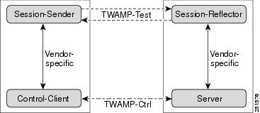
The IETF Two-Way Active Measurement Protocol (TWAMP) defines a standard for measuring round-trip network performance between any two devices that support the TWAMP protocols. The TWAMP-Control protocol is used to set up performance measurement sessions. The TWAMP-Test protocol is used to send and receive performance-measurement probes.
- The control-client sets up, starts, and stops TWAMP-Test sessions.
- The session-sender instantiates TWAMP-Test packets that are sent to the session-reflector.
- The session-reflector reflects a measurement packet upon receiving a TWAMP-Test packet. The session reflector does not collect packet statistics in TWAMP.
- The TWAMP server is an end system that manages one or more TWAMP sessions and is also capable of configuring per-session ports in the end points. The server listens on the TCP port. The session-refector and server make up the TWAMP responder in an IP SLAs operation.
Although TWAMP defines the different entities for flexibility, it also allows for logical merging of the roles on a single device for ease of implementation. The figure below shows the four entities that make up the TWAMP architecture.
IP SLAs TWAMP Responder v1.0
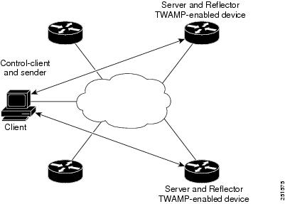
A TWAMP responder interoperates with the control-client and session-sender on another device that supports TWAMP. In the IP SLAs TWAMP Responder v1.0 feature, the session-reflector and TWAMP server that make up the responder must be co-located on the same device.
In the figure below, one device is the control-client and session-sender (TWAMP control device), and the other two devices are Cisco devices that are configured as IP SLAs TWAMP responders. Each IP SLAs TWAMP responder is both a TWAMP server and a session-reflector.
How to Configure an IP SLAs TWAMP Responder
Configuring the TWAMP Server
 Note | For IP SLAs TWAMP Responder v1.0, the TWAMP server and the session-reflector are configured on the same device. |
DETAILED STEPS
Configuring the Session-Reflector
Note | For IP SLAs TWAMP Responder v1.0, the TWAMP server and the session-reflector are configured on the same device. |
DETAILED STEPS
Configuration Examples for IP SLAs TWAMP Responder
IP SLAs TWAMP Responder v1.0 Example
Note | In order for the IP SLAs TWAMP responder to function, a control-client and the session-sender must be configured in your network. |
Device> enable
Device# configure terminal
Device(config)#  ip sla server twamp
Device(config-twamp-srvr)#  exit
Device(config)#  ip sla responder twamp
Device(config-twamp-ref)# end
Device> show running-config
.
.
.
ip sla responder
ip sla responder twamp
ip sla server twamp
port 12
Additional References
Technical Assistance
| Description | Link |
|---|---|
|
The Cisco Support and Documentation website provides online resources to download documentation, software, and tools. Use these resources to install and configure the software and to troubleshoot and resolve technical issues with Cisco products and technologies. Access to most tools on the Cisco Support and Documentation website requires a Cisco.com user ID and password. |
Feature Information for IP SLAs TWAMP Responder
The following table provides release information about the feature or features described in this module. This table lists only the software release that introduced support for a given feature in a given software release train. Unless noted otherwise, subsequent releases of that software release train also support that feature.
Use Cisco Feature Navigator to find information about platform support and Cisco software image support. To access Cisco Feature Navigator, go to www.cisco.com/go/cfn. An account on Cisco.com is not required.
| Table 1 | Feature Information for IP SLAs TWAMP Responder |
| Feature Name | Releases | Feature Information |
|---|---|---|
|
IP SLAs TWAMP Responder v1.0 |
15.2(2)S Cisco IOS XE Release 3.6S 15.2(3)T |
This feature enables you to configure the TWAMP server and the session-reflector on a Cisco device for measuring the round-trip performance between an IP SLAs TWAMP responder and a non-Cisco TWAMP control device in your network. The following commands were introduced or modified: ip sla responder twamp, ip sla server twamp, port (twamp), show ip sla standards, show ip sla twamp connection, show ip sla twamp session, show ip sla twamp standards, timer inactivity, timeout (twamp).. |
Cisco and the Cisco logo are trademarks or registered trademarks of Cisco and/or its affiliates in the U.S. and other countries. To view a list of Cisco trademarks, go to this URL: www.cisco.com/go/trademarks. Third-party trademarks mentioned are the property of their respective owners. The use of the word partner does not imply a partnership relationship between Cisco and any other company. (1110R)
Any Internet Protocol (IP) addresses and phone numbers used in this document are not intended to be actual addresses and phone numbers. Any examples, command display output, network topology diagrams, and other figures included in the document are shown for illustrative purposes only. Any use of actual IP addresses or phone numbers in illustrative content is unintentional and coincidental.