
 Feedback
Contents
- MPLS VPN--L3VPN over GRE
- Finding Feature Information
- Prerequisites for MPLS VPN--L3VPN over GRE
- Restrictions for MPLS VPN--L3VPN over GRE
- Information About MPLS VPN--L3VPN over GRE
- Overview of MPLS VPN-L3VPN over GRE
- PE-to-PE Tunneling
- P-to-PE Tunneling
- P-to-P Tunneling
- How to Configure MPLS VPN--L3VPN over GRE
- Configuring the MPLS VPN--L3VPN over GRE Tunnel Interface
- Example: Configuring a GRE Tunnel that spans a non-MPLS Network
- Configuration Examples for MPLS VPN--L3VPN over GRE
- Example: MPLS Configuration with MPLS VPN--L3VPN over GRE
- Additional References
- Feature Information for MPLS VPN--L3VPN over GRE
MPLS VPN--L3VPN over GRE
The MPLS VPN--L3VPN over GRE feature provides a mechanism for tunneling Multiprotocol Label Switching (MPLS) packets over a non-MPLS network. This feature utilizes MPLS over generic routing encapsulation (MPLSoGRE) to encapsulate MPLS packets inside IP tunnels. The encapsulation of MPLS packets inside IP tunnels creates a virtual point-to-point link across non-MPLS networks.
- Finding Feature Information
- Prerequisites for MPLS VPN--L3VPN over GRE
- Restrictions for MPLS VPN--L3VPN over GRE
- Information About MPLS VPN--L3VPN over GRE
- How to Configure MPLS VPN--L3VPN over GRE
- Configuration Examples for MPLS VPN--L3VPN over GRE
- Additional References
- Feature Information for MPLS VPN--L3VPN over GRE
Finding Feature Information
Your software release may not support all the features documented in this module. For the latest caveats and feature information, see Bug Search Tool and the release notes for your platform and software release. To find information about the features documented in this module, and to see a list of the releases in which each feature is supported, see the feature information table at the end of this module.
Use Cisco Feature Navigator to find information about platform support and Cisco software image support. To access Cisco Feature Navigator, go to www.cisco.com/go/cfn. An account on Cisco.com is not required.
Prerequisites for MPLS VPN--L3VPN over GRE
- Before you configure the MPLS VPN--L3VPN over GRE feature, ensure that your MPLS virtual private network (VPN) is configured and working properly. See the Configuring MPLS Layer 3 VPNs module for information about setting up MPLS VPNs.
- For PE-to-PE tunneling, configure tunnels with the same source address if you are running a release earlier than Cisco IOS Release 15.2(1)S.
- For PE-to-PE tunneling, configure tunnels with the same destination address.
- Ensure that the following routing protocols are configured and working properly:
Restrictions for MPLS VPN--L3VPN over GRE
Information About MPLS VPN--L3VPN over GRE
Overview of MPLS VPN-L3VPN over GRE
The MPLS VPN--L3VPN over GRE feature provides a mechanism for tunneling MPLS packets over non-MPLS networks. This feature allows you to create a GRE tunnel across a non-MPLS network. The MPLS packets are encapsulated within the GRE tunnel packets, and the encapsulated packets traverse the non-MPLS network through the GRE tunnel. When GRE tunnel packets are received at the other side of the non-MPLS network, the GRE tunnel packet header is removed and the inner MPLS packet is forwarded to its final destination.
PE-to-PE Tunneling
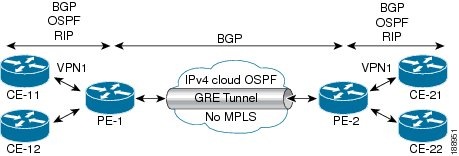
The provider-edge-to-provider-edge (PE-to-PE) tunneling configuration provides a scalable way to connect multiple customer networks across a non-MPLS network. With this configuration, traffic that is destined to multiple customer networks is multiplexed through a single GRE tunnel.
 Note | A similar nonscalable alternative is to connect each customer network through separate GRE tunnels (for example, connecting one customer network to each GRE tunnel). |
As shown in the figure below, the PE devices assign VPN routing and forwarding (VRF) numbers to the customer edge (CE) devices on each side of the non-MPLS network.
The PE devices use routing protocols such as Border Gateway Protocol (BGP), Open Shortest Path First (OSPF), or Routing Information Protocol (RIP) to learn about the IP networks behind the CE devices. The routes to the IP networks behind the CE devices are stored in the associated CE device's VRF routing table.
The PE device on one side of the non-MPLS network uses the routing protocols (that operate within the non-MPLS network) to learn about the PE device on the other side of the non-MPLS network. The learned routes that are established between the PE devices are then stored in the main or default routing table.
The opposing PE device uses BGP to learn about the routes that are associated with the customer networks that are behind the PE devices. These learned routes are not known to the non-MPLS network.
The following figure shows BGP defining a static route to the BGP neighbor (the opposing PE device) through the GRE tunnel that spans the non-MPLS network. Because routes that are learned by the BGP neighbor include the GRE tunnel next hop, all customer network traffic is sent using the GRE tunnel.
P-to-PE Tunneling
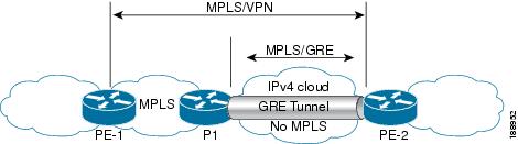
As shown in the figure below, the provider-to-provider-edge (P-to-PE) tunneling configuration provides a way to connect a PE device (P1) to an MPLS segment (PE-2) across a non-MPLS network. In this configuration, MPLS traffic that is destined to the other side of the non-MPLS network is sent through a single GRE tunnel.
P-to-P Tunneling
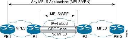
As shown in the figure below, the provider-to-provider (P-to-P) configuration provides a method of connecting two MPLS segments (P1 to P2) across a non-MPLS network. In this configuration, MPLS traffic that is destined to the other side of the non-MPLS network is sent through a single GRE tunnel.
How to Configure MPLS VPN--L3VPN over GRE
Configuring the MPLS VPN--L3VPN over GRE Tunnel Interface
To configure the MPLS VPN--L3VPN over GRE feature, you must create a GRE tunnel to span the non-MPLS networks. You must perform the following procedure on the devices located at both ends of the GRE tunnel.
DETAILED STEPS
Example: Configuring a GRE Tunnel that spans a non-MPLS Network
The following example shows a GRE tunnel configuration that spans a non-MPLS network. This example shows the tunnel configuration on the PE devices (PE1 and PE2) located at both ends of the tunnel:
Configuration Examples for MPLS VPN--L3VPN over GRE
Example: MPLS Configuration with MPLS VPN--L3VPN over GRE
The following basic MPLS configuration example uses a GRE tunnel to span a non-MPLS network. This example is similar to the configuration shown in the first figure above.
PE1 Configuration
!
mpls ip
!
ip vrf vpn1
rd 100:1
route-target import 100:1
route-target export 100:1
!
 interface loopback 0
 ip address 10.2.2.2 255.255.255.255
!
 interface GigabitEthernet 0/1/2
 ip address 10.1.1.1 255.255.255.0
!
 interface Tunnel 1
 ip address 10.0.0.1 255.255.255.0
 tunnel source 10.1.1.1
 tunnel destination 10.1.1.2
 mpls ip
!
 interface GigabitEthernet 0/1/3
 ip vrf forwarding vpn1
 ip address 10.10.0.1 255.255.255.0
!
router bgp 100
neighbor 10.5.5.5 remote-as 100
neighbor 10.5.5.5 update-source loopback0
!
address-family vpnv4
neighbor 10.5.5.5 activate
neighbor 10.5.5.5 send community-extended
!
address-family ipv4 vrf vpn1
neighbor 10.10.0.2 remote-as 20
neighbor 10.10.0.2 activate
!
PE2 Configuration
!
mpls ip
!
ip vrf vpn1
rd 100:1
route-target import 100:1
route-target export 100:1
!
 interface loopback 0
 ip address 10.5.5.5 255.255.255.255
!
 interface GigabitEthernet 0/1/1
 ip address 10.1.1.2 255.255.255.0
!
 interface Tunnel 1
 ip address 10.0.0.2 255.255.255.0
 tunnel source 10.1.1.2
 tunnel destination 10.1.1.1
 mpls ip
!
 interface GigabitEthernet 0/0/5
 ip vrf forwarding vpn1
 ip address 10.1.2.1 255.255.255.0
!
router bgp 100
neighbor 10.2.2.2 remote-as 100
neighbor 10.2.2.2 update-source loopback0
!
address-family vpnv4
neighbor 10.2.2.2 activate
neighbor 10.2.2.2 send community-extended
!
address-family ipv4 vrf vpn1
neighbor 10.1.2.2 remote-as 30
neighbor 10.1.2.2 activate
!
Additional References
Related Documents
|
Related Topic |
Document Title |
|---|---|
|
Cisco IOS commands |
|
|
Multiprotocol Label Switching (MPLS) commands |
|
|
Setting up MPLS VPN networks Multiprotocol Border Gateway Protocol (MP-BGP) |
Configuring MPLS Layer 3 VPNs |
|
Label Distribution Protocol |
MPLS Label Distribution Protocol Overview |
|
Configuring L3 VPN over mGRE tunnels |
Dynamic Layer-3 VPNs with Multipoint GRE Tunnels |
Technical Assistance
|
Description |
Link |
|---|---|
|
The Cisco Support and Documentation website provides online resources to download documentation, software, and tools. Use these resources to install and configure the software and to troubleshoot and resolve technical issues with Cisco products and technologies. Access to most tools on the Cisco Support and Documentation website requires a Cisco.com user ID and password. |
Feature Information for MPLS VPN--L3VPN over GRE
The following table provides release information about the feature or features described in this module. This table lists only the software release that introduced support for a given feature in a given software release train. Unless noted otherwise, subsequent releases of that software release train also support that feature.
Use Cisco Feature Navigator to find information about platform support and Cisco software image support. To access Cisco Feature Navigator, go to www.cisco.com/go/cfn. An account on Cisco.com is not required.
| Table 1 | Feature Information for MPLS VPN--L3VPN over GRE |
|
Feature Name |
Releases |
Feature Information |
|---|---|---|
|
MPLS VPN--L3VPN over GRE feature |
12.0(22)S 12.0(26)S 12.2(33)SRE 15.2(1)S 15.2(4)S 12.2(13)T |
The MPLS VPN--L3VPN over GRE feature provides a mechanism for tunneling Multiprotocol Label Switching (MPLS) packets over a non-MPLS network. Depending on your release, you can configure tunnels with the same source address in a PE-to-PE tunneling configuration. |
Cisco and the Cisco logo are trademarks or registered trademarks of Cisco and/or its affiliates in the U.S. and other countries. To view a list of Cisco trademarks, go to this URL: www.cisco.com/go/trademarks. Third-party trademarks mentioned are the property of their respective owners. The use of the word partner does not imply a partnership relationship between Cisco and any other company. (1110R)
Any Internet Protocol (IP) addresses and phone numbers used in this document are not intended to be actual addresses and phone numbers. Any examples, command display output, network topology diagrams, and other figures included in the document are shown for illustrative purposes only. Any use of actual IP addresses or phone numbers in illustrative content is unintentional and coincidental.