Guest

Support

Configuring NAT for IP Address Conservation

  • Viewing Options

  • PDF (661.1 KB)
  • Feedback
Configuring NAT for IP Address Conservation

Table Of Contents

Configuring NAT for IP Address Conservation

Contents

Prerequisites for Configuring NAT for IP Address Conservation

Restrictions for Configuring NAT for IP Address Conservation

Information About Configuring NAT for IP Address Conservation

Benefits of Configuring NAT for IP Address Conservation

Purpose of NAT

How NAT Works

Uses of NAT

NAT Inside and Outside Addresses

Types of NAT

How to Configure NAT for IP Address Conservation

Configuring the Inside Source Addresses

Inside Source Address Translation

Configuring Static Translation of Inside Source Addresses

Configuring Dynamic Translation of Inside Source Addresses

Allowing Internal Users Access to the Internet Using NAT

Inside Global Addresses Overloading

Configuring Address Translation Timeouts

Changing the Translation Timeout Default

Changing the Default Timeouts When Overloading Is Configured

Allowing Overlapping Networks to Communicate Using NAT

Address Translation of Overlapping Networks

Configuring Static Translation of Overlapping Networks

What to Do Next

Configuring Dynamic Translation of Overlapping Networks

Configuring the NAT Virtual Interface

NAT Virtual Interface Design

Benefits of NAT Virtual Interface

Restrictions for NAT Virtual Interface

Enabling a Dynamic NAT Virtual Interface

Enabling a Static NAT Virtual Interface

Avoiding Server Overload Using TCP Load Balancing

TCP Load Distribution for NAT

Using Route Maps for Address Translation Decisions

Benefits of Using Route Maps For Address Translation

Prerequisites

Enabling NAT Routemaps Outside-to-Inside Support

Routemaps Outside-to-Inside Support Design

Restrictions

Configuring NAT of External IP Addresses Only

Benefits of Configuring NAT of External IP Addresses Only

Configuring NAT for a Default Inside Server

Restrictions

Configuring NAT RTSP Support Using NBAR

Configuring Support for Users with Static IP Addresses

Public Wireless LAN

RADIUS

Prerequisites

Configuring Static IP Support

Verifying Static IP Support

Configuring Support for ARP Ping in a Public Wireless LAN

Limiting the Number of Concurrent NAT Operations

Benefits of Limiting the Number of concurrent NAT Operations

Denial-of-Service Attacks

Viruses and Worms That Target NAT

Prerequisites

Configuration Examples for Configuring NAT for IP Address Conservation

Configuring Static Translation of Inside Source Addresses: Examples

Configuring Dynamic Translation of Inside Source Addresses: Example

Overloading Inside Global Addresses: Example

Translating Overlapping Address: Example

Enabling NAT Virtual Interface: Example

Avoiding Server Overload Using Load Balancing: Example

Enabling NAT Route Mapping: Example

Enabling NAT Routemaps Outside-to-Inside Support: Example

Configuring NAT Translation of External IP Addresses Only: Example

Configuration Examples for NAT Static IP Support

Configuring NAT Static IP Support: Example

Creating a RADIUS Profile for NAT Static IP Support: Example

Configuration Examples for Rate Limiting NAT Translation

Setting a Global NAT Rate Limit: Example

Setting NAT Rate Limits for a Specific VRF Instance: Example

Setting NAT Rate Limits for All VRF Instances: Example

Setting NAT Rate Limits for Access Control Lists: Example

Setting NAT Rate Limits for an IP Address: Example

Where to Go Next

Additional References

Related Documents

Standards

MIBs

RFCs

Technical Assistance

Feature Information for Configuring NAT for IP Address Conservation


Configuring NAT for IP Address Conservation


NAT enables private IP internetworks that use nonregistered IP addresses to connect to the Internet. NAT operates on a router, usually connecting two networks together, and translates the private (not globally unique) address in the internal network into legal addresses before packets are forwarded onto another network. NAT can be configured to advertise only one address for the entire network to the outside world. This ability provides additional security, effectively hiding the entire internal network behind that one address.

NAT is also used at the Enterprise edge to allow internal users access to the Internet and to allow Internet access to internal devices such as mail servers.

Module History

This module was first published on May 2, 2005, and was last updated on February 27, 2006.

Finding Feature Information in This Module

Your Cisco IOS software release may not support all features. To find information about feature support and configuration, use the "Feature Information for Configuring NAT for IP Address Conservation" section.

Contents

Prerequisites for Configuring NAT for IP Address Conservation

Restrictions for Configuring NAT for IP Address Conservation

Information About Configuring NAT for IP Address Conservation

How to Configure NAT for IP Address Conservation

Configuration Examples for Configuring NAT for IP Address Conservation

Where to Go Next

Additional References

Feature Information for Configuring NAT for IP Address Conservation

Prerequisites for Configuring NAT for IP Address Conservation

Access Lists

All access lists required for use with the tasks in this module should be configured prior to beginning the configuration task. For information about how to configure an access list, refer to the IP Access List Sequence Numbering document at the following URL:

http://www.cisco.com/univercd/cc/td/doc/product/software/ios122s/122snwft/release/122s14/fsaclseq.htm


Note If you specify an access list to use with a NAT command, NAT does not support the commonly used permit ip any any command in the access list.


Defining the NAT Requirements, Objectives, and Interfaces

Before configuring NAT in your network, it is important to understand on which interfaces NAT will be configured and for what purposes. You can use the questions below to determine how you will use NAT and how NAT will need to be configured.

1. Define NAT inside and outside interfaces by answering the following questions:

Do users exist off multiple interfaces?

Are there multiple interfaces going to the Internet?

2. Define what is trying to be accomplished with NAT by answering the following questions:

Should NAT allow internal users to access the Internet?

Should NAT allow the Internet to access internal devices such as a mail server?

Should NAT redirect TCP traffic to another TCP port or address?

Will NAT be used during a network transition?

Should NAT allow overlapping networks to communicate?

Should NAT allow networks with different address schemes to communicate?

Should NAT allow the use of an application level gateway?

Restrictions for Configuring NAT for IP Address Conservation

NAT is not practical if large numbers of hosts in the stub domain communicate outside of the domain.

Some applications use embedded IP addresses in such a way that it is impractical for a NAT device to translate them. These applications may not work transparently or at all through a NAT device.

NAT also hides the identity of hosts, which may be an advantage or a disadvantage depending on the desired result.

A router configured with NAT must not advertise the local networks to the outside. However, routing information that NAT receives from the outside can be advertised in the stub domain as usual.

If you specify an access list to use with a NAT command, NAT does not support the commonly used permit ip any any command in the access list.

Information About Configuring NAT for IP Address Conservation

To configure NAT for IP address conservation, you should understand the following concepts:

Benefits of Configuring NAT for IP Address Conservation

Purpose of NAT

How NAT Works

Uses of NAT

NAT Inside and Outside Addresses

Types of NAT

Benefits of Configuring NAT for IP Address Conservation

NAT allows organizations to resolve the problem of IP address depletion when they have existing networks and need to access the Internet. Sites that do not yet possess NIC-registered IP addresses must acquire them, and if more than 254 clients are present or planned, the scarcity of Class B addresses becomes a serious issue. Cisco IOS NAT addresses these issued by mapping thousands of hidden internal addresses to a range of easy-to-get Class C addresses.

Sites that already have registered IP addresses for clients on an internal network may want to hide those addresses from the Internet so that hackers cannot directly attack the clients. With client addresses hidden, a degree of security is established. Cisco IOS NAT gives LAN administrators complete freedom to expand Class A addressing, which is drawn from the reserve pool of the Internet Assigned Numbers Authority (RFC 1597). This expansion occurs within the organization without concern for addressing changes at the LAN/Internet interface.

Cisco IOS can selectively or dynamically perform NAT. This flexibility allows the network administrator to use a mix of RFC 1597 and RFC 1918 addresses or registered addresses. NAT is designed for use on a variety of routers for IP address simplification and conservation. In addition, Cisco IOS NAT allows the selection of which internal hosts are available for NAT.

A significant advantage of NAT is that it can be configured without requiring changes to hosts or routers other than those few routers on which NAT will be configured.

Purpose of NAT

Two key problems facing the Internet are depletion of IP address space and scaling in routing. NAT is a feature that allows the IP network of an organization to appear from the outside to use different IP address space than what it is actually using. Thus, NAT allows an organization with nonglobally routable addresses to connect to the Internet by translating those addresses into globally routable address space. NAT also allows a more graceful renumbering strategy for organizations that are changing service providers or voluntarily renumbering into classless interdomain routing (CIDR) blocks. NAT is described in RFC 1631.

Beginning with Cisco IOS Release 12.1(5)T, NAT supports all H.225 and H.245 message types, including FastConnect and Alerting as part of the H.323 version 2 specification. Any product that makes use of these message types will be able to pass through a Cisco IOS NAT configuration without any static configuration. Full support for NetMeeting Directory (Internet Locator Service) is also provided through Cisco IOS NAT.

How NAT Works

A router configured with NAT will have at least one interface to the inside network and one to the outside network. In a typical environment, NAT is configured at the exit router between a stub domain and backbone. When a packet is leaving the domain, NAT translates the locally significant source address into a globally unique address. When a packet is entering the domain, NAT translates the globally unique destination address into a local address. If more than one exit point exists, each NAT must have the same translation table. If the software cannot allocate an address because it has run out of addresses, it drops the packet and sends an ICMP host unreachable packet.

Uses of NAT

NAT can be used for the following applications:

When you want to connect to the Internet, but not all your hosts have globally unique IP addresses. NAT enables private IP internetworks that use nonregistered IP addresses to connect to the Internet. NAT is configured on the router at the border of a stub domain (referred to as the inside network) and a public network such as the Internet (referred to as the outside network). NAT translates the internal local addresses to globally unique IP addresses before sending packets to the outside network.

When you must change your internal addresses. Instead of changing them, which can be a considerable amount of work, you can translate them by using NAT.

When you want to do basic load sharing of TCP traffic. You can map a single global IP address to many local IP addresses by using the TCP load distribution feature.

As a solution to the connectivity problem, NAT is practical only when relatively few hosts in a stub domain communicate outside of the domain at the same time. When this is the case, only a small subset of the IP addresses in the domain must be translated into globally unique IP addresses when outside communication is necessary, and these addresses can be reused when no longer in use.

NAT Inside and Outside Addresses

With reference to NAT, the term inside refers to those networks that are owned by an organization and that must be translated. Inside this domain, hosts will have addresses in the one address space, while on the outside, they will appear to have addresses in another address space when NAT is configured. The first address space is referred to as the local address space and the second is referred to as the global address space.

Similarly, outside refers to those networks to which the stub network connects, and which are generally not under the control of the organization. Hosts in outside networks can be subject to translation also, and can thus have local and global addresses.

NAT uses the following definitions:

Inside local address—The IP address that is assigned to a host on the inside network. The address is probably not a legitimate IP address assigned by the Network Information Center (NIC) or service provider.

Inside global address—A legitimate IP address (assigned by the NIC or service provider) that represents one or more inside local IP addresses to the outside world.

Outside local address—The IP address of an outside host as it appears to the inside network. Not necessarily a legitimate address, it was allocated from address space routable on the inside.

Outside global address—The IP address assigned to a host on the outside network by the owner of the host. The address was allocated from a globally routable address or network space.

Types of NAT

NAT operates on a router—generally connecting only two networks together—and translates your private (inside local) addresses within the internal network, into public (inside global) addresses before any packets are forwarded to another network. This functionality give you the option to configure NAT so that it will advertise only a single address for your entire network to the outside world. Doing this effectively hides the internal network from the world, giving you some additional security.

NAT types include:

Static Address Translation—Static NAT—allows one-to-one mapping between local and global addresses.

Dynamic Address Translation—Dynamic NAT—maps unregistered IP addresses to registered IP addresses of out of a pool of registered IP addresses.

Overloading—a form of dynamic NAT that maps multiple unregistered IP addresses to a single registered IP address (many to one) using different ports. This method is also known as Port Address Translation (PAT). By using PAT (NAT Overload), thousands of users can be connected to the Internet using only one real global IP address.

How to Configure NAT for IP Address Conservation

The tasks described in this section configure NAT for IP address conservation. No single task in this section is required; however, at least one of the tasks must be performed. More than one of the tasks may be needed. This section contains the following procedures:

Configuring the Inside Source Addresses

Allowing Internal Users Access to the Internet Using NAT

Configuring Address Translation Timeouts

Allowing Overlapping Networks to Communicate Using NAT

Configuring the NAT Virtual Interface

Avoiding Server Overload Using TCP Load Balancing

Using Route Maps for Address Translation Decisions

Enabling NAT Routemaps Outside-to-Inside Support

Configuring NAT of External IP Addresses Only

Configuring NAT for a Default Inside Server

Configuring NAT RTSP Support Using NBAR

Configuring Support for Users with Static IP Addresses

Limiting the Number of Concurrent NAT Operations

Configuring the Inside Source Addresses

Inside source address can be configured for static or dynamic translation. Perform one of the following tasks depending on your requirements:

Configuring Static Translation of Inside Source Addresses

Configuring Dynamic Translation of Inside Source Addresses

Inside Source Address Translation

You can translate your own IP addresses into globally unique IP addresses when communicating outside of your network. You can configure static or dynamic inside source translation as follows:

Static translation establishes a one-to-one mapping between your inside local address and an inside global address. Static translation is useful when a host on the inside must be accessible by a fixed address from the outside.

Dynamic translation establishes a mapping between an inside local address and a pool of global addresses.

Figure 1 illustrates a router that is translating a source address inside a network to a source address outside the network.

Figure 1 NAT Inside Source Translation

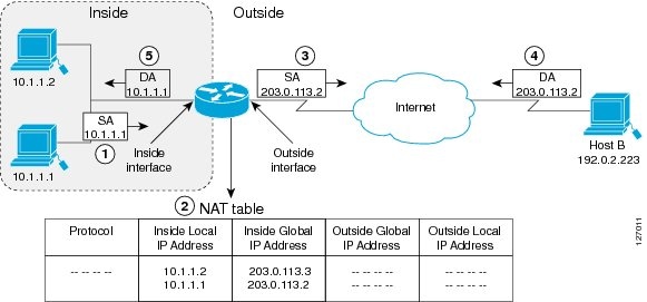
The following process describes inside source address translation, as shown in Figure 1:

1. The user at host 1.1.1.1 opens a connection to host B.

2. The first packet that the router receives from host 1.1.1.1 causes the router to check its NAT table:

If a static translation entry was configured, the router goes to Step 3.

If no translation entry exists, the router determines that source address (SA) 1.1.1.1 must be translated dynamically, selects a legal, global address from the dynamic address pool, and creates a translation entry. This type of entry is called a simple entry.

3. The router replaces the inside local source address of host 1.1.1.1 with the global address of the translation entry and forwards the packet.

4. Host B receives the packet and responds to host 1.1.1.1 by using the inside global IP destination—Address (DA) 2.2.2.2.

5. When the router receives the packet with the inside global IP address, it performs a NAT table lookup by using the inside global address as a key. It then translates the address to the inside local address of host 1.1.1.1 and forwards the packet to host 1.1.1.1.

Host 1.1.1.1 receives the packet and continues the conversation. The router performs Steps 2 through 5 for each packet.

Configuring Static Translation of Inside Source Addresses

Configure static translation of inside source addresses when you want to allow one-to-one mapping between your inside local address and an inside global address. Static translation is useful when a host on the inside must be accessible by a fixed address from the outside.

SUMMARY STEPS

1. enable

2. configure terminal

3. ip nat inside source static local-ip global-ip

4. interface type number

5. ip address ip-address mask secondary

6. ip nat inside

7. exit

8. interface type number

9. ip address ip-address mask

10. ip nat outside

DETAILED STEPS

 
Command or Action
Purpose

Step 1 

enable

Example:

Router> enable

Enables privileged EXEC mode.

Enter your password if prompted.

Step 2 

configure terminal

Example:

Router# configure terminal

Enters global configuration mode.

Step 3 

ip nat inside source static local-ip global-ip

Example:

Router(config)# ip nat inside source static 10.10.10.1 172.16.131.1

Establishes static translation between an inside local address and inside global address.

Step 4 

interface type number

Example:

Router(config)# interface ethernet 1

Specifies an interface and enters interface configuration mode.

Step 5 

ip address ip-address mask [secondary]

Example:

Router(config-if)# ip address 10.114.11.39 255.255.255.0

Sets a primary IP address for an interface.

Step 6 

ip nat inside

Example:

Router(config-if)# ip nat inside

Marks the interface as connected to the inside.

Step 7 

exit

Example:

Router(config-if)# exit

Exits interface configuration mode and returns to configuration mode.

Step 8 

interface type number

Example:

Router(config)# interface ethernet 0

Specifies a different interface and returns interface configuration mode.

Step 9 

ip address ip-address mask

Example:

Router(config-if)# ip address 172.31.232.182 255.255.255.240

Sets a primary IP address for an interface.

Step 10 

ip nat outside

Example:

Router(config-if)# ip nat outside

Marks the interface as connected to the outside.

Configuring Dynamic Translation of Inside Source Addresses

Dynamic translation establishes a mapping between an inside local address and a pool of global addresses. Dynamic translation is useful when multiple users on a private network need to access the Internet. The dynamically configured pool IP address may be used as needed and are released for use by other users when access to the Internet is no longer required.

SUMMARY STEPS

1. enable

2. configure terminal

3. ip nat pool name start-ip end-ip {netmask netmask | prefix-length prefix-length}

4. access-list access-list-number permit source [source-wildcard]

5. ip nat inside source list access-list-number pool name

6. interface type number

7. ip address ip-address mask

8. ip nat inside

9. exit

10. interface type number

11. ip address ip-address mask

12. ip nat outside

DETAILED STEPS

 
Command or Action
Purpose

Step 1 

enable

Example:

Router> enable

Enables privileged EXEC mode.

Enter your password if prompted.

Step 2 

configure terminal

Example:

Router# configure terminal

Enters global configuration mode.

Step 3 

ip nat pool name start-ip end-ip {netmask netmask | prefix-length prefix-length}

Example:

Router(config)# ip nat pool net-208 171.69.233.208 171.69.233.223 prefix-length 28

Defines a pool of global addresses to be allocated as needed.

Step 4 

access-list access-list-number permit source [source-wildcard]

Example:

Router(config)# access-list 1 permit 192.5.34.0 0.0.0.255

Defines a standard access list permitting those addresses that are to be translated.

Step 5 

ip nat inside source list access-list-number pool name

Example:

Router(config)# ip nat inside source list 1 pool net-208

Establishes dynamic source translation, specifying the access list defined in the prior step.

Step 6 

interface type number

Example:

Router(config)# interface ethernet 1

Specifies an interface and enters interface configuration mode.

Step 7 

ip address ip-address mask

Example:

Router(config-if)# ip address 10.114.11.39 255.255.255.0

Sets a primary IP address for the interface.

Step 8 

ip nat inside

Example:

Router(config-if)# ip nat inside

Marks the interface as connected to the inside.

Step 9 

exit

Example:

Router(config-if)# exit

Exits interface configuration mode and returns to configuration mode.

Step 10 

interface type number

Example:

Router(config-if)# interface ethernet 0

Specifies a different interface and returns to interface configuration mode.

Step 11 

ip address ip-address mask

Example:

Router(config)# ip address 172.69.232.182 255.255.255.240

Sets a primary IP address for the interface.

Step 12 

ip nat outside

Example:

Router(config-if)# ip nat outside

Marks the interface as connected to the outside.

Allowing Internal Users Access to the Internet Using NAT

Perform this task to allow your internal users access to the internet and conserve addresses in the inside global address pool using overloading of global addresses.

Inside Global Addresses Overloading

You can conserve addresses in the inside global address pool by allowing the router to use one global address for many local addresses. When this overloading is configured, the router maintains enough information from higher-level protocols (for example, TCP or UDP port numbers) to translate the global address back to the correct local address. When multiple local addresses map to one global address, the TCP or UDP port numbers of each inside host distinguish between the local addresses.

Figure 2 illustrates NAT operation when one inside global address represents multiple inside local addresses. The TCP port numbers act as differentiators.

Figure 2 NAT Overloading Inside Global Addresses

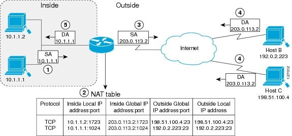
The router performs the following process in overloading inside global addresses, as shown in Figure 2. Both host B and host C believe they are communicating with a single host at address 2.2.2.2. They are actually communicating with different hosts; the port number is the differentiator. In fact, many inside hosts could share the inside global IP address by using many port numbers.

1. The user at host 1.1.1.1 opens a connection to host B.

2. The first packet that the router receives from host 1.1.1.1 causes the router to check its NAT table:

If no translation entry exists, the router determines that address 1.1.1.1 must be translated, and sets up a translation of inside local address 1.1.1.1 to a legal global address.

If overloading is enabled, and another translation is active, the router reuses the global address from that translation and saves enough information to be able to translate back. This type of entry is called an extended entry.

3. The router replaces the inside local source address 1.1.1.1 with the selected global address and forwards the packet.

4. Host B receives the packet and responds to host 1.1.1.1 by using the inside global IP address 2.2.2.2.

5. When the router receives the packet with the inside global IP address, it performs a NAT table lookup, using the protocol, the inside global address and port, and the outside address and port as a key; translates the address to inside local address 1.1.1.1; and forwards the packet to host 1.1.1.1.

Host 1.1.1.1 receives the packet and continues the conversation. The router performs Steps 2 through 5 for each packet.

SUMMARY STEPS

1. enable

2. configure terminal

3. ip nat pool name start-ip end-ip {netmask netmask| prefix-length prefix-length}

4. access-list access-list-number permit source [source-wildcard]

5. ip nat inside source list access-list-number pool name overload

6. interface type number

7. ip address ip-address mask

8. ip nat inside

9. exit

10. interface type number

11. ip address ip-address mask

12. ip nat outside

DETAILED STEPS

 
Command or Action
Purpose

Step 1 

enable

Example:

Router> enable

Enables privileged EXEC mode.

Enter your password if prompted.

Step 2 

configure terminal

Example:

Router# configure terminal

Enters global configuration mode.

Step 3 

ip nat pool name start-ip end-ip {netmask netmask | prefix-length prefix-length}

Example:

Router(config)# ip nat pool net-208 171.69.233.208 171.69.233.233 netmask 255.255.255.240

Defines a pool of global addresses to be allocated as needed.

Step 4 

access-list access-list-number permit source [source-wildcard]

Example:

Router(config)# access-list 1 permit 192.5.34.0 0.0.0.255

Defines a standard access list permitting those addresses that are to be translated.

The access list must permit only those addresses that are to be translated. (Remember that there is an implicit "deny all" at the end of each access list.) An access list that is too permissive can lead to unpredictable results.

Step 5 

ip nat inside source list access-list-number pool name overload

Example:

Router(config)# ip nat inside source list 1 pool net-208 overload

Establishes dynamic source translation with overloading, specifying the access list defined in the prior step.

Step 6 

interface type number

Example:

Router(config)# interface ethernet 1

Specifies an interface and enters interface configuration mode.

Step 7 

ip address ip-address mask

Example:

Router(config-if)# ip address 10.114.11.39 255.255.255.0

Sets a primary IP address for the interface.

Step 8 

ip nat inside

Example:

Router(config-if)# ip nat inside

Marks the interface as connected to the inside.

Step 9 

exit

Example:

Router(config-if)# exit

Exits interface configuration mode and returns to configuration mode.

Step 10 

interface type number

Example:

Router(config)# interface ethernet 0

Specifies a different interface and returns to interface configuration mode.

Step 11 

ip address ip-address mask

Example:

Router(config-if)# ip address 172.69.232.182 255.255.255.240

Sets a primary IP address for the interface.

Step 12 

ip nat outside

Example:

Router(config-if)# ip nat outside

Marks the interface as connected to the outside.

Configuring Address Translation Timeouts

The tasks in this section are presented together because they address similar objectives, but you must select the one that is applicable to the specific configuration of NAT.

Perform one of the following tasks:

Changing the Translation Timeout Default

Changing the Default Timeouts When Overloading Is Configured

Changing the Translation Timeout Default

By default, dynamic address translations time out after some period of non-use. You can change the default values on timeouts, if necessary. When overloading is not configured, simple translation entries time out after 24 hours.

SUMMARY STEPS

1. enable

2. configure terminal

3. ip nat translation timeout seconds

DETAILED STEPS

 
Command or Action
Purpose

Step 1 

enable

Example:

Router> enable

Enables privileged EXEC mode.

Enter your password if prompted.

Step 2 

configure terminal

Example:

Router# configure terminal

Enters global configuration mode.

Step 3 

ip nat translation timeout seconds

Example:

Router(config)# ip nat translation timeout 500

Changes the timeout value for dynamic address translations that do not use overloading.

Changing the Default Timeouts When Overloading Is Configured

If you have configured overloading, you have more control over translation entry timeout, because each entry contains more context about the traffic using it. To change timeouts on extended entries, use the following commands as needed.

SUMMARY STEPS

1. enable

2. configure terminal

3. ip nat translation udp-timeout seconds

4. ip nat translation dns-timeout seconds

5. ip nat translation tcp-timeout seconds

6. ip nat translation finrst-timeout seconds

7. ip nat translation icmp-timeout seconds

8. ip nat translation syn-timeout seconds

DETAILED STEPS

 
Command or Action
Purpose

Step 1 

enable

Example:

Router> enable

Enables privileged EXEC mode.

Enter your password if prompted.

Step 2 

configure terminal

Example:

Router# configure terminal

Enters global configuration mode.

Step 3 

ip nat translation udp-timeout seconds

Example:

Router(config)# ip nat translation udp-timeout 300

(Optional) Changes the UDP timeout value from 5 minutes.

Step 4 

ip nat translation dns-timeout seconds

Example:

Router(config)# ip nat translation dns-timeout 45

(Optional) Changes the DNS timeout value from 1 minute.

Step 5 

ip nat translation tcp-timeout seconds

Example:

Router(config)# ip nat translation tcp-timeout 2500

(Optional) Changes the TCP timeout value from 24 hours.

Step 6 

ip nat translation finrst-timeout seconds

Example:

Router(config)# ip nat translation finrst-timeout 45

(Optional) Changes the Finish and Reset timeout value from 1 minute.

Step 7 

ip nat translation icmp-timeout seconds

Example:

Router(config)# ip nat translation icmp-timeout 45

(Optional) Changes the ICMP timeout value from 24 hours.

Step 8 

ip nat translation syn-timeout seconds

Example:

Router(config)# ip nat translation syn-timeout 45

(Optional) Changes the Synchronous (SYN) timeout value from 1 minute.

Allowing Overlapping Networks to Communicate Using NAT

The tasks in this section are group together because they perform the same action but are executed differently depending on the type of translation that is implemented: static or dynamic.

Perform the task that applies to the translation type that is implemented.

Configuring Static Translation of Overlapping Networks

Configuring Dynamic Translation of Overlapping Networks

Address Translation of Overlapping Networks

NAT is used to translate your IP addresses, which could occur because your IP addresses are not legal, officially assigned IP addresses. Perhaps you chose IP addresses that officially belong to another network. The case of an address used both illegally and legally is called index overlapping. You can use NAT to translate inside addresses that overlap with outside addresses.

Figure 3 shows how NAT translates overlapping networks.

Figure 3 NAT Translating Overlapping Addresses

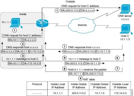
The router performs the following process when translating overlapping addresses:

1. The user at host 1.1.1.1 opens a connection to host C by name, requesting a name-to-address lookup from a DNS server.

2. The router intercepts the DNS reply and translates the returned address if there is an overlap (that is, the resulting legal address resides illegally in the inside network). To translate the return address, the router creates a simple translation entry mapping the overlapping address 1.1.1.3 to an address from a separately configured, outside local address pool.

The router examines every DNS reply from everywhere, ensuring that the IP address is not in the stub network. If it is, the router translates the address.

3. Host 1.1.1.1 opens a connection to 3.3.3.3.

4. The router sets up translations mapping inside local and global addresses to each other, and outside global and local addresses to each other.

5. The router replaces the SA with the inside global address and replaces the DA with the outside global address.

6. Host C receives the packet and continues the conversation.

7. The router does a lookup, replaces the DA with the inside local address, and replaces the SA with the outside local address.

8. Host 1.1.1.1 receives the packet and the conversation continues, using this translation process.

Configuring Static Translation of Overlapping Networks

Configure static translation of overlapping networks if your IP addresses in the stub network are legitimate IP addresses belonging to another network and you want to communicate with those hosts or routers using static translation.

SUMMARY STEPS

1. enable

2. configure terminal

3. ip nat inside source static local-ip global-ip

4. interface type number

5. ip address ip-address mask

6. ip nat inside

7. exit

8. interface type number

9. ip address ip-address mask

10. ip nat outside

DETAILED STEPS

 
Command or Action
Purpose

Step 1 

enable

Example:

Router> enable

Enables privileged EXEC mode.

Enter your password if prompted.

Step 2 

configure terminal

Example:

Router# configure terminal

Enters global configuration mode.

Step 3 

ip nat inside source static local-ip global-ip

Example:

Router(config)# ip nat inside source static 192.168.121.33 2.2.2.1

Establishes static translation between an inside local address and inside global address.

Step 4 

interface type number

Example:

Router(config)# interface ethernet 1

Specifies an interface and enters interface configuration mode.

Step 5 

ip address ip-address mask

Example:

Router(config-if)# ip address 10.114.11.39 255.255.255.0

Sets a primary IP address for the interface.

Step 6 

ip nat inside

Example:

Router(config-if)# ip nat inside

Marks the interface as connected to the inside.

Step 7 

exit

Example:

Router(config-if)# exit

Exits interface configuration mode and returns to configuration mode.

Step 8 

interface type number

Example:

Router(config)# interface ethernet 0

Specifies a different interface and returns to interface configuration mode.

Step 9 

ip address ip-address mask

Example:

Router(config-if)# ip address 172.69.232.182 255.255.255.240

Sets a primary IP address for the interface.

Step 10 

ip nat outside

Example:

Router(config-if)# ip nat outside

Marks the interface as connected to the outside.

What to Do Next

When you have completed all required configuration, go to the "Monitoring and Maintaining NAT" module.

Configuring Dynamic Translation of Overlapping Networks

Configure dynamic translation of overlapping networks if your IP addresses in the stub network are legitimate IP addresses belonging to another network and you want to communicate with those hosts or routers using dynamic translation.

SUMMARY STEPS

1. enable

2. configure terminal

3. ip nat pool name start-ip end-ip {netmask netmask | prefix-length prefix-length}

4. access-list access-list-number permit source [source-wildcard]

5. ip nat outside source list access-list-number pool name

6. interface type number

7. ip address ip-address mask

8. ip nat inside

9. exit

10. interface type number

11. ip address ip-address mask

12. ip nat outside

DETAILED STEPS

 
Command or Action
Purpose

Step 1 

enable

Example:

Router> enable

Enables privileged EXEC mode.

Enter your password if prompted.

Step 2 

configure terminal

Example:

Router# configure terminal

Enters global configuration mode.

Step 3 

ip nat pool name start-ip end-ip {netmask netmask | prefix-length prefix-length}

Example:

Router(config)# ip nat pool net-10 10.0.1.0 10.0.1.255 prefix-length 24

Defines a pool of global addresses to be allocated as needed.

Step 4 

access-list access-list-number permit source [source-wildcard]

Example:

Router(config)# access-list 1 permit 9.114.11.0 0.0.0.255

Defines a standard access list permitting those addresses that are to be translated.

The access list must permit only those addresses that are to be translated. (Remember that there is an implicit "deny all" at the end of each access list.) An access list that is too permissive can lead to unpredictable results.

Step 5 

ip nat outside source list access-list-number pool name

Example:

Router(config)# ip nat outside source list 1 pool net-10

Establishes dynamic outside source translation, specifying the access list defined in the prior step.

Step 6 

interface type number

Example:

Router(config)# interface ethernet 1

Specifies an interface and enters interface configuration mode.

Step 7 

ip address ip-address mask

Example:

Router(config-if)# ip address 10.114.11.39 255.255.255.0

Sets a primary IP address for the interface.

Step 8 

ip nat inside

Example:

Router(config-if)# ip nat inside

Marks the interface as connected to the inside.

Step 9 

exit

Example:

Router(config-if)# exit

Exits interface configuration mode and returns to configuration mode.

Step 10 

interface type number

Example:

Router(config)# interface ethernet 0

Specifies a different interface and returns to interface configuration mode.

Step 11 

ip address ip-address mask

Example:

Router(config-if)# ip address 172.69.232.182 255.255.255.240

Sets a primary IP address for the interface.

Step 12 

ip nat outside

Example:

Router(config-if)# ip nat outside

Marks the interface as connected to the outside.

Configuring the NAT Virtual Interface

The NAT Virtual Interface (NVI) feature removes the requirement to configure an interface as either Network Address Translation (NAT) inside or NAT outside. An interface can be configured to use NAT or not use NAT.

This section contains the following procedures:

Restrictions for NAT Virtual Interface

Enabling a Static NAT Virtual Interface

Before you configure the NAT Virtual Interface feature, you should understand the following concepts:

NAT Virtual Interface Design

Benefits of NAT Virtual Interface

NAT Virtual Interface Design

The NAT Virtual Interface feature allows all NAT traffic flows on the virtual interface, eliminating the need to specify inside and outside domains. When a domain is specified, the translation rules are applied either before or after route decisions depending on the traffic flow from inside to outside or outside to inside. The translation rules are applied only after the route decision for an NVI.

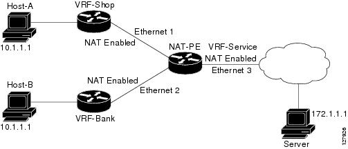
When a NAT pool is shared for translating packets from multiple networks connected to a NAT router, an NVI is created and a static route is configured that forwards all packets addressed to the NAT pool to the NVI. The standard interfaces connected to various networks will be configured to identify that the traffic originating and receiving on the interfaces needs to be translated.

Figure 4 shows a typical NAT virtual interface configuration.

Figure 4 NAT Virtual Interface Typical Configuration

Benefits of NAT Virtual Interface

A NAT table is maintained per interface for better performance and scalability.

Domain specific NAT configurations can be eliminated.

Restrictions for NAT Virtual Interface

Routemaps are not supported.

Enabling a Dynamic NAT Virtual Interface

Perform this task to enable a dynamic NAT virtual interface.

SUMMARY STEPS

1. enable

2. configure terminal

3. interface type number

4. ip nat enable

5. exit

6. ip nat pool name start-ip end-ip netmask netmask add-route

7. ip nat source list access-list-number pool name vrf name

8. ip nat source list access-list-number pool name vrf name overload

DETAILED STEPS

 
Command or Action
Purpose

Step 1 

enable

Example:

Router> enable

Enables privileged EXEC mode.

Enter your password if prompted.

Step 2 

configure terminal

Example:

Router# configure terminal

Enters global configuration mode.

Step 3 

interface type number

Example:

Router(config)# interface FastEthernet l

Configures an interface type and enters interface configuration mode.

Step 4 

ip nat enable

Example:

Router(config-if)# ip nat enable

Configures an interface connecting VPNs and the Internet for NAT.

Step 5 

exit

Example:

Router(config-if)# exit

Returns to global configuration mode.

Step 6 

ip nat pool name start-ip end-ip netmask netmask add-route

Example:

Router(config)# ip nat pool pool1 200.1.1.1 200.1.1.20 netmask 255.255.255.0 add-route

Configures a NAT pool and associated mappings.

Step 7 

ip nat source list access-list-number pool number vrf name

Example:

Router(config)# ip nat source list 1 pool 1 vrf shop

Configures a NAT virtual interface without inside or outside specification for the specified customer.

Step 8 

ip nat source list access-list-number pool number vrf name overload

Example:

Router(config)# ip nat source list 1 pool 1 vrf bank overload

Configures a NAT virtual interface without inside or outside specification for the specified customer.

Enabling a Static NAT Virtual Interface

Perform this task to enable a static NAT virtual interface.

SUMMARY STEPS

1. enable

2. configure terminal

3. interface type number

4. ip nat enable

5. exit

6. ip nat source static local-ip global-ip vrf name

DETAILED STEPS

 
Command or Action
Purpose

Step 1 

enable

Example:

Router> enable

Enables privileged EXEC mode.

Enter your password if prompted.

Step 2 

configure terminal

Example:

Router# configure terminal

Enters global configuration mode.

Step 3 

interface type number

Example:

Router(config)# interface FastEthernet l

Configures an interface type and enters interface configuration mode.

Step 4 

ip nat enable

Example:

Router(config-if)# ip nat enable

Configures an interface connecting VPNs and the Internet for NAT.

Step 5 

exit

Example:

Router(config-if)# exit

Returns to global configuration mode.

Step 6 

ip nat source static local-ip global-ip vrf name

Example:

Router(config)# ip nat source static 192.168.123.1 192.168.125.10 vrf bank

Configures a static NVI.

Avoiding Server Overload Using TCP Load Balancing

Perform this task to configure server TCP load balancing by way of destination address rotary translation. These commands allow you to map one virtual host to many real hosts. Each new TCP session opened with the virtual host will be translated into a session with a different real host.

TCP Load Distribution for NAT

Another use of NAT is unrelated to Internet addresses. Your organization may have multiple hosts that must communicate with a heavily used host. Using NAT, you can establish a virtual host on the inside network that coordinates load sharing among real hosts. DAs that match an access list are replaced with addresses from a rotary pool. Allocation is done on a round-robin basis, and only when a new connection is opened from the outside to the inside. Non-TCP traffic is passed untranslated (unless other translations are in effect). Figure 5 illustrates this feature.

Figure 5 NAT TCP Load Distribution

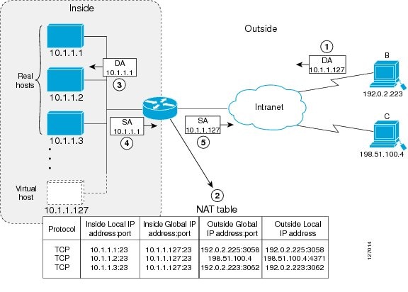
The router performs the following process when translating rotary addresses:

1. The user on host B (9.6.7.3) opens a connection to the virtual host at 1.1.1.127.

2. The router receives the connection request and creates a new translation, allocating the next real host (1.1.1.1) for the inside local IP address.

3. The router replaces the destination address with the selected real host address and forwards the packet.

4. Host 1.1.1.1 receives the packet and responds.

5. The router receives the packet, performs a NAT table lookup using the inside local address and port number, and the outside address and port number as the key. The router then translates the source address to the address of the virtual host and forwards the packet.

The next connection request will cause the router to allocate 1.1.1.2 for the inside local address.

SUMMARY STEPS

1. enable

2. configure terminal

3. ip nat pool name start-ip end-ip {netmask netmask | prefix-length prefix-length} type rotary

4. access-list access-list-number permit source [source-wildcard]

5. ip nat inside destination-list access-list-number pool name

6. interface type number

7. ip address ip-address mask

8. ip nat inside

9. exit

10. interface type number

11. ip address ip-address mask

12. ip nat outside

DETAILED STEPS

 
Command or Action
Purpose

Step 1 

enable

Example:

Router> enable

Enables privileged EXEC mode.

Enter your password if prompted.

Step 2 

configure terminal

Example:

Router# configure terminal

Enters global configuration mode.

Step 3 

ip nat pool name start-ip end-ip {netmask netmask | prefix-length prefix-length} type rotary

Example:

Router(config)# ip nat pool real-hosts 192.168.15.2 192.168.15.15 prefix-length 28 type rotary

Defines a pool of addresses containing the addresses of the real hosts.

Step 4 

access-list access-list-number permit source [source-wildcard]

Example:

Router(config)# access-list 1 permit 9.114.11.0 0.0.0.255

Defines an access list permitting the address of the virtual host.

Step 5 

ip nat inside destination-list access-list-number pool name

Example:

Router(config)# ip nat inside destination-list 2 pool real-hosts

Establishes dynamic inside destination translation, specifying the access list defined in the prior step.

Step 6 

interface type number

Example:
Router(config)# interface ethernet 0

Specifies an interface and enters interface configuration mode.

Step 7 

ip address ip-address mask

Example:

Router(config-if)# ip address 192.168.15.17 255.255.255.240

Sets a primary IP address for the interface.

Step 8 

ip nat inside

Example:

Router(config-if)# ip nat inside

Marks the interface as connected to the inside.

Step 9 

exit

Example:

Router(config-if)# exit

Exits interface configuration mode and returns to configuration mode.

Step 10 

interface type number

Example:

Router(config)# interface serial 0

Specifies a different interface and returns to interface configuration mode.

Step 11 

ip address ip-address mask

Example:

Router(config-if)# ip address 192.168.15.129 255.255.255.240

Sets a primary IP address for the interface.

Step 12 

ip nat outside

Example:

Router(config-if)# ip nat outside

Marks the interface as connected to the outside.

Using Route Maps for Address Translation Decisions

For NAT, a route map to be processed instead of an access list. A route map allows you to match any combination of access-list, next-hop IP address, and output interface to determine which pool to use. The ability to use route maps with static translations enables NAT multihoming capability with static address translations. Multihomed internal networks now can host common services such as the Internet and Domain Name System (DNS), which are accessed from different outside networks.

Benefits of Using Route Maps For Address Translation

The ability to configure route map statements provides the option of using IP Security (IPSec) with NAT.

Translation decisions can be made based on the destination IP address when static translation entries are used.

Prerequisites

All route maps required for use with this task should be configured prior to beginning the configuration task.

SUMMARY STEPS

1. enable

2. configure terminal

3. ip nat inside source {list {access-list-number | access-list-name} pool pool-name [overload] | static local-ip global-ip route-map map-name}

4. exit

5. show ip nat translations [verbose]

DETAILED STEPS

 
Command or Action
Purpose

Step 1 

enable

Example:

Router> enable

Enables privileged EXEC mode.

Enter your password if prompted.

Step 2 

configure terminal

Example:

Router# configure terminal

Enters global configuration mode.

Step 3 

ip nat inside source {list {access-list-number | access-list-name} pool pool-name [overload] | static local-ip global-ip route-map map-name}

Example:
Router(config)# ip nat inside source static 
11.1.1.2 192.68.1.21 route-map isp2 

Enables route mapping with static NAT configured on the NAT inside interface.

Step 4 

exit

Example:

Router(config)# exit

Exits global configuration mode and returns to privileged EXEC mode.

Step 5 

show ip nat translations [verbose]

Example:

Router# show ip nat translations

(Optional) Displays active NAT.

Enabling NAT Routemaps Outside-to-Inside Support

The NAT Routemaps Outside-to-Inside Support feature enables the deployment of a NAT routemap configuration that will allow IP sessions to be initiated from the outside to the inside. Perform this task to enable NAT Routemaps Outside-to-Inside Support.

Routemaps Outside-to-Inside Support Design

An initial session from inside-to-outside is required to trigger a NAT. New translation sessions can then be initiated from outside-to-inside to the inside host that triggered the initial translation.

When routemaps are used to allocate global addresses, the global address can allow return traffic, and the return traffic is allowed only if the return traffic matches the defined routemap in the reverse direction. Current functionality remains unchanged by not creating additional entries to allow the return traffic for a routemap-based dynamic entry unless the reversible keyword is used with the ip nat inside source command.

Restrictions

Only IP hosts that are part of the routemap configuration will allow outside sessions.

Outside-to-Inside support is not available with Port Address Translation (PAT).

Outside sessions must use an access list.

SUMMARY STEPS

1. enable

2. configure terminal

3. ip nat pool name start-ip end-ip netmask netmask

4. ip nat pool name start-ip end-ip netmask netmask

5. ip nat inside source rout-map name pool name [reversible]

6. ip nat inside source rout-map name pool name [reversible]

DETAILED STEPS

 
Command or Action
Purpose

Step 1 

enable

Example:

Router> enable

Enables privileged EXEC mode.

Enter your password if prompted.

Step 2 

configure terminal

Example:

Router# configure terminal

Enters global configuration mode.

Step 3 

ip nat pool name start-ip end-ip netmask netmask

Example:

Router# ip nat pool POOL-A 30.1.10.1 30.1.10.126 netmask 255.255.255.128

Defines a pool of network addresses for NAT.

Step 4 

ip nat pool name start-ip end-ip netmask netmask

Example:

Router# ip nat pool POOL-B 30.1.20.1 30.1.20.126 netmask 255.255.255.128

Defines a pool of network addresses for NAT.

Step 5 

ip nat inside source route-map name pool name reversible

Example:

Router# ip nat inside source route-map MAP-A pool POOL-A reversible

Enables outside-to-inside initiated sessions to use routemaps for destination-based NAT.

Step 6 

ip nat inside source route-map name pool name reversible

Example:

Router# ip nat inside source route-map MAP-B pool POOL-B reversible

Enables outside-to-inside initiated sessions to use routemaps for destination-based NAT.

Configuring NAT of External IP Addresses Only

When configuring NAT of external IP addresses only, NAT can be configured to ignore all embedded IP addresses for any application and traffic type. Traffic between a host and the outside world flows through the internal network. A router configured for NAT translates the packet to an address that is able to be routed inside the internal network. If the intended destination is the outside world, the packet gets translated back to an external address and sent out.

Benefits of Configuring NAT of External IP Addresses Only

Supports public and private network architecture with no specific route updates.

Gives the end client a usable IP address at the starting point. This address will be the address used for IP Security connections and traffic.

Allows the use of network architecture that requires only the header translation.

Allows an Enterprise to use the Internet as its enterprise backbone network.

SUMMARY STEPS

1. enable

2. configure terminal

3. ip nat inside source {list {access-list-number | access-list-name} pool pool-name [overload] | static network local-ip global-ip no-payload}

4. ip nat inside source {list {access-list-number | access-list-name} pool pool-name [overload] | static {tcp | upd} local-port global-port no-payload}

5. ip nat inside source {list {access-list-number | access-list-name} pool pool-name [overload] | static [network] local-network-mask global-network-mask no-payload}

6. ip nat outside source {list {access-list-number | access-list-name} pool pool-name [overload] | static local-ip global-ip no-payload}

7. ip nat outside source {list {access-list-number | access-list-name} pool pool-name [overload] | static {tcp | upd} local-port global-port no-payload}

8. ip nat outside source {list {access-list-number | access-list-name} pool pool-name [overload] | static [network] local-network-mask global-network-mask no-payload}

9. exit

10. show ip nat translations [verbose]

DETAILED STEPS

 
Command or Action
Purpose

Step 1 

enable

Example:

Router> enable

Enables privileged EXEC mode.

Enter your password if prompted.

Step 2 

configure terminal

Example:

Router# configure terminal

Enters global configuration mode.

Step 3 

ip nat inside source {list {access-list-number | access-list-name} pool pool-name [overload] | static [network] local-ip global-ip no-payload}

Example:
Router(config)# ip nat inside source static 
network 4.1.1.0 192.168.251.0/24 no-payload 

Disables the network packet translation on the inside host router.

Step 4 

ip nat inside source {list {access-list-number | access-list-name} pool pool-name [overload] | static {tcp | upd} local-port global-port no-payload}

Example:
Router(config)# ip nat inside source static tcp 
10.1.1.1 2000 192.1.1.1 2000 no-payload

Disables port packet translation on the inside host router.

Step 5 

ip nat inside source {list {access-list-number | access-list-name} pool pool-name [overload] |static [network] local-network-mask global-network-mask no-payload}

Example:
Router(config)# p nat inside source static 
10.1.1.1 192.1.1.1 no-payload

Disables the packet translation on the inside host router.

Step 6 

ip nat outside source {list {access-list-number | access-list-name} pool pool-name [overload] | static local-ip global-ip no-payload}

Example:

Router(config)# ip nat outside source static 10.1.1.1 192.1.1.1 no-payload

Disables packet translation on the outside host router.

Step 7 

ip nat outside source {list {access-list-number | access-list-name} pool pool-name [overload] | static {tcp | upd} local-port global-port no-payload}

Example:

Router(config)# ip nat outside source static tcp 10.1.1.1 20000 192.1.1.1 20000 no-payload

Disables port packet translation on the outside host router.

Step 8 

ip nat outside source {list {access-list-number | access-list-name} pool pool-name [overload] | static [network] local-network-mask global-network-mask no-payload}

Example:

Router(config)# ip nat outside source static network 4.1.1.0 192.168.251.0/24 no-payload

Disables network packet translation on the outside host router.

Step 9 

exit

Example:

Router(config)# exit

Exits global configuration mode and returns to privileged EXEC mode.

Step 10 

show ip nat translations [verbose]

Example:

Router# show ip nat translations

Displays active NAT.

Configuring NAT for a Default Inside Server

The NAT Default Inside Server feature provides for the need to forward packets from the outside to a specified inside local address. Traffic is redirected that does not match any existing dynamic translations or static port translations, and the packets are not dropped. For online games, outside traffic comes on different User Datagram Ports (UDP).

Dynamic mapping and interface overload can be configured for the PC traffic and also for the gaming device. If a packet is destined for the 806 interface from the outside and there is not a match in the NAT table for the fully extended entry or a match for the static port entry, it will be forwarded to the gaming device using a simple static entry created as a result of the new command line interface (CLI).

Restrictions

This feature is used for configuring gaming devices with a different IP address than the PC. To avoid unwanted traffic or attacks, access lists should be used.

For traffic going from the PC to the outside world, it is better that a route map be used so that extended entries are created.

SUMMARY STEPS

1. enable

2. configure terminal

3. ip nat inside source static local-ip interface type number

4. ip nat inside source static tcp local-ip local-port interface global-port

5. exit

6. show ip nat translations [verbose]

DETAILED STEPS

 
Command or Action
Purpose

Step 1 

enable

Example:

Router> enable

Enables privileged EXEC mode.

Enter your password if prompted.

Step 2 

configure terminal

Example:

Router# configure terminal

Enters global configuration mode.

Step 3 

ip nat inside source static local-ip interface type number

Example:

Router(config)# ip nat inside source static 1.1.1.1 interface Ethernet1/1

Enables static NAT on the interface.

Step 4 

ip nat inside source static tcp local-ip local-port interface global-port

Example:

Router(config)# ip nat inside source static tcp 1.1.1.1 23 interface 23

(Optional) Enables the use of telnet to the router from the outside.

Step 5 

exit

Example:

Router(config)# exit

Exits global configuration mode and returns to privileged EXEC mode.

Step 6 

show ip nat translations [verbose]

Example:

Router# show ip nat translations

(Optional) Displays active NAT.

Configuring NAT RTSP Support Using NBAR

The Real Time Streaming Protocol (RTSP) is a client-server multimedia presentation control protocol that supports multimedia application delivery. Some of the applications that use RTSP include Windows Media Services (WMS) by Microsoft, QuickTime by Apple Computer, and RealSystem G2 by RealNetworks.

When the RTSP protocol passes through a NAT router, the embedded address and port must be translated in order for the connection to be successful. NAT uses Network Based Application Recognition (NBAR) architecture to parse the payload and translate the embedded information in the RTSP payload.

RTSP is enabled by default. Use the following commands to re-enable RTSP on a NAT router if this configuration has been disabled.

SUMMARY STEPS

enable

configure terminal

ip nat service rtsp port port-number

end

DETAILED STEPS

 
Command or Action
Purpose

Step 1 

enable

Example:

Router> enable

Enables privileged EXEC mode.

Enter your password if prompted.

Step 2 

configure terminal

Example:

Router# configure terminal

Enters global configuration mode.

Step 3 

ip nat service rtsp port port-number

Example:

Router(config)# ip nat service rtsp port 554

Enables RTSP packets by NAT.

Step 4 

end

Example:

Router(config)# end

Saves the configuration and exits global configuration mode.

Configuring Support for Users with Static IP Addresses

Configuring support for users with static IP addresses enables those users to establish an IP session in a Public Wireless LAN environment.

The NAT Static IP Support feature extends the capabilities of Public Wireless LAN providers to support users configured with a static IP address. By configuring a router to support users with a static IP address, Public Wireless LAN providers extend their services to a greater number of potential users, which can lead to greater user satisfaction and additional revenue.

Users with static IP addresses can use services of the public wireless LAN provider without changing their IP address. NAT entries are created for static IP clients and a routable address is provided.

This section contains the following procedures:

Configuring Static IP Support, page 37

Verifying Static IP Support

Public Wireless LAN

A Public Wireless LAN provides users of mobile computing devices with wireless connections to a public network, such as the Internet.

RADIUS

Remote Authentication Dial-In User Service (RADIUS) is a distributed client/server system that secures networks against unauthorized access. Communication between a network access server (NAS) and a RADIUS server is based on the User Datagram Protocol (UDP). Generally, the RADIUS protocol is considered a connectionless service. Issues related to server availability, retransmission, and timeouts are handled by the RADIUS-enabled devices rather than the transmission protocol.

RADIUS is a client/server protocol. The RADIUS client is typically a NAS, and the RADIUS server is usually a daemon process running on a UNIX or Windows NT machine. The client passes user information to designated RADIUS servers and acts on the response that is returned. RADIUS servers receive user connection requests, authenticate the user, and then return the configuration information necessary for the client to deliver service to the user. A RADIUS server can act as a proxy client to other RADIUS servers or other kinds of authentication servers.

Prerequisites

Before configuring support for users with static IP addresses for NAT, you must first enable NAT on your router and configure a RADIUS server host. For additional information on NAT and RADIUS configuration, see the "Related Documents" section.

Configuring Static IP Support

Perform this task to configure the NAT Static IP Support feature.

SUMMARY STEPS

1. enable

2. configure terminal

3. interface type number

4. ip nat inside

5. exit

6. ip nat allow-static-host

7. ip nat pool name start-ip end-ip netmask netmask accounting list-name

8. ip nat inside source list access-list-number pool name

9. access-list access-list-number deny ip source

DETAILED STEPS

 
Command or Action
Purpose

Step 1 

enable

Example:

Router> enable

Enables privileged EXEC mode.

Enter your password if prompted.

Step 2 

configure terminal

Example:

Router# configure terminal

Enters global configuration mode.

Step 3 

interface type number

Example:

Router(config)# interface ethernet 1

Specifies the interface to be configured, and enters interface configuration mode.

Step 4 

ip nat inside

Example:

Router(config-if)# ip nat inside

Marks the interface as connected to the inside.

Step 5 

exit

Example:

Router(config-if)# exit

Exits interface configuration mode and returns to global configuration mode.

Step 6 

ip nat allow-static-host

Example:

Router(config)# ip nat allow-static-host

Enables static IP address support.

Dynamic Address Resolution Protocol (ARP) learning will be disabled on this interface, and NAT will control the creation and deletion of ARP entries for the static-IP host.

Step 7 

ip nat pool name start-ip end-ip netmask netmask accounting list-name

Example:

Router(config)# ip nat pool xyz 171.1.1.1 171.1.1.10 netmask 255.255.255.0 accounting WLAN-ACCT

Specifies an existing RADUIS profile name to be used for authentication of the static IP host.

Step 8 

ip nat inside source list access-list-number pool name

Example:

Router(config)# ip nat inside source list 1 pool net-208

Specifies the access list and pool to be used for static IP support.

The specified access list must permit all traffic.

Step 9 

access-list access-list-number deny ip source

Example:

Router(config)# access-list 1 deny ip 192.168.196.51

Removes the router's own traffic from NAT.

The source argument is the IP address of the router that supports the NAT Static IP Support feature.

Verifying Static IP Support

To verify the NAT Static IP Support feature, use the following command.

SUMMARY STEPS

1. show ip nat translations verbose

DETAILED STEPS


Step 1 show ip nat translations verbose

Use this command to verify that NAT is configured to support static IP addresses, for example:

Router# show ip nat translations verbose

--- 171.1.1.11         10.1.1.1           ---                ---
create 00:05:59, use 00:03:39, left 23:56:20, Map-Id(In): 1, flags: none wlan-flags: 
Secure ARP added, Accounting Start sent Mac-Address:0010.7bc2.9ff6 Input-IDB:Ethernet1/2, 
use_count: 0, entry-id:7, lc_entries: 0

Configuring Support for ARP Ping in a Public Wireless LAN

When the static IP client's NAT entry times out, the NAT entry and the secure ARP entry associations are deleted for the client. Reauthentication with the Service Selection Gateway (SSG) is needed for the client to reestablish WLAN services. The ARP Ping feature enables the NAT entry and the secure ARP entry to not be deleted when the static IP client exists in the network where the IP address is unchanged after authentication.

An ARP ping is necessary to determine static IP client existence and to restart the NAT entry timer.

SUMMARY STEPS

1. enable

2. configure terminal

3. ip nat pool name start-ip end-ip prefix-length prefix-length [accounting] method-list-name [arp-ping]

DETAILED STEPS

 
Command or Action
Purpose

Step 1 

enable

Example:

Router> enable

Enables privileged EXEC mode.

Enter your password if prompted.

Step 2 

configure terminal

Example:

Router# configure terminal

Enters global configuration mode.

Step 3 

ip nat pool name start-ip end-ip prefix-length [accounting] method-list-name [arp-ping]

Example:

Router(config)# ip nat pool net-208 171.69.233.208 171.69.233.223 prefix-length 28 accounting radius1 arp-ping

Defines a pool of IP addresses for NAT.

Step 4 

ip nat translation arp-ping-timeout [timeout-value]

Example:

Router(config)# ip nat translation arp-ping-timeout 600

Changes the amount of time after each network address translation.

Limiting the Number of Concurrent NAT Operations

Limiting the number of concurrent NAT operations using the Rate Limiting NAT Translation feature provides users more control over how NAT addresses are used. The Rate Limiting NAT Translation feature can be used to limit the effects of viruses, worms, and denial-of-service attacks.

Benefits of Limiting the Number of concurrent NAT Operations

Since NAT is a CPU-intensive process, router performance can be adversely affected by denial-of-service attacks, viruses, and worms that target NAT. The Rate Limiting NAT Translation feature allows you to limit the maximum number of concurrent NAT requests on a router.

Denial-of-Service Attacks

A denial-of-service (DoS) attack typically involves the misuse of standard protocols or connection processes with the intent to overload and disable a target, such as a router or web server. DoS attacks can come from a malicious user or from a computer infected with a virus or worm. When the attack comes from many different sources at once, such as when a virus or worm has infected many computers, it is known as a distributed denial-of-service (DDoS) attack. Such DDoS attacks can spread rapidly and involve thousands of systems.

Viruses and Worms That Target NAT

Viruses and worms are malicious programs designed to attack computer and networking equipment. While viruses are typically embedded in discrete applications and only run when executed, worms self-propagate and can quickly spread on their own. Although a specific virus or worm may not expressly target NAT, it might use NAT resources to propagate itself. The Rate Limiting NAT Translation feature can be used to limit the impact of viruses and worms that originate from specific hosts, access control lists, and VPN routing and forwarding (VRF) instances.

Prerequisites

Classify current NAT usage and determine the sources of requests for NAT. If a specific host, access control list, or VRF instance is generating an unexpectedly high number of NAT requests, it may be the source of a malicious virus or worm attack.

Once you have identified the source of excess NAT requests, you can set a NAT rate limit that contains a specific host, access control list, or VRF instance, or you can set a general limit for the maximum number of NAT requests allowed regardless of their source.

SUMMARY STEPS

1. enable

2. show ip nat translations

3. configure terminal

4. ip nat translation max-entries {number | all-vrf number | host ip-address number | list listname number | vrf name number}

5. end

6. show ip nat statistics

DETAILED STEPS

 
Command or Action
Purpose

Step 1 

enable

Example:

Router enable

Enables privileged EXEC mode.

Enter your password if prompted.

Step 2 

show ip nat translations

Example:

Router# show ip nat translations

(Optional) Displays active NAT.

If a specific host, access control list, or VRF instance is generating an unexpectedly high number of NAT requests, it may be the source of a malicious virus or worm attack.

Step 3 

configure terminal

Example:

Router# configure terminal

Enters global configuration mode.

Step 4 

ip nat translation max-entries {number | all-vrf number | host ip-address number | list listname number | vrf name number}

Example:

Router(config)# ip nat translation max-entries 300

Configures the maximum number of NAT entries allowed from the specified source.

The maximum number of allowed NAT entries is 2147483647, although a typical range for a NAT rate limit is 100 to 300 entries.

When configuring a NAT rate limit for all VRF instances, each VRF instance is limited to the maximum number of NAT entries that you specify.

When configuring a NAT rate limit for a specific VRF instance, you can specify a maximum number of NAT entries for the named VRF instance that is greater than or less than that allowed for all VRF instances.

Step 5 

end

Example:

Router(config)# end

Exits global configuration mode and returns to privileged EXEC mode.

Step 6 

show ip nat statistics

Example:

Router# show ip nat statistics

(Optional) Displays current NAT usage information, including NAT rate limit settings.

After setting a NAT rate limit, use the show ip nat statistics command to verify current NAT rate limit settings.

Configuration Examples for Configuring NAT for IP Address Conservation

This section provides the following configuration examples:

Configuring Static Translation of Inside Source Addresses: Examples

Configuring Dynamic Translation of Inside Source Addresses: Example

Overloading Inside Global Addresses: Example

Translating Overlapping Address: Example

Enabling NAT Virtual Interface: Example

Avoiding Server Overload Using Load Balancing: Example

Enabling NAT Route Mapping: Example

Enabling NAT Routemaps Outside-to-Inside Support: Example

Configuring NAT Translation of External IP Addresses Only: Example

Configuration Examples for NAT Static IP Support

Configuration Examples for Rate Limiting NAT Translation

Configuring Static Translation of Inside Source Addresses: Examples

The following example translates between inside hosts addressed from the 9.114.11.0 network to the globally unique 171.69.233.208/28 network. Further packets from outside hosts addressed from the 9.114.11.0 network (the true 9.114.11.0 network) are translated to appear to be from the 10.0.1.0/24 network.

ip nat pool net-208 171.69.233.208 171.69.233.223 prefix-length 28
ip nat pool net-10 10.0.1.0 10.0.1.255 prefix-length 24
ip nat inside source list 1 pool net-208
ip nat outside source list 1 pool net-10
!
interface ethernet 0
 ip address 171.69.232.182 255.255.255.240
 ip nat outside
!
interface ethernet 1
 ip address 9.114.11.39 255.255.255.0
 ip nat inside
!
access-list 1 permit 9.114.11.0 0.0.0.255

The following example shows NAT configured on the Provider Edge (PE) router with a static route to the shared service for the gold and silver Virtual Private Networks (VPNs). NAT is configured as inside source static one-to-one translations.

ip nat pool outside 4.4.4.1 4.4.4.254 netmask 255.255.255.0
ip nat outside source list 1 pool mypool
access-list 1 permit 168.58.18.0 0.0.0.255
ip nat inside source static 192.168.121.33 2.2.2.1 vrf gold
ip nat inside source static 192.169.121.33.2.2.2.2 vrf silver

Configuring Dynamic Translation of Inside Source Addresses: Example

The following example translates between inside hosts addressed from either the 192.168.1.0 or 192.168.2.0 network to the globally unique 171.69.233.208/28 network:

ip nat pool net-208 171.69.233.208 171.69.233.223 prefix-length 28
ip nat inside source list 1 pool net-208
!
interface ethernet 0
 ip address 171.69.232.182 255.255.255.240
 ip nat outside
!
interface ethernet 1
 ip address 192.168.1.94 255.255.255.0
 ip nat inside
!
access-list 1 permit 192.168.1.0 0.0.0.255
access-list 1 permit 192.168.2.0 0.0.0.255


The following example translates only traffic local to the provider edge device running NAT (NAT-PE):

ip nat inside source list 1 interface e 0 vrf shop overload
ip nat inside source list 1 interface e 0 vrf bank overload
!
ip route vrf shop 0.0.0.0 0.0.0.0 192.1.1.1
ip route vrf bank 0.0.0.0 0.0.0.0 192.1.1.1
!
access-list 1 permit 10.1.1.1.0 0.0.0.255
!
ip nat inside source list 1 interface e 1 vrf shop overload
ip nat inside source list 1 interface e 1 vrf bank overload
!
ip route vrf shop 0.0.0.0 0.0.0.0 172.1.1.1 global
ip route vrf bank 0.0.0.0 0.0.0.0 172.1.1.1 global
access-list 1 permit 10.1.1.0 0.0.0.255

Overloading Inside Global Addresses: Example

The following example creates a pool of addresses named net-208. The pool contains addresses from 171.69.233.208 to 171.69.233.233. Access list 1 allows packets having the SA from 192.168.1.0 to 192.168.1.255. If no translation exists, packets matching access list 1 are translated to an address from the pool. The router allows multiple local addresses (192.168.1.0 to 192.168.1.255) to use the same global address. The router retains port numbers to differentiate the connections.

ip nat pool net-208 171.69.233.208 171.69.233.233 netmask 255.255.255.240
ip nat inside source list 1 pool net-208 overload
!
interface serial0
 ip address 171.69.232.182 255.255.255.240
 ip nat outside
!
interface ethernet0
 ip address 192.168.1.94 255.255.255.0
 ip nat inside
!
access-list 1 permit 192.168.1.0 0.0.0.255

Translating Overlapping Address: Example

In the following example, the addresses in the local network are being used legitimately by someone else on the Internet. An extra translation is required to access that external network. Pool net-10 is a pool of outside local IP addresses. The ip nat outside source list 1 pool net-10 statement translates the addresses of hosts from the outside overlapping network to addresses in that pool.

ip nat pool net-208 171.69.233.208 171.69.233.223 prefix-length 28
ip nat pool net-10 10.0.1.0 10.0.1.255 prefix-length 24
ip nat inside source list 1 pool net-208
ip nat outside source list 1 pool net-10
!
interface serial 0
 ip address 171.69.232.192 255.255.255.240
 ip nat outside
!
interface ethernet0
 ip address 192.168.1.94 255.255.255.0
 ip nat inside
!
access-list 1 permit 192.168.1.0 0.0.0.255

Enabling NAT Virtual Interface: Example

The following example shows how to configure NAT virtual interfaces without the use of inside or outside source addresses:

interface Ethernet0/0
 ip vrf forwarding bank
 ip address 192.168.122.1 255.255.255.0
 ip nat enable
!
interface Ethernet1/0
 ip vrf forwarding park
 ip address 192.168.122.1 255.255.255.0
 ip nat enable
!
interface Serial2/0
 ip vrf forwarding services
 ip address 192.168.123.2 255.255.255.0
ip nat enable
!
ip nat pool NAT 192.168.25.20 192.168.25.30 netmask 255.255.255.0 add-route
ip nat source list 1 pool NAT vrf bank overload
ip nat source list 1 pool NAT vrf park overload
ip nat source static 192.168.123.1 192.168.125.10 vrf services
! 
access-list 1 permit 192.168.122.20
access-list 1 permit 192.168.122.0 0.0.0.255
!

Avoiding Server Overload Using Load Balancing: Example

In the following example, the goal is to define a virtual address, connections to which are distributed among a set of real hosts. The pool defines the addresses of the real hosts. The access list defines the virtual address. If a translation does not already exist, TCP packets from serial interface 0 (the outside interface) whose destination matches the access list are translated to an address from the pool.

ip nat pool real-hosts 192.168.15.2 192.168.15.15 prefix-length 28 type rotary
ip nat inside destination list 2 pool real-hosts
!
interface serial 0
 ip address 192.168.15.129 255.255.255.240
 ip nat outside
!
interface ethernet 0
 ip address 192.168.15.17 255.255.255.240
 ip nat inside
!
access-list 2 permit 192.168.15.1

Enabling NAT Route Mapping: Example

The following example shows the use of route mapping with static NATs:

interface Ethernet3 
ip address 172.68.1.100 255.255.255.0 
ip nat outside 
media-type 10BaseT 
! 
interface Ethernet4 
ip address 192.68.1.100 255.255.255.0 
ip nat outside 
media-type 10BaseT 
! 
interface Ethernet5 
ip address 11.1.1.100 255.255.255.0 
ip nat inside 
media-type 10BaseT 
! 
router rip 
network 172.68.0.0 
network 192.68.1.0 
! 
ip nat inside source static 11.1.1.2 192.68.1.21 route-map isp2 
ip nat inside source static 11.1.1.2 172.68.1.21 route-map isp1 
ip nat inside source static 11.1.1.1 192.68.1.11 route-map isp2 
ip nat inside source static 11.1.1.1 172.68.1.11 route-map isp1 
!
access-list 101 permit ip 11.1.1.0 0.0.0.255 172.0.0.0 0.255.255.255. 
access-list 102 permit ip 11.1.1.0 0.0.0.255 192.0.0.0 0.255.255.255 
! 
route-map isp2 permit 10 
match ip address 102 
set ip next-hop 192.68.1.1 
! 
route-map isp1 permit 10 
match ip address 101 
set ip next-hop 172.68.1.1 

Enabling NAT Routemaps Outside-to-Inside Support: Example

The following example shows how to configure routemap A and routemap B to allow outside-to-inside translation for a destination-based NAT.

ip nat pool POOL-A 30.1.10.1 30.1.10.126 netmask 255.255.255.128
ip nat pool POOL-B 30.1.20.1 30.1.20.126 netmask 255.255.255.128
ip nat inside source route-map MAP-A pool POOL-A reversible
ip nat inside source route-map MAP-B pool POOL-B reversible
!
ip access-list extended ACL-A
 permit ip any 30.1.10.128 0.0.0.127
ip access-list extended ACL-B
 permit ip any 30.1.20.128 0.0.0.127
!
route-map MAP-A permit 10
 match ip address ACL-A
!
route-map MAP-B permit 10
 match ip address ACL-B

Configuring NAT Translation of External IP Addresses Only: Example

The following example shows how to translate the packet to an address that is able to be routed inside the internal network:

interface ethernet 3 
ip address 20.1.1.1 255.255.255.0 
ip nat outside 
no ip mroute-cache 
media-type 10BaseT 
! 
interface Ethernet4 
ip address 192.168.15.1 255.255.255.0 
ip nat inside 
no ip mroute-cache 
media-type 10BaseT 
! 
router rip 
network 20.0.0.0 
Network 192.168.15.0 
! 
ip nat outside source static network 4.1.1.0 192.168.251.0/24 no-payload 
!
ip route 2.1.1.0 255.255.255.0 Ethernet4 
ip route 4.1.1.0 255.255.255.0 Ethernet3 

Configuration Examples for NAT Static IP Support

This section provides the following configuration examples:

Configuring NAT Static IP Support: Example

Creating a RADIUS Profile for NAT Static IP Support: Example

Configuring NAT Static IP Support: Example

The following example shows how to enable static IP address support for the router at 192.168.196.51:

interface ethernet 1
 ip nat inside
ip nat allow-static-host
ip nat pool xyz 171.1.1.1 171.1.1.10 netmask 255.255.255.0 accounting WLAN-ACCT
ip nat inside source list 1 pool net-208
access-list 1 deny ip 192.168.196.51

Creating a RADIUS Profile for NAT Static IP Support: Example

The following example shows how to create a RADIUS profile for use with the NAT Static IP Support feature:

aaa new-model

!

aaa group server radius WLAN-RADIUS

server 168.58.88.1 auth-port 1645 acct-port 1645

server 168.58.88.1 auth-port 1645 acct-port 1646

!

aaa accounting network WLAN-ACCT start-stop group WLAN-RADIUS

aaa session-id common

ip radius source-interface Ethernet3/0

radius-server host 168.58.88.1 auth-port 1645 acct-port 1646

radius-server key cisco

Configuration Examples for Rate Limiting NAT Translation

This section provides the following configuration examples:

Setting a Global NAT Rate Limit: Example

Setting NAT Rate Limits for a Specific VRF Instance: Example

Setting NAT Rate Limits for All VRF Instances: Example

Setting NAT Rate Limits for Access Control Lists: Example

Setting NAT Rate Limits for an IP Address: Example

Setting a Global NAT Rate Limit: Example

The following example shows how to limit the maximum number of allowed NAT entries to 300:

ip nat translation max-entries 300

Setting NAT Rate Limits for a Specific VRF Instance: Example

The following example shows how to limit the VRF instance named "vrf1" to 150 NAT entries:

ip nat translation max-entries vrf vrf1 150

Setting NAT Rate Limits for All VRF Instances: Example

The following example shows how to limit each VRF instance to 200 NAT entries:

ip nat translation max-entries all-vrf 200

The following example shows how to limit the VRF instance named "vrf2" to 225 NAT entries, but limit all other VRF instances to 100 NAT entries each:

ip nat translation max-entries all-vrf 100
ip nat translation max-entries vrf vrf2 225

Setting NAT Rate Limits for Access Control Lists: Example

The following example shows how to limit the access control list named "vrf3" to 100 NAT entries:

ip nat translation max-entries list vrf3 100

Setting NAT Rate Limits for an IP Address: Example

The following example shows how to limit the host at IP address 127.0.0.1 to 300 NAT entries:

ip nat translation max-entries host 127.0.0.1 300

Where to Go Next

To configure NAT for use with application level gateways, see the "Using Application Level Gateways with NAT" module.

To verify, monitor, and maintain NAT, see the "Monitoring and Maintaining NAT" module.

To integrate NAT with MPLS VPNs, see the "Integrating NAT with MPLS VPNs" module

To configure NAT for high availability, see the "Configuring NAT for High Availability" module.

Additional References

The following sections provide references related to Configuring NAT for IP Address Conservation.

Related Documents

Related Topic
Document Title

Using NAT with MPLS VPNs

"Integrating NAT with MPLS VPNs"

Using HSRP and SNAT for high availability

"Configuring NAT for High Availability"

NAT maintenance

"Monitoring and Maintaining NAT"

NAT commands: complete command syntax, command mode command history, defaults, usage guidelines, and examples

"IP Addressing Commands" chapter in the Cisco IOS IP Command Reference, Volume 1 of 3: Addressing and Services, Release 12.4T

Public Wireless LAN access routers

PWLAN Access Routers, for Cisco IOS Release 12.3(4)T

RADIUS

Cisco IOS Security Command Reference, Release 12.3(4)T

SSG

Service Selection Gateway, Release 12.3(4)T


Standards

Standards
Title

None


MIBs

MIBs
MIBs Link

None

To locate and download MIBs for selected platforms, Cisco IOS releases, and feature sets, use Cisco MIB Locator found at the following URL:

http://www.cisco.com/go/mibs


RFCs

RFCs
Title

RFC 1597

Internet Assigned Numbers Authority

RFC 1631

The IP Network Address Translation (NAT)

RFC 1918

Address Allocation for Private Internets

RFC 2663

IP Network Address Translation (NAT) Terminology and Considerations

RFC 3022

Traditional IP Network Address Translation (Traditional NAT)


Technical Assistance

Description
Link

The Cisco Technical Support & Documentation website contains thousands of pages of searchable technical content, including links to products, technologies, solutions, technical tips, and tools. Registered Cisco.com users can log in from this page to access even more content.

http://www.cisco.com/techsupport


Feature Information for Configuring NAT for IP Address Conservation

Table 1 lists the features in this module and provides links to specific configuration information. Only features that were introduced or modified in Cisco IOS Release 12.2(4)T, 12.2(4)2T, 12.3(13)T or later appear in the table.

Not all commands may be available in your Cisco IOS software release. For details on when support for specific commands was introduced, see the command reference documents.

If you are looking for information on a feature in this technology that is not documented here, see the "Configuring Network Address Translation Features Roadmap."

Cisco IOS software images are specific to a Cisco IOS software release, a feature set, and a platform. Use Cisco Feature Navigator to find information about platform support and Cisco IOS software image support. Access Cisco Feature Navigator at http://www.cisco.com/go/fn. You must have an account on Cisco.com. If you do not have an account or have forgotten your username or password, click Cancel at the login dialog box and follow the instructions that appear.


Note Table 1 lists only the Cisco IOS software release that introduced support for a given feature in a given Cisco IOS software release train. Unless noted otherwise, subsequent releases of that Cisco IOS software release train also support that feature.


Table 1 Feature Information for Configuring NAT for IP Address Conservation

Feature Name
Releases
Feature Configuration Information

NAT Ability to Use Route Maps with Static Translation

12.2.(4)T

This feature provides a dynamic translation command that can specify a route map to be processed instead of an access-list. A route map allows you to match any combination of access-list, next-hop IP address, and output interface to determine which pool to use. The ability to use route maps with static translations enables NAT multihoming capability with static address translations.

The following section provides information about this feature:

"Using Route Maps for Address Translation Decisions" section

NAT Default Inside Server

12.3(13)T

The NAT Default Inside Server feature provides for the need to forward packets from the outside to a specified inside local address.

The following section provides information about this feature:

"Configuring NAT for a Default Inside Server" section

NAT Routemaps Outside-to-Inside Support

12.3(14)T

The NAT Routemaps Outside-to-Inside Support feature enables the deployment of a NAT routemap configuration that will allow IP sessions to be initiated from the outside to the inside.

The following sections provide information about this feature:

"Enabling NAT Routemaps Outside-to-Inside Support" section

"Enabling NAT Routemaps Outside-to-Inside Support: Example" section

NAT RTSP Support Using NBAR

12.3(7)T

The Real Time Streaming Protocol (RTSP) is a client-server multimedia presentation control protocol that supports multimedia application delivery. Some of the applications that use RTSP include Windows Media Services (WMS) by Microsoft, QuickTime by Apple Computer, and RealSystem G2 by RealNetworks.

The following section provides information about this feature:

"Configuring NAT RTSP Support Using NBAR" section

NAT Static IP Support

12.3(7)T

The NAT Static IP Support feature provides support for users with static IP addresses, enabling those users to establish an IP session in a Public Wireless LAN environment.

The following sections provide information about this feature:

"Configuring Support for Users with Static IP Addresses" section

"Configuration Examples for NAT Static IP Support" section

NAT Translation of External IP addresses only

12.2(4)T

12.2(4)T2

Using the NAT of external IP address only feature, NAT can be configured to ignore all embedded IP addresses for any application and traffic type.

The following sections provide information about this feature:

"Configuring NAT of External IP Addresses Only" section

"Configuring NAT of External IP Addresses Only" section

NAT Virtual Interface (NVI)

12.3(14)T

The NAT Virtual Interface (NVI) feature removes the requirement to configure an interface as either Network Address Translation (NAT) inside or NAT outside. An interface can be configured to use NAT or not use NAT.

The following sections provide information about this feature:

Configuring the NAT Virtual Interface

"Enabling NAT Virtual Interface: Example" section

Rate Limiting NAT Translation feature

12.3(4)T

The Rate Limiting NAT Translation feature provides the ability to limit the maximum number of concurrent Network Address Translation (NAT) operations on a router. In addition to giving users more control over how NAT addresses are used, the Rate Limiting NAT Translation feature can be used to limit the effects of viruses, worms, and denial-of-service attacks.

The following sections provide information about this feature:

"Limiting the Number of Concurrent NAT Operations" section

"Configuration Examples for Rate Limiting NAT Translation" section

Configuring Support for ARP Ping in a Public Wireless LAN

12.4(6)T

The ARP Ping feature enables the NAT entry and the secure ARP entry to not be deleted when the static IP client exists in the network where the IP address is unchanged after authentication.

The following section provides information about this feature:

"Configuring Support for ARP Ping in a Public Wireless LAN" section