Cisco Virtual Network Management Center Quick Start Guide, Release 2.0
Available Languages
Table Of Contents
Cisco Virtual Network Management Center 2.0 Quick Start Guide
Cisco Virtual Network Management Center Documentation
Cisco Virtual Security Gateway Documentation
Cisco Nexus 1000V Series Switch Documentation
Obtaining Documentation and Submitting a Service Request
Configuring Chrome for Use with VNMC
Task 2—Configuring VNMC Connectivity with vCenter
Downloading the vCenter Extension File
Registering the vCenter Extension Plug-In in vCenter
Configuring vCenter in VNMC VM Manager
Task 3—Registering an ASA 1000V to VNMC
Task 4—Verifying VSG, VSM, and ASA 1000V Registration in VNMC
Task 6—Configuring a Service Profile in VNMC
Task 7—Configuring a Device Profile in VNMC
Task 8—Configuring a Compute Firewall
Task 9—Assigning a Compute Firewall to a VSG
Task 10—Creating an Edge Security Profile
Task 11—Configuring Access Rules
Task 12—Configuring an Edge Firewall
Task 13—Associating an Edge Firewall with an ASA 1000V Instance
Enabling Policy-Engine Logging in a Monitor Session
Enabling Global Policy-Engine Logging
Troubleshooting VNMC Installation and Configuration
Examining Faults and Configuration Errors for Edge Firewalls
Examining Faults and Configuration Errors for Compute Firewalls
Backing Up VNMC 1.x Data Using the CLI
Upgrading to VNMC 2.0 Using the CLI
Backing Up VNMC 2.0 Using the GUI
Restoring the Previous VNMC Version
Exporting and Importing in VNMC
Exporting VNMC Configuration Data
Importing VNMC Configuration Data
Quick Start Guide
Cisco Virtual Network Management Center 2.0 Quick Start Guide
Revised: July 9, 2013, OL-27555-01
1 Preface
This guide explains how to install Cisco Virtual Network Management Center (VNMC) 2.0.
Related Documentation
The following topics contain information about the documentation available for VNMC and related products:
•
Cisco Virtual Network Management Center Documentation
•
•
•
Cisco Virtual Network Management Center Documentation
The following Cisco Virtual Network Management Center documents are available at the following URL:
http://www.cisco.com/en/US/products/ps11213/tsd_products_support_series_home.html
•
•
•
•
•
•
•
Cisco Virtual Security Gateway Documentation
The Cisco Virtual Security Gateway (VSG) for Nexus 1000V Series switch documentation is available at the following URL:
http://www.cisco.com/en/US/products/ps11208/tsd_products_support_model_home.html
Cisco Nexus 1000V Series Switch Documentation
The Cisco Nexus 1000V Series switch documentation is available at the following URL:
http://www.cisco.com/en/US/products/ps9902/tsd_products_support_series_home.html
Cisco ASA 1000V Documentation
The Cisco Adaptive Security Appliance (ASA) documentation is available at the following URL:
http://www.cisco.com/en/US/products/ps12233/tsd_products_support_series_home.html
Obtaining Documentation and Submitting a Service Request
For information on obtaining documentation, submitting a service request, and gathering additional information, see the monthly What's New in Cisco Product Documentation, which also lists all new and revised Cisco technical documentation, at:
http://www.cisco.com/en/US/docs/general/whatsnew/whatsnew.html
Subscribe to the What's New in Cisco Product Documentation as an RSS feed and set content to be delivered directly to your desktop using a reader application. The RSS feeds are a free service. Cisco currently supports RSS Version 2.0.
2 Installation Prerequisites
The following tables list the requirements for installing and configuring VNMC, and for configuring communications with VSG, ASA 1000V, and Cisco Virtual Supervisor Module (VSM):
•
•
•
•
•

Note
Table 2 Web-Based GUI Client Requirements
Operating system
Either of the following:
•
•
Browser
Any of the following:
•
•
•
Flash Player
Adobe Flash Player plugin (version 11.2)
1 We recommend Mozilla Firefox 11.0 with Adobe Flash Player 11.2.
2 Before you can use Chrome with VNMC 2.0, you must first disable the Adobe Flash Players that are installed by default with Chrome. For more information, see Configuring Chrome for Use with VNMC.
Table 5 Information Required for Installation and Configuration
Name
Location of files
Data store location
Storage location, if more than one location is available
Management port profile name for VM management
Note
IP address
Subnet mask
Gateway IP address
Domain name
DNS server
Admin password
Shared secret password for communications between VNMC, VSG, ASA 1000V, and VSM. (See Shared Secret Password Criteria.)
vCenter name
Description
Hostname or IP address
Shared Secret Password Criteria
A shared secret password is a password that is known only to those using a secure communication channel. Passwords are designated as strong if they cannot be easily guessed for unauthorized access. When you set a shared secret password for communications between VNMC, VSG, ASA 1000V, and VSM, adhere to the following criteria for setting valid, strong passwords:
•
–
–
•
Examples of strong passwords are:
•
•
•
Configuring Chrome for Use with VNMC
To use Chrome with VNMC 2.0, you must disable the Adobe Flash Players that are installed by default with Chrome.
Note
To disable default Adobe Flash Players in Chrome:
Step 1
Step 2
Step 3
Step 4
Step 5
3 Installing VNMC
Note
This procedure describes how to deploy the VNMC OVA, resulting in a VNMC VM.
Before You Begin
•
•
•
•
•
To deploy the VNMC OVA:
Step 1
Step 2
Step 3
Step 4
Step 5
Step 6
Step 7
Step 8
Step 9
The storage can be local or shared remote, such as NFS or SAN.
Note
Step 10
The default is thick provisioned. If you do not want to allocate the storage immediately, use thin provisioned.
Note
Step 11
Step 12
Note
Step 13

Caution
A progress indicator shows the task progress until VNMC is deployed.
Step 14
Example Screens Showing OVA Deployment
Figure 1 Source Screen

Figure 2 Datastore Screen
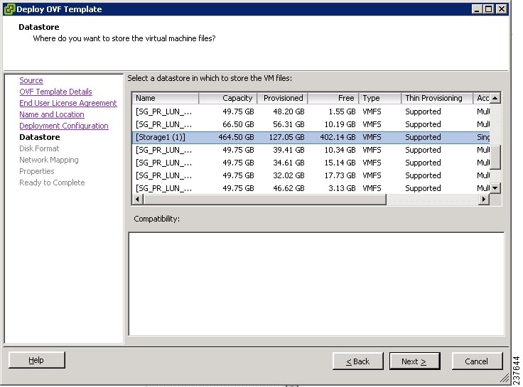
Figure 3 Properties Screen

Figure 4 Ready to Complete Screen

4 Configuring VNMC
Table 7 provides a checklist of the VNMC configuration tasks.
Table 7 Task Checklist for VNMC 2.0 Configuration
Task 4—Verifying VSG, VSM, and ASA 1000V Registration in VNMC
Task 13—Associating an Edge Firewall with an ASA 1000V Instance
Task 1—Configuring NTP
Before you perform any operations in VNMC, configure Network Time Protocol (NTP) on ASA 1000V, VSG, and VSM. If you do not do so, ASA 1000Vs, VSGs, and VSMs will not be able to register with VNMC.
To configure NTP in VNMC, ASA 1000V, VSG, and VSM:
3.
Configuring NTP in VSM
To configure NTP, enter the following CLI command from the VSM console:
ntp server x.x.x.xwhere x.x.x.x is the NTP server IP address.
Configuring NTP in VSG
To configure NTP, enter the following CLI command from the VSG console:
ntp server x.x.x.xwhere x.x.x.x is the NTP server IP address.
Note
Configuring NTP in ASA 1000V
Before you install ASA 1000V in VNMC, be sure to configure NTP on all ESX and ESXi servers that run ASA 1000V. For information, see Configuring Network Time Protocol (NTP) on ESX/ESXi 4.1 and ESXi 5.0 hosts using the vSphere Client.
After installation, ASA 1000V receives the Real Time Clock (RTC) value from the VMware ESX or ESXi host.
Configuring NTP in VNMC
To configure NTP in VNMC:
Step 1
Step 2
Step 3
Step 4
a.
b.
c.
Step 5
a.
b.
c.
d.
Caution
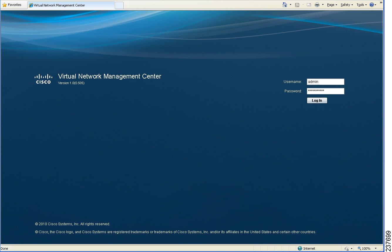
Example Screen Showing the VNMC Login Window
Figure 5 VNMC Login Window
Task 2—Configuring VNMC Connectivity with vCenter
After you deploy the VNMC OVA, you need to establish connectivity with VMware vCenter by:
1.
2.
3.
Before You Begin
Make sure you have the information identified in Table 5.
Downloading the vCenter Extension File
The first step in setting up vCenter connectivity is to download the vCenter extension file.
To download the vCenter extension file:
Step 1
Step 2
Step 3
Example Screen Showing VM Managers Pane
Figure 6 VM Managers Pane

Registering the vCenter Extension Plug-In in vCenter
To register the vCenter extension plug-in in vCenter:
Step 1
Step 2
Step 3

Tip
Step 4
The vCenter Register Plug-in Window (see Figure 8) appears, displaying a security warning.
Step 5
A progress indicator shows the task status.
Step 6
Example Screens Showing vCenter Extension Plug-In Registration
Figure 7 vSphere Client Directory

Figure 8 vCenter Register Plug-in Window

Configuring vCenter in VNMC VM Manager
To configure vCenter in VNMC VM Manager:
Step 1
Step 2
Step 3
A successfully added VM manager is displayed with the following information:
•
•
•
Task 3—Registering an ASA 1000V to VNMC
Before You Begin
•
•
•
To register an ASA 1000V to VNMC from within vSphere Client:
Step 1
Step 2
Step 3
Step 4
ciscoasa> enablePassword:ciscoasa# configure terminalciscoasa(config)# vnmc policy-agentciscoasa(config-vnmc-policy-agent)# registration host n.n.n.nciscoasa(config-vnmc-policy-agent)# shared-secret MySharedSecret
Task 4—Verifying VSG, VSM, and ASA 1000V Registration in VNMC
Before You Begin
•
•
If you are installing VSM:
a.
b.
c.
d.
If you are registering VSG with VNMC:
a.
b.
c.
d.
If you are registering ASA 1000V with VNMC:
a.
b.
c.
d.
Note
To verify if VSG, VSM, and ASA 1000V are registered with VNMC:
Step 1
Step 2
Example Screen Showing the Client Window
Figure 9 Clients Window

Task 5—Configuring a Tenant
Tenants are entities (such as businesses, agencies, or institutions) whose data and processes are hosted on VMs in a virtual data center. To provide firewall security for each tenant, you must first configure the tenant in VNMC.
To configure a tenant:
Step 1
Step 2
Step 3
The newly created tenant is listed in the navigation pane under root (see Figure 11).
Example Screens Showing Tenant Configuration
Figure 10 Tenant Management Root Pane

Figure 11 VNMC Navigation Pane with Tenant

Task 6—Configuring a Service Profile in VNMC
A profile is a collection of policies. By creating a profile and then applying that profile to one or more objects (such as a data interface for an ASA 1000V or a VSM port profile), you can ensure that those objects have consistent policies.
To configure a compute security profile in VNMC:
Step 1
Step 2
Step 3
Task 7—Configuring a Device Profile in VNMC
To configure a device profile in VNMC:
Step 1
Step 2
Step 3
Task 8—Configuring a Compute Firewall
A compute firewall is a logical virtual entity in VNMC that contains the device profile that you assign to a VSG VM. Any device policies that are in the VNMC device profile are applied to the assigned VSG. After the policy has been applied to the VSG, the compute firewall is in an applied configuration state in VNMC.
To configure a compute firewall:
Step 1
Step 2
Step 3
The VNMC window is refreshed and displays the newly created compute firewall.
Field Descriptions
Example Screen Showing the Add Compute Firewall Dialog Box
Figure 12 Add Compute Firewall Dialog Box

Task 9—Assigning a Compute Firewall to a VSG
After you configure a compute firewall in VNMC, you can assign it to a VSG so that the device policies in the specified device profile are applied to the VSG.
To assign a compute firewall to a VSG:
Step 1
Step 2
Step 3
As the configuration is applied to the VSG, the Config State status changes from not-applied to applying, and then to applied.
Task 10—Creating an Edge Security Profile
VNMC provides support for virtual edge firewalls, such as an ASA 1000V instance. After you add a virtual edge firewall, you can:
•
•
•
•
To create an edge security profile:
Step 1
Step 2
Step 3
a.
b.
c.
Note
Step 4
a.
b.
c.
Note
Step 5
Field Descriptions
Table 9 Add NAT Policy Set Dialog Box Fields
Name
NAT policy set name.
Description
Brief NAT policy set description.
Admin State
Enable or disable the Admin state.
Policies
1.
2.
3.
Table 10 Add NAT Policy Dialog Box Fields
Name
NAT policy name.
Description
Brief NAT policy description.
Admin State
Enable or disable the Admin state.
Rule Table
1.
2.
3.
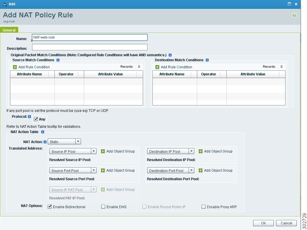
Table 11 Add NAT Policy Rule Dialog Box Fields
Name
NAT policy name.
Description
Brief NAT policy description.
Source Match Conditions
To add a add rule condition to the following:
1.
2.
3.
Destination Match Conditions
To add a add rule condition to the following:
1.
2.
3.
Protocol
Protocols to be examined for this policy rule:
•
•
NAT Action
Choose either a static or a dynamic NAT action.
Source IP Pool
Source Port Pool
Destination IP Pool
Destination Port Pool
Choose the required IP pool or port pool from the drop-down list. To add an object group, do the following:
1.
2.
3.
NAT Options
Choose the required NAT options.
Table 13 Add Object Group Fields
Name
Object group name.
Description
Brief object group description.
Expression
1.
2.
3.
Example Screen Showing the Add NAT Policy Rule Dialog Box
Figure 13 Add NAT Policy Rule Dialog Box
Task 11—Configuring Access Rules
Access rules in VNMC permit or deny traffic based on the following items:
•
•
•
•
To configure access rules:
Step 1
Step 2
Step 3
Step 4
Step 5
a.
b.
c.
Note
Step 6
The VNMC window is refreshed, and the ACL Policy Sets table contains the new policy set.
Field Descriptions
Example Screens Showing Access Rule Configuration
Figure 14 Add ACL Policy Set Dialog Box
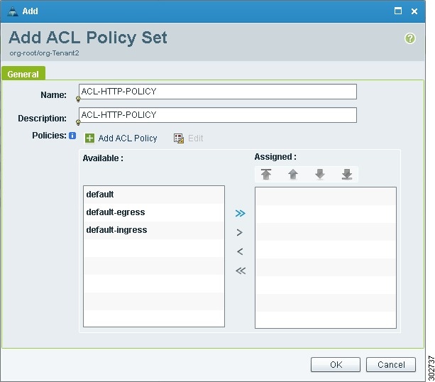
Figure 15 Add ACL Policy Rule Dialog Box

Task 12—Configuring an Edge Firewall
To configure an edge firewall:
Step 1
Step 2
Step 3
Step 4
a.
b.
c.
d.
Step 5
Field Descriptions
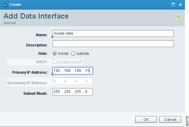
Example Screen Showing Edge Firewall Configuration
Figure 16 Add Edge Firewall Dialog Box

Figure 17 Add Data Interface Dialog Box
Task 13—Associating an Edge Firewall with an ASA 1000V Instance
To associate an edge firewall with an ASA 1000V instance:
Step 1
The VNMC GUI displays the newly added edge firewall (see Figure 18) and the following information:
•
•
•
•
Step 2
Step 3
Step 4
The VNMC GUI now displays the edge firewall (see Figure 18) and the following additional information:
•
•
•
–
–
–
–
–
Step 5
Example Screen Showing the Newly Added Edge Firewall
Figure 18 Newly Added Edge Firewall with ASA 1000V Information

Task 14—Enabling Logging
If appropriate for your environment, you can configure and enable syslog policies for VSG or ASA 1000V elements by:
•
•
Configuring and enabling a syslog policy for a VSG or ASA 1000V element ensures that you receive syslog messages for the severities that you specify. For example, depending on the syslog policy, you could receive syslog messages notifying you that a firewall rule has been invoked and that a permit or deny action has been taken.
Logging enables you to monitor traffic, troubleshoot issues, and verify that devices are configured and operating properly.
Enabling Policy-Engine Logging in a Monitor Session
To enable logging level 6 for policy-engine logging in a monitor session:
Step 1
Step 2
Step 3
Step 4
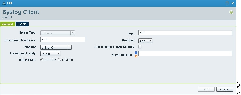
Step 5
•
•
•
The Syslog Policy dialog box is refreshed with the updated information.
Step 6
Example Screens Showing Enabling Policy-Engine Logging
Figure 19 Syslog Policy Dialog Box
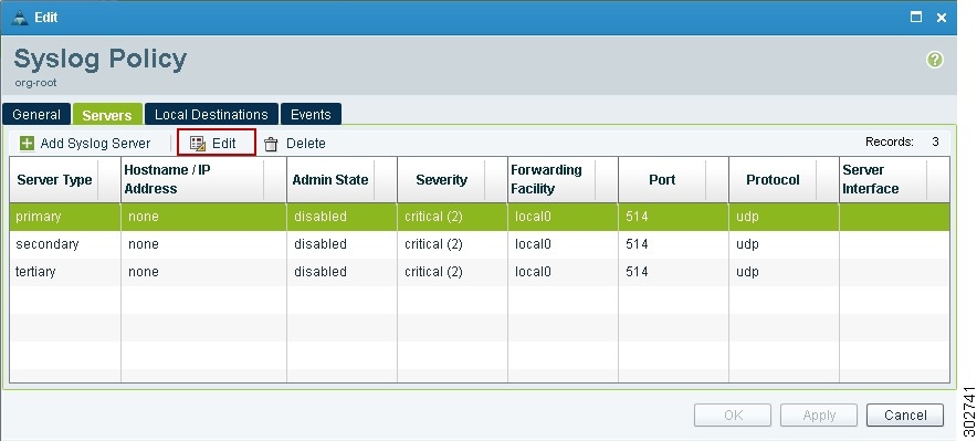
Figure 20 Syslog Client Dialog Box
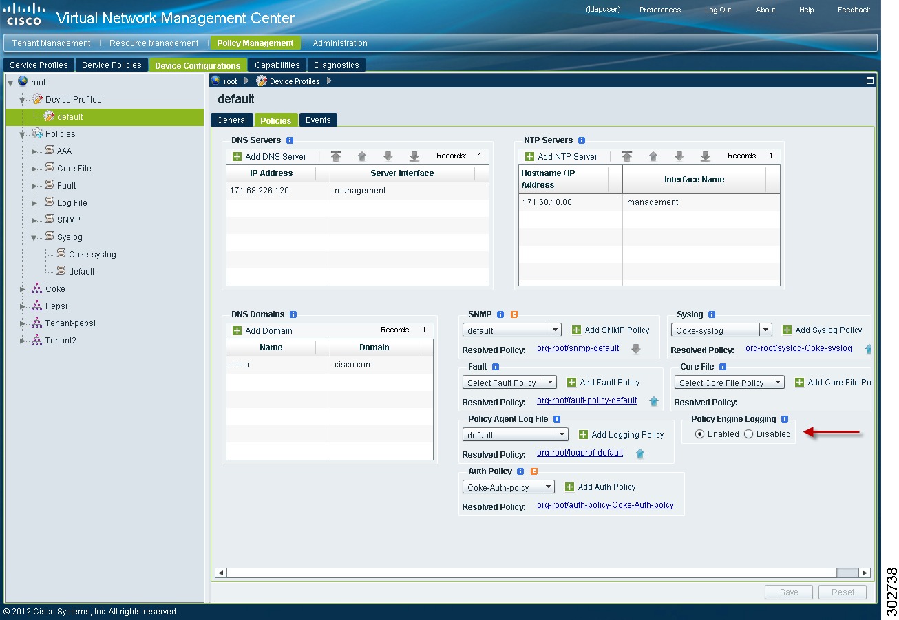
Enabling Global Policy-Engine Logging
To enable global policy-engine logging:
Step 1
Step 2
Step 3
Example Screens Showing Global Policy-Engine Logging
Figure 21 Device Profiles Pane
5 Troubleshooting VNMC Installation and Configuration
The VNMC interface provides links to browser windows that enable you to examine policy and configuration errors that prevent the successful application of a policy, or to review the faults and events associated with successfully applied policies and configurations. This same feature enables you to examine the faults associated with a compute firewall or an edge firewall.
Examining Faults and Configuration Errors for Edge Firewalls
Before You Begin
Associate the edge firewall to an ASA 1000V instance.
To examine faults and configuration errors for edge firewalls:
Step 1
Step 2
Step 3
•
•
•
Step 4
Tip
Step 5
Example of the Fault Table Window Screen
Figure 22 Fault or Event Details
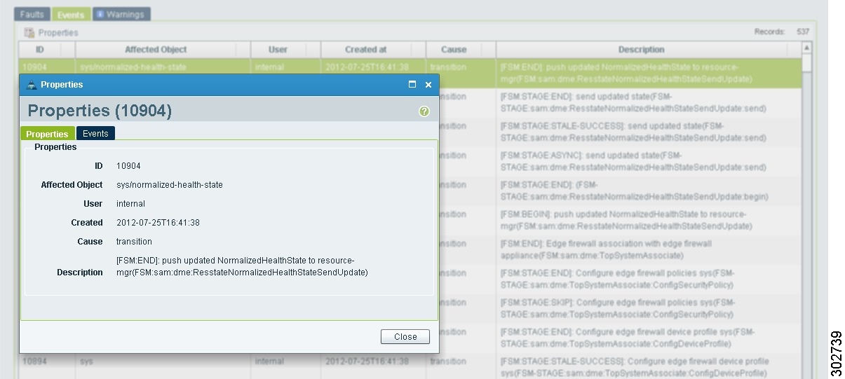
Examining Faults and Configuration Errors for Compute Firewalls
Before You Begin
Associate the compute firewall with a VSG instance.
To examine faults for compute firewalls:
Step 1
Step 2
The Fault Table is displayed in a new browser window, and includes the fault severity, affected object, cause, last transition, acknowledgement state, type, and description.
Step 3
6 Upgrading VNMC
Note
To upgrade from VNMC 1.x to VNMC 2.0, complete the following procedures:
1.
2.
Note
1. Clear the browser cache and browsing history.
2. Close all browser instances.
3. Relaunch the browser.
This note applies to all supported browsers: Internet Explorer, Mozilla Firefox, and Chrome.
Backing Up VNMC 1.x Data Using the CLI
To save a state for recovery purposes, back up your existing VNMC data via SCP.
You can use one of the following methods to back up VNMC data:
•
•
The following procedure uses these settings:
•
•
•
•
•
•
Note
Before You Begin
Temporarily disable the Cisco Security Agent (CSA) on the remote file server.
Note
To back up VNMC using the CLI:
Step 1
ssh admin@10.1.1.10Step 2
scope systemStep 3
create backup scp://user@host/file full-state enabledwhere:
•
•
•
Step 4
Step 5
Step 6
Example Backup
vnmc# scope systemvnmc /system # create backup scp://backupuser@10.2.3.4/tmp/my-backup.etgz full-state enabledPassword:vnmc /system/backup* # commit-buffervnmc /system/backup #Upgrading to VNMC 2.0 Using the CLI
After you back up the VNMC 1.x data, you are ready to upgrade to VNMC 2.0.
Caution
Note
To upgrade VNMC 2.0 using the CLI:
Step 1
ssh admin@10.1.1.10Step 2
connect local-mgmtStep 3
show versionStep 4
copy scp://<imageURLtoBinFile> bootflash:/where the VNMC 2.0 image filename is vnmc.2.0.0.XXXX.bin.
Step 5
update bootflash:/vnmc.2.0.0.XXXX.binStep 6
service restartStep 7
service statusFor the CLI output of this command, see Upgrade CLI Output.
Step 8
show versionFor the CLI output of this command, see Upgrade CLI Output.
Step 9
If your browser displays the previous version of VNMC instead of the upgraded version:
a.
b.
c.
Examples Showing VNMC Upgrade CLI Outputs
The output of Step 7 (VNMC service status) should look similar to this:SERVICE NAME STATE RETRY(MAX) CORE------------ ----- ---------- ----pmon running N/A N/Acore-svc_cor_dme running 0(4) noservice-reg-svc_reg_dme running 0(4) nocore-svc_cor_secAG running 0(4) noresource-mgr-svc_res_dme running 0(4) nopolicy-mgr-svc_pol_dme running 0(4) nosam_cores_mon.sh running 0(4) novm-mgr-svc_vmm_dme running 0(4) nocore-svc_cor_controllerAG running 0(4) novm-mgr-svc_vmm_vmAG running 0(4) nocore-httpd.sh running 0(4) nocore-svc_cor_sessionmgrAG running 0(4) noThe output of Step 8 (after the upgrade) should look similar to this:
Name Package Version GUI---- ------- ------- ----core Base System 2.0 2.0service-reg Service Registry 2.0 2.0policy-mgr Policy Manager 2.0 2.0resource-mgr Resource Manager 2.0 2.0vm-mgr VM manager 2.0 noneTo restore to the previous VNMC version, see Restoring the Previous VNMC Version.
7 Backing Up and Restoring VNMC
Note
VNMC enables you to back up and restore data for the same VNMC version. That is, the following backup and restore operations are supported:
•
•
Backing up one version and restoring to another version (such as backing up VNMC 1.x and restoring to VNMC 2.0) is not supported.
Note
The following topics describe how to back up data and restore data from VNMC 2.0:
•
•
Backing Up VNMC 2.0 Using the GUI
To save a state for recovery purposes, perform a backup via the GUI or CLI, using one of the following methods:
•
•
Before You Begin
Temporarily disable the CSA on the remote file server.
Note
To back up VNMC 2.0 using the GUI:
Step 1
Step 2
Step 3
•
•
•
•
•
•
Step 4
Step 5
Restoring the Previous VNMC Version
If the upgrade fails, use the CLI to restore the previous version.
Before You Begin
Temporarily disable the CSA on the remote file server.
Note
Note
To restore to the previous VNMC version:
Step 1
ssh admin@10.1.1.10Step 2
connect local-mgmtStep 3
show versionStep 4
copy scp://imageURLtoBinFile bootflash:/where the VNMC 1.x image filename is vnmc.1.x.0.XXXX.bin.
Step 5
update bootflash:/vnmc.1.XXXX.bin forceStep 6
restore scp://backupuser@10.2.3.4/tmp/my-backup.etgzStep 7
service restartStep 8
service statusFor the CLI output of this command, see Restore CLI Output.
Step 9
show versionFor the CLI output of this command, see Restore CLI Output.
Step 10
If your browser displays the previous version of VNMC instead of the upgraded version, clear the browser cache and browsing history.
Example Showing VNMC Restore CLI Outputs
The output of Step 8 (VNMC service status) should look similar to this:
SERVICE NAME STATE RETRY(MAX) CORE------------ ----- ---------- ----pmon running N/A N/Acore-svc_cor_dme running 0(4) noservice-reg-svc_reg_dme running 0(4) nocore-svc_cor_secAG running 0(4) noresource-mgr-svc_res_dme running 0(4) nopolicy-mgr-svc_pol_dme running 0(4) nosam_cores_mon.sh running 0(4) novm-mgr-svc_vmm_dme running 0(4) nocore-svc_cor_controllerAG running 0(4) novm-mgr-svc_vmm_vmAG running 0(4) nocore-httpd.sh running 0(4) nocore-svc_cor_sessionmgrAG running 0(4) noThe output of Step 9 (after the restore) should look similar to this:
Name Package Version GUI----- -------- ------- ---core Base System 1.3 1.3service-reg Service Registry 1.3 1.3policy-mgr Policy Manager 1.3 1.3resource-mgr Resource Manager 1.3 1.3vm-mgr VM manager 1.3 none8 Exporting and Importing in VNMC
Note
VNMC enables you to export and import data for the same VNMC version. That is, the following export and import operations are supported:
•
•
Exporting from one version and importing into another version (such as exporting from VNMC 1.x and importing into VNMC 2.0) is not supported.
Note
Exporting VNMC Configuration Data
Before You Begin
Temporarily disable the CSA on the remote SCP server.
Note
To export configuration data from one VNMC server to another:
Step 1
Step 2
•
•
•
•
•
•
•
Step 3
Step 4
Step 5
Importing VNMC Configuration Data
Before You Begin
Temporarily disable the CSA on the remote SCP server.
Note
To perform the import of the previously exported data:
Step 1
Step 2
•
•
•
•
•
•
Step 3
Step 4
The configuration in /tmp/my-XML.tgz will be applied to the VNMC server on which the import operation is performed.
Caution
9 Patching VNMC
Use the CLI to apply the patch.
Before You Begin
Temporarily disable the CSA on the remote SCP server.
Note
Note
To patch VNMC 2.0:
Step 1
ssh admin@10.1.1.10Step 2
connect local-mgmtStep 3
update bootflash: | ftp: | scp: | sftp:For example:
update bootflash:/vnmc.2.0.0.511.binStep 4
service restartStep 5
service statusFor the CLI output of this command, see After Patch CLI Output.
Step 6
show update-history
Example of VNMC Service Status After Patch
The output for Step 5 (VNMC service status) should look similar to the following example:
SERVICE NAME STATE RETRY(MAX) CORE------------ ----- ---------- ----pmon running N/A N/Acore-svc_cor_dme running 0(4) noservice-reg-svc_reg_dme running 0(4) nocore-svc_cor_secAG running 0(4) noresource-mgr-svc_res_dme running 0(4) nopolicy-mgr-svc_pol_dme running 0(4) nosam_cores_mon.sh running 0(4) novm-mgr-svc_vmm_dme running 0(4) nocore-svc_cor_controllerAG running 0(4) novm-mgr-svc_vmm_vmAG running 0(4) nocore-httpd.sh running 0(4) nocore-svc_cor_sessionmgrAG running 0(4) no10 Performance and Scalability
Table 17 lists the performance data and scalability data for VNMC 2.0.
Cisco and the Cisco logo are trademarks or registered trademarks of Cisco and/or its affiliates in the U.S. and other countries. To view a list of Cisco trademarks, go to this URL: www.cisco.com/go/trademarks. Third-party trademarks mentioned are the property of their respective owners. The use of the word partner does not imply a partnership relationship between Cisco and any other company. (1110R)
Any Internet Protocol (IP) addresses and phone numbers used in this document are not intended to be actual addresses and phone numbers. Any examples, command display output, network topology diagrams, and other figures included in the document are shown for illustrative purposes only. Any use of actual IP addresses or phone numbers in illustrative content is unintentional and coincidental.
© 2012 Cisco Systems, Inc. All rights reserved.
 Feedback
Contact Cisco
- Open a Support Case

- (Requires a Cisco Service Contract)