Table Of Contents
Installing MXP_MR_10DME_C and MXP_MR_10DME_L Cards in the Cisco ONS 15454 SONET/SDH
MXP_MR_10DME_C and MXP_MR_10DME_L Card Description
MXP_MR_10DME_C Card Specifications
MXP_MR_10DME_L Card Specifications
Install the MXP_MR_10DME_C and MXP_MR_10DME_L Cards
Cisco Optical Networking Product Documentation CD-ROM
Cisco Product Security Overview
Reporting Security Problems in Cisco Products
Obtaining Technical Assistance
Cisco Technical Support & Documentation Website
Definitions of Service Request Severity
Obtaining Additional Publications and Information
Installing MXP_MR_10DME_C and MXP_MR_10DME_L Cards in the Cisco ONS 15454 SONET/SDH
Product Names: 15454-10DME-C=, 15454-10DME-L=
This document provides a card description, specifications, and installation procedure for the MXP_MR_10DME_C and MXP_MR_10DME_L cards. These cards are compatible with the ONS 15454 SONET (ANSI) and the ONS 15454 SDH (ETSI) shelf assemblies. As appropriate use this document in conjunction with the Cisco ONS 15454 DWDM Procedure Guide, the Cisco ONS 15454 DWDM Reference Manual, and the Cisco ONS 15454 DWDM Troubleshooting Guide.
Note
"MXP_MR_10DME_C" is the card name that appears in Cisco Transport Controller (CTC); the same card is named "10DME-C" on the physical faceplate. "MXP_MR_10DME-L" is the name that appears in CTC; the same card is named "10DME-L" on the physical faceplate.
This document contains the following sections:
•
MXP_MR_10DME_C and MXP_MR_10DME_L Card Description
•
MXP_MR_10DME_C Card Specifications
•
MXP_MR_10DME_L Card Specifications
•
Install the MXP_MR_10DME_C and MXP_MR_10DME_L Cards
•
Cisco Product Security Overview
•
Obtaining Technical Assistance
•
Obtaining Additional Publications and Information
MXP_MR_10DME_C and MXP_MR_10DME_L Card Description
The MXP_MR_10DME_C and MXP_MR_10DME_L muxponder cards aggregate a mix of storage access networking (SAN) service client inputs (GE, FICON, and Fibre Channel) into one 10.0 Gbps STM-64/OC-192 DWDM signal on the trunk side. The MXP_MR_10DME_C and MXP_MR_10DME_L cards pass all SONET/SDH overhead bytes transparently. Each card provides one long-reach STM-64/OC-192 port and is compliant with Telcordia GR-253-CORE and ITU-T G.957. You can install MXP_MR_10DME_C and MXP_MR_10DME_L cards in Slots 1 to 6 and 12 to 17. Each ONS 15454 shelf assembly can accomodate up to 12 cards.
Note
On the card faceplates, the MXP_MR_10DME_C and MXP_MR_10DME_L cards are displayed as 10DME_C and 10DME_L, respectively.
Note
The MXP_MR_10DME_C and MXP_MR_10DME_L cards are not compatible with the MXP_2.5G_10G card, which does not support full optical transparency.
Feature Summary
For detailed information about card features refer to the Cisco ONS 15454 DWDM Reference Manual.
The MXP_MR_10DME_C and MXP_MR_10DME_L cards have the following high-level features:
•
Onboard E-FEC processor: The processor supports both standard RS (specified in ITU-T G.709) and E-FEC, which allows an improved gain on trunk interfaces with a resultant extension of the transmission range on these interfaces. The E-FEC functionality increases the correction capability of the transponder to improve performance, allowing operation at a lower OSNR compared to the standard RS (237,255) correction algorithm. A new BCH algorithm implemented in E-FEC allows recovery of an input BER up to 1E-3.
•
Pluggable client interface optic modules: The MXP_MR_10DME_C and MXP_MR_10DME_L cards have modular interfaces. Two types of optics modules can be plugged into the card. These include an OC-48/STM 16 SR-1 interface with a 7-km (4.3-mile) nominal range (for short range and intra-office applications) and an IR-1 interface with a range up to 40 km (24.9 miles). SR-1 is defined in Telcordia GR-253-CORE and in I-16 (ITU-T G.957). IR-1 is defined in Telcordia GR-253-CORE and in S-16-1 (ITU-T G.957).
•
Y-cable protection: Supports Y-cable protection between the same card type only, on ports with the same port number and signal rate. See the Cisco ONS 15454 DWDM Reference Manual for more detailed information.
•
High level provisioning support: The cards are initially provisioned using Cisco MetroPlanner software. Subsequently, the card can be monitored and provisioned using CTC software.
•
Automatic laser shutdown: A safety mechanism used in the event of a fiber cut.
•
Link monitoring and management: The cards use standard OC-48 OH bytes to monitor and manage incoming interfaces. The cards pass the incoming SDH/SONET data stream and its OH bytes transparently.
•
Control of layered SONET/SDH transport overhead: The cards are provisionable to terminate regenerator section overhead. This is used to eliminate forwarding of unneeded layer overhead. It can help reduce the number of alarms and help isolate faults in the network.
•
Automatic timing source synchronization: The MXP_MR_10DME_C and MXP_MR_10DME_L cards normally synchronize from the TCC2/TCC2P card. If for some reason, such as maintenance or upgrade activity, the TCC2/TCC2P is not available, the cards automatically synchronize to one of the input client interface clocks.
•
Configurable squelching policy: The cards can be configured to squelch the client interface output if there is LOS at the DWDM receiver or if there is a remote fault. In the event of a remote fault, the card manages MS-AIS insertion.
•
The cards are tunable across the full C band (MXP_MR_10DME_C) or full L band (MXP_MR_10DME_L), thus eliminating the need to use different versions of each card to provide tunability across specific wavelengths in a band.
Signal Types
The cards support aggregation of the following signal types:
•
1-Gigabit Fibre Channel
•
2-Gigabit Fibre Channel
•
4-Gigabit Fibre Channel
•
1-Gigabit Ethernet
•
1-Gigabit ISC-Compatible (ISC-1)
•
2-Gigabit ISC-Peer (ISC-3)
Note
Because the client payload cannot oversubscribe the trunk, a maximum of 10-Gbps of mixed client signals can be accepted.
Digital Wrapper
The digital wrapper function (ITU-T G.709-compliant) formats the DWDM wavelength so that it can be used to set up generic communication channels (GCCs) for data communications, enable forward error correction (FEC), or facilitate performance monitoring (PM). The MXP_MR_10DME_C and MXP_MR_10DME_L cards work with the OTN devices defined in ITU-T G.709. The cards support ODU1-to-OTU2 multiplexing, which is an industry standard method for asynchronously mapping a SONET/SDH payload into a digitally wrapped envelope.
Client and Trunk Ports
The MXP_MR_10DME_C card features a tunable 1550-nm C-band laser on the trunk port. The laser is tunable across 82 wavelengths on the ITU grid with 50-GHz spacing between wavelengths. The MXP_MR_10DME_L features a tunable 1580-nm L-band laser on the trunk port. The laser is tunable across 80 wavelengths on the ITU grid, also with 50-GHz spacing. Each card features four 1310-nm lasers on the client ports and contains five transmit and receive connector pairs (labeled) on the card faceplate. The cards uses dual LC connectors on the trunk side and uses small-form factor pluggable (SFP) modules on the client side for optical cable termination.
Data Rates
Table 1 shows the input data rate for each client interface and the encapsulation method. The current version of the GFP-T G.7041 supports transparent mapping of 8B/10B block-coded protocols, including Gigabit Ethernet, Fibre Channel, ISC, and FICON.
In addition to the GFP mapping, 1-Gbps traffic on Port 1 or 2 of the high-speed SERDES is mapped to an STS-24c channel. If two 1-Gbps client signals are present at Port 1 and Port 2 of the high-speed SERDES, the Port 1 signal is mapped into the first STS-24c channel and the Port 2 signal into the second STS-24c channel. The two channels are then mapped into an OC-48 trunk channel.
There are two FPGAs on each MXP_MR_10DME_C and MXP_MR_10DME_L, and a group of four ports is mapped to each FPGA. Group 1 consists of Ports 1 through 4, and Group 2 consists of Ports 5 through 8. Table 2 shows some of the mix and match possibilities on the various client data rates for Ports 1 through 4 and Ports 5 through 8. An X indicates that the data rate is supported in that port.
Table 2 Supported Client Data Rates for Ports 1 through 4
Port (Group 1) Port (Group 2) Gigabit Ethernet 1G FC 2G FC 4G FC1
5
X
X
X
X
2
6
X
X
—
—
3
7
X
X
X
—
4
8
X
X
—
—
Performance Monitoring
GFP-T PM is available through RMON and trunk PM is managed according to Telcordia GR-253-CORE and ITU G.783/826. Client PM is achieved through RMON for FC and GE.
Distance Extension
A buffer-to-buffer credit management scheme provides FC flow control. With this feature enabled, a port indicates the number of frames that can be sent to it (its buffer credit), before the sender is required to stop transmitting and wait for the receipt of a "ready" indication The MXP_MR_10DME_C and MXP_MR_10DME_L cards support FC credit-based flow control with a buffer-to-buffer credit extension of up to 1600 km (994.1 miles) for 1G FC, up to 800 km (497.1 miles) for 2G FC, or up to 400 km (248.5 miles) for 4G FC. The feature can be enabled or disabled.
Feature Summary
For detailed information about card features refer to the Cisco ONS 15454 DWDM Reference Manual.
The MXP_MR_10DME_C and MXP_MR_10DME_L cards have the following high-level features:
•
Onboard E-FEC processor: The processor supports both standard RS (specified in ITU-T G.709) and E-FEC, which allows an improved gain on trunk interfaces with a resultant extension of the transmission range on these interfaces. The E-FEC functionality increases the correction capability of the transponder to improve performance, allowing operation at a lower OSNR compared to the standard RS (237,255) correction algorithm. A new BCH algorithm implemented in E-FEC allows recovery of an input BER up to 1E-3.
•
Pluggable client interface optic modules: The MXP_MR_10DME_C and MXP_MR_10DME_L cards have modular interfaces. Two types of optics modules can be plugged into the card. These include an OC-48/STM 16 SR-1 interface with a 7-km (4.3-mile) nominal range (for short range and intra-office applications) and an IR-1 interface with a range up to 40 km (24.9 miles). SR-1 is defined in Telcordia GR-253-CORE and in I-16 (ITU-T G.957). IR-1 is defined in Telcordia GR-253-CORE and in S-16-1 (ITU-T G.957).
•
Y-cable protection: Supports Y-cable protection between the same card type only, on ports with the same port number and signal rate. See the Cisco ONS 15454 DWDM Reference Manual for more detailed information.
•
High level provisioning support: The cards are initially provisioned using Cisco MetroPlanner software. Subsequently, the card can be monitored and provisioned using CTC software.
•
ALS: A safety mechanism used in the event of a fiber cut. For details regarding ALS provisioning for the MXP_MR_10DME_C and MXP_MR_10DME_L cards, see the Cisco ONS 15454 DWDM Procedure Guide.
•
Link monitoring and management: The cards use standard OC-48 OH bytes to monitor and manage incoming interfaces. The cards pass the incoming SDH/SONET data stream and its OH bytes transparently.
•
Control of layered SONET/SDH transport overhead: The cards are provisionable to terminate regenerator section overhead. This is used to eliminate forwarding of unneeded layer overhead. It can help reduce the number of alarms and help isolate faults in the network.
•
Automatic timing source synchronization: The MXP_MR_10DME_C and MXP_MR_10DME_L cards normally synchronize from the TCC2/TCC2P card. If for some reason, such as maintenance or upgrade activity, the TCC2/TCC2P is not available, the cards automatically synchronize to one of the input client interface clocks.
•
Configurable squelching policy: The cards can be configured to squelch the client interface output if there is LOS at the DWDM receiver or if there is a remote fault. In the event of a remote fault, the card manages MS-AIS insertion.
•
The cards are tunable across the full C band (MXP_MR_10DME_C) or full L band (MXP_MR_10DME_L), thus eliminating the need to use different versions of each card to provide tunability across specific wavelengths in a band.
Faceplates
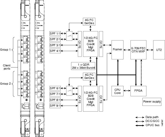
Figure 1 shows the MXP_MR_10DME_C and MXP_MR_10DME_L faceplates and block diagram.
Figure 1 MXP_MR_10DME_C and MXP_MR_10DME_L Faceplates and Block Diagram
Wavelength Identification
The card uses trunk lasers that are wavelocked, which allows the trunk transmitter to operate on the ITU grid effectively. Both the MXP_MR_10DME_C and MXP_MR_10DME_L cards implement the UT2 module. The MXP_MR_10DME_C card uses a C-band version of the UT2 and the MXP_MR_10DME_L card uses an L-band version.
Table 3 describes the required trunk transmit laser wavelengths for the MXP_MR_10DME_C card. The laser is tunable over 82 wavelengths in the C band at 50-GHz spacing on the ITU grid.
Table 4 describes the required trunk transmit laser wavelengths for the MXP_MR_10DME_L card. The laser is fully tunable over 80 wavelengths in the L band at 50-GHz spacing on the ITU grid.
Card-Level Indicators
Table 5 describes the three card-level LEDs on the MXP_MR_10DME_C and MXP_MR_10DME_L cards.
Port-Level Indicators
Table 6 describes the port-level LEDs on the MXP_MR_10DME_C and MXP_MR_10DME_L cards.
MXP_MR_10DME_C Card Specifications
The MXP_MR_10DME_C card has the following specifications:
•
Payload configuration
–
FC1G—Fibre Channel 1.06 Gbps
–
FC2G—Fibre Channel 2.125 Gbps
–
FC4G—Fibre Channel 4.25 Gbps
–
FICON1G—Fiber CON 1.06 Gbps (IBM signal)
–
FICON2G—Fiber CON 2.125 Gbps (IBM signal)
–
FICON4G—Fiber CON 4.25 Gbps (IBM signal)
–
ONE_GE—One Gigabit Ethernet 1.125 Gbps
–
Mixed configurations up to maximum line rate of 10.0 Gbps. See the Cisco ONS 15454 DWDM Reference Manual for more information on mixed-mode operation.
•
Client ports: 8x SFP
•
Line (trunk side)
–
Bit rate: 2.488 Gbps for OC-48/STM-16, 9.952 Gbps for OC-192/STM-64
–
Code: Scrambled NRZ
–
Fiber: 1310-nm single-mode or 850-nm multimode
–
Loopback modes: Terminal and facility
CautionYou must use a 20-dB fiber attenuator (15 to 25 dB) when working with the MXP_MR_10DME_C card in a loopback on the trunk port. Do not use direct fiber loopbacks with the MXP_MR_10DME_C cards. Using direct fiber loopbacks causes irreparable damage to the MXP_MR_10DME_C cards.
–
Connectors: LC
–
Compliance: Telcordia GR-253-CORE, Telcordia GR-2918-CORE, Issue 2, ITU-T G.957, and ITU-T 100-GHz grid standard G.692
•
Transmitter (trunk side)
–
Minimum output power: +3 dBm
–
Maximum output power: +6 dBm
–
Minimum SMSR: 30 dB
–
Minimum optical extinction ratio: 10 dB
–
41 wavelength tunability at 100-GHz spacing
–
Receiver maximum return reflectance (Rx return loss): -27 dB
–
Chromatic dispersion allowance: 5400 ps/nm, giving an optical power penalty < 2.0 dB
–
Minimum side mode suppression ratio: 30 dB
–
Wavelength stability (drift): +/- 25 picometers (pm)
Note
An optical device on the card keeps the laser wavelength locked as closely as possible to the ITU nominal value. The allowed drift is +/- 25 pm.
•
Receiver (trunk side)
Table 7 MXP_MR_10DME_C Receiver Trunk Side Specifications
FEC Applications OSNR1 Pre-FEC BER Post-FEC BER Input Power Sensitivity Chromatic Dispersion Tolerance Power Penalty OSNR PenaltyNone
23 dB
<10 exp - 12
—
-8 to -20 dBm
+/- 1200 ps/nm
2 dBm
—
19 dB
<10 exp - 12
—
-9 to -22 dBm
+/- 1000 ps/nm
2 dBm
—
FEC
10 dB
<10 exp - 5
<10 exp - 15
-8 to -18 dBm
+/- 800 ps/nm
—
1.5 dB
Enhanced FEC
19 dB
<10 exp - 4
<10 exp - 15
-8 to -26 dBm
+/- 800 ps/nm
2 dBm
2 dB
8 dB
<10 exp - 4
<10 exp - 15
-8 to -18 dBm
+/- 800 ps/nm
2 dBm
1.5 dB
1 OSNR defined with 0.5 nm RBW
•
Line (client side)
–
Bit rate: 1.06 Gbps to 2.125 Gbps per client
–
Code: Scrambled NRZ
–
Fiber: 1310-nm single-mode or 850-nm multimode
–
Maximum chromatic dispersion allowance: 1600 ps/nm
–
Loopback modes: Terminal and facility
–
Connectors: LC
–
Compliance: Telcordia GR-253-CORE, ITU-T G.707, ITU-T G.957
•
Transmitter (client side)
–
Maximum transmitter output power: -1 dBm
–
Minimum transmitter output power: -6 dBm
–
Center wavelength: 1290 to 1330 nm
–
Nominal wavelength: 1310 nm
–
Transmitter: DFB laser
•
Receiver (client side)
–
Maximum receiver level: -1 dBm at BER 1 * 10 exp - 12
–
Minimum receiver level: -14 dBm at BER 1 * 10 exp - 12
–
Receiver: APD
–
Link loss budget: 8 dB minimum, at BER = 1 * 10 exp - 12
–
Receiver input wavelength range: 1290 to 1605 nm
•
Environmental
–
Operating temperature: -5 to +40 degrees Celsius (+23 to +104 degrees Fahrenheit)
–
Operating humidity: 5 to 85 percent, noncondensing
–
Power consumption (maximum): 60 W, 1.25 A at -48 V, 204 BTU/hr
•
Environmental
–
Operating temperature: -5 to +40 degrees Celsius (+23 to +104 degrees Fahrenheit)
–
Operating humidity: 5 to 85 percent, noncondensing
–
Power consumption (maximum): 60 W, 1.25 A at -48 V, 204 BTU/hr
•
Dimensions
–
Height: 12.650 in. (321.3 mm)
–
Width: 0.716 in. (18.2 mm)
–
Depth: 9.000 in. (228.6 mm)
–
Depth with backplane connector: 9.250 in. (235 mm)
–
Weight not including clam shell: 2.25 lb (1.02 kg)
MXP_MR_10DME_L Card Specifications
The MXP_MR_10DME_L card has the following specifications:
•
Payload configuration
–
FC1G—Fibre Channel 1.06 Gbps
–
FC2G—Fibre Channel 2.125 Gbps
–
FC4G—Fibre Channel 4.25 Gbps
–
FICON1G—Fiber CON 1.06 Gbps (IBM signal)
–
FICON2G—Fiber CON 2.125 Gbps (IBM signal)
–
FICON4G—Fiber CON 4.25 Gbps (IBM signal)
–
ONE_GE—One Gigabit Ethernet 1.125 Gbps
–
Mixed configurations up to maximum line rate of 10.0 Gbps. See the Cisco ONS 15454 DWDM Reference Manual for more information on mixed-mode operation.
•
Client ports: 8x SFP
•
Line (trunk side)
–
Bit rate: 2.488 Gbps for OC-48/STM-16, 9.952 Gbps for OC-192/STM-64
–
Code: Scrambled NRZ
–
Fiber: 1310-nm single-mode or 850-nm multimode
–
Loopback modes: Terminal and facility
CautionYou must use a 20-dB fiber attenuator (15 to 25 dB) when working with the MXP_MR_10DME_L card in a loopback on the trunk port. Do not use direct fiber loopbacks with the MXP_MR_10DME_L cards. Using direct fiber loopbacks causes irreparable damage to the MXP_MR_10DME_L cards.
–
Connectors: LC
–
Compliance: Telcordia GR-253-CORE, Telcordia GR-2918-CORE, Issue 2, ITU-T G.957, and ITU-T 100-GHz grid standard G.692
•
Transmitter (trunk side)
–
Minimum output power: +3 dBm
–
Maximum output power: +6 dBm
–
Minimum SMSR: 30 dB
–
Minimum optical extinction ratio: 10.5 dB
–
40 wavelength tunability at 100-GHz spacing, 80 wavelength tunability at 50-GHz spacing
–
Receiver maximum return reflectance (Rx return loss): -27 dB
–
Chromatic dispersion allowance: 5400 ps/nm, giving an optical power penalty < 2.0 dB
–
Minimum side mode suppression ratio: 30 dB
–
Wavelength stability (drift): +/- 25 picometers (pm)
Note
An optical device on the card keeps the laser wavelength locked as closely as possible to the ITU nominal value. The allowed drift is +/- 25 pm.
•
Receiver (trunk side)
Table 8 MXP_MR_10DME_L Receiver Trunk Side Specifications
FEC Applications OSNR1 Pre-FEC BER Post-FEC BER Input Power Sensitivity Chromatic Dispersion Tolerance Power Penalty OSNR PenaltyNone
23 dB
<10 exp - 12
—
-8 to -19 dBm
+/- 1200 ps/nm
2 dBm
—
19 dB
<10 exp - 12
—
-9 to -19 dBm
+/- 1000 ps/nm
2 dBm
—
FEC
10 dB
<10 exp - 5
<10 exp - 15
-8 to -18 dBm
+/- 800 ps/nm
—
1.5 dB
Enhanced FEC
19 dB
<10 exp - 4
<10 exp - 15
-8 to -26 dBm
+/- 800 ps/nm
—
2 dB
8 dB
<10 exp - 4
<10 exp - 15
-8 to -18 dBm
+/- 800 ps/nm
—
1.5 dB
1 Optical Signal-to-Noise ratio (OSNR) defined with 0.5 nm Resolution Bandwidth (RBW)
•
Line (client side)
–
Bit rate: 1.06 Gbps to 2.125 Gbps per client
–
Code: Scrambled NRZ
–
Fiber: 1310-nm single-mode or 850-nm multimode
–
Maximum chromatic dispersion allowance: 1600 ps/nm
–
Loopback modes: Terminal and facility
–
Connectors: LC
–
Compliance: Telcordia GR-253-CORE, ITU-T G.707, ITU-T G.957
•
Transmitter (client side)
–
Maximum transmitter output power: -1 dBm
–
Minimum transmitter output power: -6 dBm
–
Center wavelength: 1290 to 1330 nm
–
Nominal wavelength: 1310 nm
–
Transmitter: DFB laser
•
Receiver (client side)
–
Maximum receiver level: -1 dBm at BER 1 * 10 exp - 12
–
Minimum receiver level: -14 dBm at BER 1 * 10 exp - 12
–
Receiver: APD
–
Link loss budget: 8 dB minimum, at BER = 1 * 10 exp - 12
–
Receiver input wavelength range: 1290 to 1605 nm
•
Environmental
–
Operating temperature: -5 to +40 degrees Celsius (+23 to +104 degrees Fahrenheit)
–
Operating humidity: 5 to 85 percent, noncondensing
–
Power consumption (maximum): 60 W, 1.25 A at -48 V, 204 BTU/hr
•
Environmental
–
Operating temperature: -5 to +40 degrees Celsius (+23 to +104 degrees Fahrenheit)
–
Operating humidity: 5 to 85 percent, noncondensing
–
Power consumption (maximum): 60 W, 1.25 A at -48 V, 204 BTU/hr
•
Dimensions
–
Height: 12.650 in. (321.3 mm)
–
Width: 0.716 in. (18.2 mm)
–
Depth: 9.000 in. (228.6 mm)
–
Depth with backplane connector: 9.250 in. (235 mm)
–
Weight not including clam shell: 2.25 lb (1.02 kg)
Install the MXP_MR_10DME_C and MXP_MR_10DME_L Cards
Warning
During this procedure, wear grounding wrist straps to avoid ESD damage to the card. Do not directly touch the backplane with your hand or any metal tool, or you could shock yourself. Statement 94
Warning
Class I (CDRH) and Class 1M (IEC) laser products. Statement 1055
Warning
Invisible laser radiation may be emitted from disconnected fibers or connectors. Do not stare into beams or view directly with optical instruments. Statement 272
Note
If protective clips are installed on the rear connectors of the cards, remove the clips before installing the cards.
Note
If you install a card incorrectly, the FAIL LED flashes continuously.
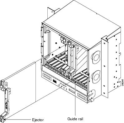
Figure 2 shows general card installation.
Figure 2 Installing a Card in the Cisco ONS 15454 SONET (ANSI) Shelf Assembly
Step 1
Display the card installation plan for the node using one of the following sources:
•
The Cisco MetroPlanner Site Dialog window for the node you are provisioning.
•
CTC node view with slots preprovisioned based on the Cisco MetroPlanner Site Dialog window.
•
Written slot plan. The plan must be based on the Cisco MetroPlanner Site Dialog window for your installation.
Step 2
Remove the card from its packaging, then remove the protective clips from the card's rear connectors.
Step 3
Open the card latches/ejectors.
Step 4
Use the latches/ejectors to firmly slide the card along the guide rails until the card plugs into the receptacle at the back of the slot.
Step 5
Verify that the card is inserted correctly and close the latches/ejectors on the card.
Note
It is possible to close the latches and ejectors when the card is not completely plugged into the chassis. Ensure that you cannot insert the card any further.
Step 6
Verify the LED activity:
•
The red FAIL LED turns on for 20 to 30 seconds.
•
The red FAIL LED blinks for 35 to 45 seconds.
•
All LEDs blink once and turn off for 5 to 10 seconds.
•
The ACT or ACT/STBY LED turns on. The SF LED can persist until all card ports connect to their far-end counterparts and a signal is present.
Step 7
If the card does not boot up properly, or the LED activity does not occur as described in Step 6, check the following:
•
When a physical card type does not match the type of card provisioned for that slot in CTC, the card might not boot. If the card does not boot, open CTC and ensure that the slot is not provisioned for a different card type before assuming that the card is faulty.
•
If the red FAIL LED does not turn on, check the power.
•
If you insert a card into a slot provisioned for a different card, all LEDs turn off.
•
If the red FAIL LED is on continuously or the LEDs behave erratically, the card is not installed properly. Remove the card and repeat Steps 3 to 6.
Stop. You have completed this procedure.
Related Documentation
•
Cisco ONS 15454 DWDM Reference Manual
•
Cisco ONS 15454 DWDM Procedure Guide
•
Cisco ONS 15454 DWDM Troubleshooting Guide
•
Cisco MetroPlanner DWDM Operations Guide
Obtaining Documentation
Cisco documentation and additional literature are available on Cisco.com. Cisco also provides several ways to obtain technical assistance and other technical resources. These sections explain how to obtain technical information from Cisco Systems.
Cisco.com
You can access the most current Cisco documentation at this URL:
http://www.cisco.com/techsupport
You can access the Cisco website at this URL:
You can access international Cisco websites at this URL:
http://www.cisco.com/public/countries_languages.shtml
Product Documentation DVD
Cisco documentation and additional literature are available in the Product Documentation DVD package, which may have shipped with your product. The Product Documentation DVD is updated regularly and may be more current than printed documentation.
The Product Documentation DVD is a comprehensive library of technical product documentation on portable media. The DVD enables you to access multiple versions of hardware and software installation, configuration, and command guides for Cisco products and to view technical documentation in HTML. With the DVD, you have access to the same documentation that is found on the Cisco website without being connected to the Internet. Certain products also have .pdf versions of the documentation available.
The Product Documentation DVD is available as a single unit or as a subscription. Registered Cisco.com users (Cisco direct customers) can order a Product Documentation DVD (product number DOC-DOCDVD=) from Cisco Marketplace at this URL:
http://www.cisco.com/go/marketplace/
Cisco Optical Networking Product Documentation CD-ROM
Optical networking-related documentation, including Cisco ONS 15xxx product documentation, is available in a CD-ROM package that ships with your product. The Optical Networking Product Documentation CD-ROM is updated periodically and may be more current than printed documentation.
Ordering Documentation
Beginning June 30, 2005, registered Cisco.com users may order Cisco documentation at the Product Documentation Store in the Cisco Marketplace at this URL:
http://www.cisco.com/go/marketplace/
Nonregistered Cisco.com users can order technical documentation from 8:00 a.m. to 5:00 p.m. (0800 to 1700) PDT by calling 1 866 463-3487 in the United States and Canada, or elsewhere by calling 011 408 519-5055. You can also order documentation by e-mail at tech-doc-store-mkpl@external.cisco.com or by fax at 1 408 519-5001 in the United States and Canada, or elsewhere at 011 408 519-5001.
Documentation Feedback
You can rate and provide feedback about Cisco technical documents by completing the online feedback form that appears with the technical documents on Cisco.com.
You can send comments about Cisco documentation to bug-doc@cisco.com.
You can submit comments by using the response card (if present) behind the front cover of your document or by writing to the following address:
Cisco Systems
Attn: Customer Document Ordering
170 West Tasman Drive
San Jose, CA 95134-9883We appreciate your comments.
Cisco Product Security Overview
Cisco provides a free online Security Vulnerability Policy portal at this URL:
http://www.cisco.com/en/US/products/products_security_vulnerability_policy.html
From this site, you can perform these tasks:
•
Report security vulnerabilities in Cisco products.
•
Obtain assistance with security incidents that involve Cisco products.
•
Register to receive security information from Cisco.
A current list of security advisories and notices for Cisco products is available at this URL:
If you prefer to see advisories and notices as they are updated in real time, you can access a Product Security Incident Response Team Really Simple Syndication (PSIRT RSS) feed from this URL:
http://www.cisco.com/en/US/products/products_psirt_rss_feed.html
Reporting Security Problems in Cisco Products
Cisco is committed to delivering secure products. We test our products internally before we release them, and we strive to correct all vulnerabilities quickly. If you think that you might have identified a vulnerability in a Cisco product, contact PSIRT:
•
Emergencies — security-alert@cisco.com
An emergency is either a condition in which a system is under active attack or a condition for which a severe and urgent security vulnerability should be reported. All other conditions are considered nonemergencies.
•
Nonemergencies — psirt@cisco.com
In an emergency, you can also reach PSIRT by telephone:
•
1 877 228-7302
•
1 408 525-6532
Tip
We encourage you to use Pretty Good Privacy (PGP) or a compatible product to encrypt any sensitive information that you send to Cisco. PSIRT can work from encrypted information that is compatible with PGP versions 2.x through 8.x.
Never use a revoked or an expired encryption key. The correct public key to use in your correspondence with PSIRT is the one linked in the Contact Summary section of the Security Vulnerability Policy page at this URL:
http://www.cisco.com/en/US/products/products_security_vulnerability_policy.html
The link on this page has the current PGP key ID in use.
Obtaining Technical Assistance
Cisco Technical Support provides 24-hour-a-day award-winning technical assistance. The Cisco Technical Support & Documentation website on Cisco.com features extensive online support resources. In addition, if you have a valid Cisco service contract, Cisco Technical Assistance Center (TAC) engineers provide telephone support. If you do not have a valid Cisco service contract, contact your reseller.
Cisco Technical Support & Documentation Website
The Cisco Technical Support & Documentation website provides online documents and tools for troubleshooting and resolving technical issues with Cisco products and technologies. The website is available 24 hours a day, at this URL:
http://www.cisco.com/techsupport
Access to all tools on the Cisco Technical Support & Documentation website requires a Cisco.com user ID and password. If you have a valid service contract but do not have a user ID or password, you can register at this URL:
http://tools.cisco.com/RPF/register/register.do
Note
Use the Cisco Product Identification (CPI) tool to locate your product serial number before submitting a web or phone request for service. You can access the CPI tool from the Cisco Technical Support & Documentation website by clicking the Tools & Resources link under Documentation & Tools. Choose Cisco Product Identification Tool from the Alphabetical Index drop-down list, or click the Cisco Product Identification Tool link under Alerts & RMAs. The CPI tool offers three search options: by product ID or model name; by tree view; or for certain products, by copying and pasting show command output. Search results show an illustration of your product with the serial number label location highlighted. Locate the serial number label on your product and record the information before placing a service call.
Submitting a Service Request
Using the online TAC Service Request Tool is the fastest way to open S3 and S4 service requests. (S3 and S4 service requests are those in which your network is minimally impaired or for which you require product information.) After you describe your situation, the TAC Service Request Tool provides recommended solutions. If your issue is not resolved using the recommended resources, your service request is assigned to a Cisco engineer. The TAC Service Request Tool is located at this URL:
http://www.cisco.com/techsupport/servicerequest
For S1 or S2 service requests or if you do not have Internet access, contact the Cisco TAC by telephone. (S1 or S2 service requests are those in which your production network is down or severely degraded.) Cisco engineers are assigned immediately to S1 and S2 service requests to help keep your business operations running smoothly.
To open a service request by telephone, use one of the following numbers:
Asia-Pacific: +61 2 8446 7411 (Australia: 1 800 805 227)
EMEA: +32 2 704 55 55
USA: 1 800 553-2447For a complete list of Cisco TAC contacts, go to this URL:
http://www.cisco.com/techsupport/contacts
Definitions of Service Request Severity
To ensure that all service requests are reported in a standard format, Cisco has established severity definitions.
Severity 1 (S1)—Your network is "down," or there is a critical impact to your business operations. You and Cisco will commit all necessary resources around the clock to resolve the situation.
Severity 2 (S2)—Operation of an existing network is severely degraded, or significant aspects of your business operation are negatively affected by inadequate performance of Cisco products. You and Cisco will commit full-time resources during normal business hours to resolve the situation.
Severity 3 (S3)—Operational performance of your network is impaired, but most business operations remain functional. You and Cisco will commit resources during normal business hours to restore service to satisfactory levels.
Severity 4 (S4)—You require information or assistance with Cisco product capabilities, installation, or configuration. There is little or no effect on your business operations.
Obtaining Additional Publications and Information
Information about Cisco products, technologies, and network solutions is available from various online and printed sources.
•
Cisco Marketplace provides a variety of Cisco books, reference guides, documentation, and logo merchandise. Visit Cisco Marketplace, the company store, at this URL:
http://www.cisco.com/go/marketplace/
•
Cisco Press publishes a wide range of general networking, training and certification titles. Both new and experienced users will benefit from these publications. For current Cisco Press titles and other information, go to Cisco Press at this URL:
•
Packet magazine is the Cisco Systems technical user magazine for maximizing Internet and networking investments. Each quarter, Packet delivers coverage of the latest industry trends, technology breakthroughs, and Cisco products and solutions, as well as network deployment and troubleshooting tips, configuration examples, customer case studies, certification and training information, and links to scores of in-depth online resources. You can access Packet magazine at this URL:
•
iQ Magazine is the quarterly publication from Cisco Systems designed to help growing companies learn how they can use technology to increase revenue, streamline their business, and expand services. The publication identifies the challenges facing these companies and the technologies to help solve them, using real-world case studies and business strategies to help readers make sound technology investment decisions. You can access iQ Magazine at this URL:
http://www.cisco.com/go/iqmagazine
or view the digital edition at this URL:
http://ciscoiq.texterity.com/ciscoiq/sample/
•
Internet Protocol Journal is a quarterly journal published by Cisco Systems for engineering professionals involved in designing, developing, and operating public and private internets and intranets. You can access the Internet Protocol Journal at this URL:
•
Networking products offered by Cisco Systems, as well as customer support services, can be obtained at this URL:
http://www.cisco.com/en/US/products/index.html
•
Networking Professionals Connection is an interactive website for networking professionals to share questions, suggestions, and information about networking products and technologies with Cisco experts and other networking professionals. Join a discussion at this URL:
http://www.cisco.com/discuss/networking
•
World-class networking training is available from Cisco. You can view current offerings at this URL:
http://www.cisco.com/en/US/learning/index.html
This document is to be used in conjunction with the documents listed in the "Related Documentation" section
© 2005 Cisco Systems, Inc. All rights reserved.
Printed in the USA on recycled paper containing 10% postconsumer waste.


