Installing the TXP_MR_10E_C and TXP_MR_10E_L Cards in the Cisco ONS 15454 SONET/SDH
Available Languages
Table Of Contents
Installing the TXP_MR_10E_C and TXP_MR_10E_L Cards in the Cisco ONS 15454 SONET/SDH
TXP_MR_10E_C and TXP_MR_10E_L Card Description
TXP_MR_10E_C Card Specifications
TXP_MR_10E_L Card Specifications
Install the TXP_MR_10E_C and TXP_MR_10E_L Cards
Obtaining Documentation and Submitting a Service Request
Installing the TXP_MR_10E_C and TXP_MR_10E_L Cards in the Cisco ONS 15454 SONET/SDH

Note
The terms "Unidirectional Path Switched Ring" and "UPSR" may appear in Cisco literature. These terms do not refer to using Cisco ONS 15xxx products in a unidirectional path switched ring configuration. Rather, these terms, as well as "Path Protected Mesh Network" and "PPMN," refer generally to Cisco's path protection feature, which may be used in any topological network configuration. Cisco does not recommend using its path protection feature in any particular topological network configuration.
Product Names: 15454-10EMRC TXP, 15454-10EMRL TXP
This document provides a card description, specifications, and installation procedure for the MXP_MR_10E_C and MXP_MR_10E_L cards. These cards are compatible with the ONS 15454 SONET (ANSI) and the ONS 15454 SDH (ETSI) shelf assemblies. As appropriate, use this document in conjunction with the Cisco ONS 15454 DWDM Procedure Guide, the Cisco ONS 15454 DWDM Reference Manual, and the Cisco ONS 15454 DWDM Troubleshooting Guide.
This document contains the following sections:
•
•
•
•
•
TXP_MR_10E_C and TXP_MR_10E_L Card Description
The TXP_MR_10E_C and TXP_MR_10E_L cards are multirate transponders for the ONS 15454 platform. The cards are fully backward compatible with the TXP_MR_10G and TXP_MR_10E cards. They process one 10-Gbps signal (client side) into one 100-GHz DWDM signal (trunk side). The TXP_MR_10E_C is tunable over the entire set of C-band wavelength channels (82 channels spaced at 50 GHz on the ITU grid). The TXP_MR_10E_L is tunable over the entire set of L-band wavelength channels (80 channels spaced at 50 GHz on the ITU grid) and is well suited for use in networks that employ DS fiber or SMF-28 single-mode fiber. You can install TXP_MR_10E_C and TXP_MR_10E_L cards in Slots 1 to 6 and 12 to 17.
Key Features
The key features of the TXP_MR_10E_C and TXP_MR_10E_L cards are:
•
–
–
–
•
•
•
•
•
–
–
–
•
•
Client and Trunk Ports
The TXP_MR_10E card features a universal transponder 2 (UT2) 1550-nm tunable laser (C band) or a UT2 1580-nm tunable laser (L band) for the trunk port and a separately orderable ONS-XC-10G-S1 1310-nm laser XFP module for the client port. On its faceplate, the TXP_MR_10E_C and TXP_MR_10E_L cards contain two transmit and receive connector pairs, one for the trunk port and one for the client port. Each connector pair is labeled.
DWDM Trunk Interface
On the trunk side, the TXP_MR_10E_C and TXP_MR_10E_L cards provide a 10-Gbps STM-64/OC-192 interface. There are 80 tunable channels available in the 1550-nm C band or 82 tunable channels available in the 1580-nm L band on the 50-GHz ITU grid for the DWDM interface. The TXP_MR_10E_C and TXP_MR_10E_C cards provide 3R transponder functionality for this 10-Gbps trunk interface. Therefore, the card is suited for use in long-range amplified systems. The DWDM interface is compliant with ITU-T G.707, ITU-T G.709, and Telcordia GR-253-CORE standards.
The DWDM trunk port operates at a rate that is dependent on the input signal and the presence or absence of the ITU-T G.709 Digital Wrapper/FEC. The possible trunk rates are:
•
•
•
•
The maximum system reach in filterless applications without the use of optical amplification or regenerators is nominally rated at 23 dB over C-SMF fiber. This rating is not a product specification, but is given for informational purposes. It is subject to change.
Client-to-Trunk Mapping
The TXP_MR_10E_C and TXP_MR_10E_L cards can perform ODU2-to-OCh mapping, which allows operators to provision data payloads in a standard way across 10-Gbps optical links.
Digital wrappers that define client side interfaces are called ODU2 entities in ITU-T G.709. Digital wrappers that define trunk side interfaces are called OCh in ITU-T G.709. ODU2 digital wrappers can include G-MPLS signaling extensions to ITU-T G.709 (such as LSP and G-PID values) to define client interfaces and payload protocols.
Wavelength Identification
The TXP_MR_10E_C card is tunable across 82 wavelengths in the C-band frequency plan, with channels on the ITU 50-GHz grid, as shown in Table 1.
The TXP_MR_10E_L card is tunable across 80 wavelengths in the L band frequency plan, with channels on the ITU 50-GHz grid, as shown in Table 2.
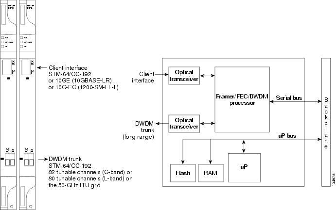
Faceplate and Block Diagram
Figure 1 shows the TXP_MR_10E_C and TXP_MR_10E_L faceplates and block diagram.
Figure 1 TXP_MR_10E_C and TXP_MR_10E_L Faceplate and Block Diagram
Card Level Indicators
Table 3 describes the three card-level LEDs on the TXP_MR_10E_C and TXP_MR_10E_L cards.
Port-Level Indicators
Table 4 lists the four port-level LEDs on the TXP_MR_10E_C and TXP_MR_10E_L cards.
TXP_MR_10E_C Card Specifications
The TXP_MR_10E_C card has the following specifications:
•
–
–
–
–
–

Caution
–
–
•
–
–
–
–
Note
•
Table 5 TXP_MR_10E_C Receiver Trunk Side Specifications
30 dB
Off
<10 exp - 12
N/A
- 8 to - 20 dBm
+/- 1200 ps/nm
26 dB
Off
<10 exp - 12
N/A
- 8 to - 20 dBm
+ - 1000 ps/nm
26 dB
Off
<10 exp - 12
N/A
- 8 to - 22 dBm
—
17 dB
Standard
<10 exp - 5
<10 exp - 15
- 8 to - 18 dBm
+/- 800 ps/nm
15 dB
Standard
<10 exp - 5
<10 exp - 15
- 8 to - 18 dBm
—
15 dB
Enhanced
<7 x 10 exp - 4
<10 exp - 15
- 8 to - 18 dBm
+/- 800 ps/nm
14 dB
Enhanced
<7 x 10 exp - 4
<10 exp - 15
- 8 to - 18 dBm
—
1 Optical Signal-to-Noise ratio (OSNR) defined with 0.1 nm Resolution Bandwidth (RBW)
2 Receiver filter bandwidth greater than or equal to 180 pm (at - 3 dBm)
–
–
BER = 1 * 10 exp - 12 including dispersion–
•
–
–
–
–
–
–
–
–
•
–
–
–
–
–
•
–
–
–
–
–
•
–
–
–
•
–
–
–
–
–
TXP_MR_10E_L Card Specifications
The TXP_MR_10E_L card has the following specifications:
•
–
–
–
–
–
Caution
–
–
•
–
–
–
–
Note
•
Table 6 TXP_MR_10E_L Receiver Trunk Side Specifications
30 dB
Off
<10 exp - 12
N/A
- 8 to - 20 dBm
+/- 1200 ps/nm
26 dB
Off
<10 exp - 12
N/A
- 8 to - 20 dBm
+ - 1000 ps/nm
26 dB
Off
<10 exp - 12
N/A
- 8 to - 22 dBm
—
17 dB
Standard
<10 exp - 5
<10 exp - 15
- 8 to - 18 dBm
+/- 800 ps/nm
15 dB
Standard
<10 exp - 5
<10 exp - 15
- 8 to - 18 dBm
—
15 dB
Enhanced
<7 x 10 exp - 4
<10 exp - 15
- 8 to - 18 dBm
+/- 800 ps/nm
14 dB
Enhanced
<7 x 10 exp - 4
<10 exp - 15
- 8 to - 18 dBm
—
1 Optical Signal-to-Noise ratio (OSNR) defined with 0.1 nm Resolution Bandwidth (RBW)
2 Receiver filter bandwidth greater than or equal to 180 pm (at - 3 dBm)
–
–
BER = 1 * 10 exp - 12 including dispersion–
•
–
–
–
–
–
–
–
–
•
–
–
–
–
–
•
–
–
–
–
–
•
–
–
–
•
–
–
–
–
–
Install the TXP_MR_10E_C and TXP_MR_10E_L Cards

Warning
Warning
Warning
Note
Note
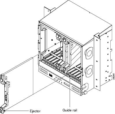
Figure 2 shows general card installation.
Figure 2 Installing a Card in the Cisco ONS 15454 SONET (ANSI) SHelf Assembly
Step 1
•
•
•
Step 2
Step 3
Step 4
Step 5
Note
Step 6
•
•
•
•
Step 7
•
•
•
•
Stop. You have completed this procedure.
Related Documentation
•
•
•
•
Obtaining Documentation and Submitting a Service Request
For information on obtaining documentation, submitting a service request, and gathering additional information, see the monthly What's New in Cisco Product Documentation, which also lists all new and revised Cisco technical documentation, at:
http://www.cisco.com/en/US/docs/general/whatsnew/whatsnew.html
Subscribe to the What's New in Cisco Product Documentation as an RSS feed and set content to be delivered directly to your desktop using a reader application. The RSS feeds are a free service. Cisco currently supports RSS Version 2.0.
This document is to be used in conjunction with the documents listed in the "Related Documentation" section
© 2005-2007 Cisco Systems, Inc. All rights reserved.
Printed in the USA on recycled paper containing 10% postconsumer waste.

 Feedback