Guest

Cisco ONS 15400 Series

Installing the 32WSS-L Card in the Cisco ONS 15454 SONET/SDH

Table Of Contents

Installing the 32WSS-L Card in the Cisco ONS 15454 SONET/SDH

32WSS-L Card Description

Faceplate

Block Diagrams

Power Monitoring

Channel Plan

32WSS-L Card Level Indicators

32WSS-L Port-Level Indicators

32WSS-L Card Specifications

Install the 32WSS-L Card

Related Documentation

Obtaining Documentation

Cisco.com

Product Documentation DVD

Cisco Optical Networking Product Documentation CD-ROM

Ordering Documentation

Documentation Feedback

Cisco Product Security Overview

Reporting Security Problems in Cisco Products

Obtaining Technical Assistance

Cisco Technical Support & Documentation Website

Submitting a Service Request

Definitions of Service Request Severity

Obtaining Additional Publications and Information


Installing the 32WSS-L Card in the Cisco ONS 15454 SONET/SDH


Product Name: 15454-WSS-L

This document provides a card description, specifications, and installation procedure for the dense wavelength division multiplexer (DWDM) 32WSS-L card. The 32WSS-L card is compatible with Cisco ONS 15454 SONET (ANSI) and Cisco ONS 15454 SDH (ETSI) shelf assemblies. Use this document in conjunction with the Cisco ONS 15454 DWDM Procedure Guide when working with 32WSS-L cards.

This document contains the following sections:

32WSS-L Card Description

32WSS-L Card Specifications

Install the 32WSS-L Card

Related Documentation

Obtaining Documentation

Documentation Feedback

Cisco Product Security Overview

Obtaining Technical Assistance

Obtaining Additional Publications and Information

32WSS-L Card Description

The 32-Channel Wavelength Selective Switch L-Band (32WSS-L) card performs channel add/drop processing within the ONS 15454 DWDM node. The 32WSS-L works in conjunction with the 32DMX-L to implement ROADM functionality within the L band (1570 to 1620 nm). The 32WSS-L card is well suited for use in networks that employ DS fiber or SMF-28 single-mode fiber. Equipped with ROADM functionality, a DWDM node can be configured to add or drop individual optical channels using Cisco Transport Controller (CTC), Cisco MetroPlanner, and Cisco Transport Manager (CTM).

An ROADM node utilizes two 32WSS-L cards (two slots each) and two 32DMX-L cards (one slot each), for a total of six slots in the chassis. For a diagram of a typical ROADM configuration, see the Cisco ONS 15454 DWDM Reference Manual. The two-slot 32WSS-L card can be installed in Slots 1 and 2, 3 and 4, 5 and 6, 12 and 13, 14 and 15, or 16 and 17.

The 32WSS-L has six types of ports:

ADD RX ports (1 to 32): These ports are used for adding channels. Each add channel is associated with an individual switch element that selects whether an individual channel is added. Each add port has optical power regulation provided by a VOA.

EXP RX port: The EXP RX port receives an optical signal from another 32WSS-L module in the same network element (NE).

EXP TX port: The EXP TX port sends an optical signal to the other 32WSS-L module within the NE.

COM TX port: The COM TX port sends an aggregate optical signal to a booster amplifier card (for example, OPT-BST) for transmission outside of the NE.

COM RX port: The COM RX port receives the optical signal from a preamplifier and sends it to the optical splitter.

DROP TX port: The DROP TX port sends the drop channels to the 32DMX-L card where the channels are further processed and dropped.

A terminal node can be configured using only a 32WSS-L card and a 32DMX-L card plugged into the east or west side of the shelf.

Faceplate

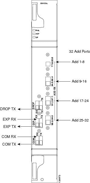
Figure 1 shows the 32WSS-L module front panel and identifies the traffic flow through the ports.

Figure 1 32WSS-L Faceplate

Block Diagrams

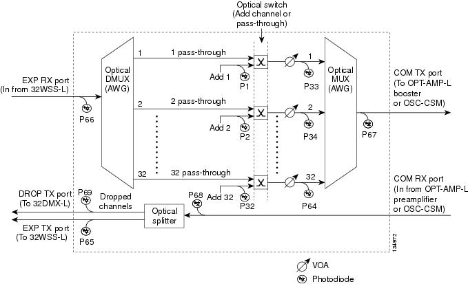
Figure 2 provides a high-level functional block diagram of the 32WSS-L card.

Figure 2 32WSS-L Block Diagram

Aggregate optical signals that enter the EXP RX and COM RX ports are processed in two ways. The optical processing stages are shown in Figure 3, which provides a detailed optical functional diagram of the 32WSS-L card.

Figure 3 32WSS-L Optical Functional Diagram

The EX PORT and COM PORT operate as follows:

EXP RX Port Add Channel/Pass-through Processing

The incoming optical signal is received at the EXP RX port from the other 32WSS-L module within the NE. The incoming aggregate optical signal is demultiplexed into 32 individual wavelength components, or channels. Then each channel is individually processed by the optical switch, which does add/pass-through processing. Under software control, the switch either selects the optical channel coming in from the demultiplexer (the pass-through channel) or it selects the external ADD channel. If the ADD port channel is selected, the optical signal coming from the demultiplexer is blocked, and the ADD channel is transmitted in its place.

After the optical switch stage, all of the channels are multiplexed together into an aggregate optical signal, which is sent out on the COM TX port. The output is typically connected to an OPT-AMP-L (in the event a booster amplifier is needed) or to an OSC-CSM (if no amplification is needed).

COM RX Port Optical Splitter Processing

The incoming optical signal received at the COM RX port is applied to the optical splitter within the 32WSS-L card. Channels that are designated to be dropped are diverted optically to the DROP TX port by the splitter. The DROP TX port on the 32WSS-L is typically connected to the COM RX port of the 32DMX-L where the drop channels are dropped. Channels that are not dropped pass through the optical splitter and flow out of the EXP TX port of the 32WSS-L card. This optical signal is typically connected to the other 32WSS-L module within the NE.

Power Monitoring

Physical photodiodes P1 through P69 monitor the power for the 32WSS-L card. The returned power level values are calibrated to the ports as shown in Table 1.

Table 1 32WSS-L Port Calibrations

Photodiode
CTC Type Name
Calibrated to Port

P1-P32

ADD (Power)

COM TX

ADD (Power ADD)

ADD RX

P33-P64

PASS THROUGH

COM TX

P65

OUT EXP

EXP TX

P66

IN EXP

EXP RX

P67

OUT COM

COM TX

P68

IN COM

COM RX

P69

DROP

DROP TX


Channel Plan

The 32WSS-L card uses 32 channels on the ITU 100-GHz grid in a banded configuration (see Table 2).

Table 2 32WSS-L Channel Plan  

Band ID
Channel Label
Frequency (THz)
Wavelength (nm)

B77.8

77.8

190

1577.86

78.6

189.9

1578.69

79.5

189.8

1579.52

80.3

189.7

1580.35

B81.1

81.1

189.6

1581.18

82.0

189.5

1582.02

82.8

189.4

1582.85

83.6

189.3

1583.69

B84.5

84.5

189.2

1584.53

85.3

189.1

1585.36

86.2

189

1586.20

87.0

188.9

1587.04

B87.8

87.8

188.8

1587.88

88.7

188.7

1588.73

89.5

188.6

1589.57

90.4

188.5

1590.41

B91.2

91.2

188.4

1591.26

92.1

188.3

1592.10

92.9

188.2

1592.95

93.7

188.1

1593.79

B94.6

94.6

188

1594.64

95.4

187.9

1595.49

96.3

187.8

1596.34

97.1

187.7

1597.19

B98.0

98.0

187.6

1598.04

98.8

187.5

1598.89

99.7

187.4

1599.75

00.6

187.3

1600.60

B01.4

01.4

187.2

1601.46

02.3

187.1

1602.31

03.1

187

1603.17

04.0

186.9

1604.03


32WSS-L Card Level Indicators

Table 3 describes the three card-level LED indicators on the 32WSS-L card.

Table 3 32WSS-L Card-Level Indicators  

Card-Level Indicators
Description

Red FAIL LED

The red FAIL LED indicates that the card's processor is not ready or that there is an internal hardware failure. Replace the card if the red FAIL LED persists.

Green ACT LED

The green ACT LED indicates that the 32WSS-L card is carrying traffic or is traffic-ready.

Amber SF LED

The amber SF LED indicates a signal failure on one or more of the card's ports. The amber SF LED also illuminates when the transmit and receive fibers are incorrectly connected. When the fibers are properly connected, the light turns off.


32WSS-L Port-Level Indicators

You can find the status of the 32WSS-L card's ports using the LCD screen on the ONS 15454 ANSI fan-tray assembly. Use the LCD to view the status of any port or card slot; the screen displays the number and severity of alarms for a given port or slot.

The 32WSS-L card has five sets of ports located on the faceplate. COM RX is the line input, COM TX is the line output, EXP RX is the port where a channel can be added or passed through, EXP TX is the port that passes through the channels that are not dropped, and DROP TX is the port for the dropped channels. The xx.x to yy.y TX ports represent the four groups of eight channels ranging from the xx.x wavelength to the yy.y wavelenth according to the channel plan.

32WSS-L Card Specifications

The 32WSS-L card optical specifications are listed in Table 4.


Note For power specifications, see Cisco ONS 15454 DWDM Reference Manual.


Table 4 32WSS-L Card Optical Specifications 

Parameter
Note
Condition
Min
Typical
Max
Units

-0.1 dB bandwidth

All SOP and within whole operating temperature range, connectors included, and for maximum VOA operating attenuation.

EXP RX => COM TX

+/-/57

pm

-0.25 dB bandwidth

+/-/61

+/-/89

-0.5 dB bandwidth

+/-91

+/-/116

-1.0 dB bandwidth

+/-135

+/-/149

-0.1 dB bandwidth

Add 1, 32 => COM TX

+/-32

+/-/69

-0.25 dB bandwidth

+/-98

+/-/129

-0.5 dB bandwidth

+/-135

+/-/161

-1.0 dB bandwidth

+/-160

+/-/201

Insertion loss

All SOP, any optical switch state, and within whole operating temperature range, connectors included.

EXP RX => COM TX

9.7

11.3

dB

COM RX => EXP TX

1.4

1.6

dB

Add 1, 32 => COM TX

6.2

8.0

dB

COM RX => DROP TX

6.0

8.0

8.5

dB

VOA dynamic range

EXP RX => COM TX

20

25

dB

Add 1, 32 => COM TX

25

25

dB

Maximum optical input power

300

mW


The 32WSS-L card has the following additional specifications:

Environmental

Operating temperature:

C-Temp: -5 to +55 degrees Celsius (+23 to +131 degrees Fahrenheit)

Operating humidity: 5 to 95 percent RH

Dimensions

Height: 12.65 in. (321.3 mm)

Width: 1.84 in. (46.8 mm)

Depth: 9.00 in. (228.6 mm)

Install the 32WSS-L Card


Warning During this procedure, wear grounding wrist straps to avoid ESD damage to the card. Do not directly touch the backplane with your hand or any metal tool, or you could shock yourself. Statement 94


Warning Class 1M laser radiation when open. Do not view directly with optical instruments. Statement 1053


Warning Invisible laser radiation may be emitted from the end of the unterminated fiber cable or connector. Do not view directly with optical instruments. Viewing the laser output with certain optical instruments (for example, eye loupes, magnifiers, and microscopes) within a distance of 100 mm may pose an eye hazard. Statement 1056


Caution Always use the supplied ESD wristband when working with a powered ONS 15454. Plug the wristband cable into the ESD jack located on the lower-right outside edge of the shelf assembly.


Note If protective clips are installed on the card connectors, remove the clips before installing the cards.


Note If you install a card incorrectly, the FAIL LED flashes continuously.


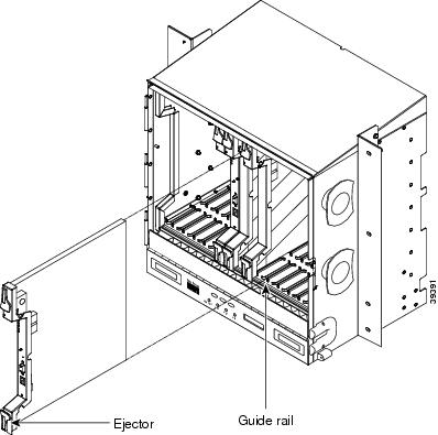
Figure 4 shows general card installation.

Figure 4 Installing a Card in the Cisco ONS 15454 (ANSI)


Step 1 Display the card installation plan for the node using one of the following sources:

The Cisco MetroPlanner Site Dialog window for the node you are provisioning.

CTC node view with slots preprovisioned based on the Cisco MetroPlanner Site Dialog window.

Written slot plan. The plan must be based on the Cisco MetroPlanner Site Dialog window for your installation.

Step 2 Remove the 32WSS-L card from its packaging, then remove the protective caps from the card's rear connectors.

Step 3 Open the card latches/ejectors.

Step 4 Use the latches/ejectors to firmly slide the card along the slot guide rails until the card plugs into the receptacle at the back of the slot.

Step 5 Verify that the card is inserted correctly and close the latches/ejectors on the card.


Note It is possible to close the latches/ejectors when the card is not completely plugged into the backplane. Ensure that you cannot insert the card any further.


Step 6 Verify the LED activity:

The FAIL LED turns on for approximately 35 seconds.

The FAIL LED blinks for approximately 40 seconds.

All LEDs turn on and then turn off within 5 seconds.

If new software is being downloaded to the card, the ACT and SF LEDs blink for 20 seconds to 3.5 minutes, depending on the card type.

The ACT LED turns on.

The signal fail (SF) LED stays on until all card ports connect to their far-end counterparts and a signal is present.

Step 7 If the card does not boot up properly, or the LED activity does not mimic Step 6, check the following:

When a physical card type does not match the type of card provisioned for that slot in CTC, the card might not boot. If a 32WSS-L card does not boot, open CTC and ensure that the slot is not provisioned for a different card type before assuming that the card is faulty.

If the red FAIL LED does not turn on, check the power.

If you insert a card into a slot provisioned for a different card, all LEDs turn off.

If the red FAIL LED is on continuously or the LEDs behave erratically, the card is not installed. Remove the card and repeat Steps 3 to 7. If the card does not boot up properly the second time, it may be defective. Contact your next level of support.


Note The DWDM node type is determined by the cards that are installed. For example, if two 32DMX-O and two 32MUX-O cards are installed but no AD-xC or AD-xB cards are installed, CTC considers the node a hub node. However, if one 32DMX-O and one 32MUX-O card is installed with no AD-xC or AD-xB cards, CTC considers the node a terminal node. For more information, refer to the iCisco ONS 15454 DWDM Reference Manual


Related Documentation

Cisco ONS 15454 DWDM Reference Manual

Cisco ONS 15454 DWDM Procedure Guide

Cisco ONS 15454 DWDM Troubleshooting Guide

Cisco MetroPlanner DWDM Operations Guide

Obtaining Documentation

Cisco documentation and additional literature are available on Cisco.com. Cisco also provides several ways to obtain technical assistance and other technical resources. These sections explain how to obtain technical information from Cisco Systems.

Cisco.com

You can access the most current Cisco documentation at this URL:

http://www.cisco.com/techsupport

You can access the Cisco website at this URL:

http://www.cisco.com

You can access international Cisco websites at this URL:

http://www.cisco.com/public/countries_languages.shtml

Product Documentation DVD

Cisco documentation and additional literature are available in the Product Documentation DVD package, which may have shipped with your product. The Product Documentation DVD is updated regularly and may be more current than printed documentation.

The Product Documentation DVD is a comprehensive library of technical product documentation on portable media. The DVD enables you to access multiple versions of hardware and software installation, configuration, and command guides for Cisco products and to view technical documentation in HTML. With the DVD, you have access to the same documentation that is found on the Cisco website without being connected to the Internet. Certain products also have .pdf versions of the documentation available.

The Product Documentation DVD is available as a single unit or as a subscription. Registered Cisco.com users (Cisco direct customers) can order a Product Documentation DVD (product number DOC-DOCDVD=) from Cisco Marketplace at this URL:

http://www.cisco.com/go/marketplace/

Cisco Optical Networking Product Documentation CD-ROM

Optical networking-related documentation, including Cisco ONS 15xxx product documentation, is available in a CD-ROM package that ships with your product. The Optical Networking Product Documentation CD-ROM is updated periodically and may be more current than printed documentation.

Ordering Documentation

Beginning June 30, 2005, registered Cisco.com users may order Cisco documentation at the Product Documentation Store in the Cisco Marketplace at this URL:

http://www.cisco.com/go/marketplace/

Nonregistered Cisco.com users can order technical documentation from 8:00 a.m. to 5:00 p.m. (0800 to 1700) PDT by calling 1 866 463-3487 in the United States and Canada, or elsewhere by calling 011 408 519-5055. You can also order documentation by e-mail at tech-doc-store-mkpl@external.cisco.com or by fax at 1 408 519-5001 in the United States and Canada, or elsewhere at 011 408 519-5001.

Documentation Feedback

You can rate and provide feedback about Cisco technical documents by completing the online feedback form that appears with the technical documents on Cisco.com.

You can send comments about Cisco documentation to bug-doc@cisco.com.

You can submit comments by using the response card (if present) behind the front cover of your document or by writing to the following address:

Cisco Systems
Attn: Customer Document Ordering
170 West Tasman Drive
San Jose, CA 95134-9883

We appreciate your comments.

Cisco Product Security Overview

Cisco provides a free online Security Vulnerability Policy portal at this URL:

http://www.cisco.com/en/US/products/products_security_vulnerability_policy.html

From this site, you can perform these tasks:

Report security vulnerabilities in Cisco products.

Obtain assistance with security incidents that involve Cisco products.

Register to receive security information from Cisco.

A current list of security advisories and notices for Cisco products is available at this URL:

http://www.cisco.com/go/psirt

If you prefer to see advisories and notices as they are updated in real time, you can access a Product Security Incident Response Team Really Simple Syndication (PSIRT RSS) feed from this URL:

http://www.cisco.com/en/US/products/products_psirt_rss_feed.html

Reporting Security Problems in Cisco Products

Cisco is committed to delivering secure products. We test our products internally before we release them, and we strive to correct all vulnerabilities quickly. If you think that you might have identified a vulnerability in a Cisco product, contact PSIRT:

Emergencies — security-alert@cisco.com

An emergency is either a condition in which a system is under active attack or a condition for which a severe and urgent security vulnerability should be reported. All other conditions are considered nonemergencies.

Nonemergencies — psirt@cisco.com

In an emergency, you can also reach PSIRT by telephone:

1 877 228-7302

1 408 525-6532


Tip We encourage you to use Pretty Good Privacy (PGP) or a compatible product to encrypt any sensitive information that you send to Cisco. PSIRT can work from encrypted information that is compatible with PGP versions 2.x through 8.x.

Never use a revoked or an expired encryption key. The correct public key to use in your correspondence with PSIRT is the one linked in the Contact Summary section of the Security Vulnerability Policy page at this URL:

http://www.cisco.com/en/US/products/products_security_vulnerability_policy.html

The link on this page has the current PGP key ID in use.


Obtaining Technical Assistance

Cisco Technical Support provides 24-hour-a-day award-winning technical assistance. The Cisco Technical Support & Documentation website on Cisco.com features extensive online support resources. In addition, if you have a valid Cisco service contract, Cisco Technical Assistance Center (TAC) engineers provide telephone support. If you do not have a valid Cisco service contract, contact your reseller.

Cisco Technical Support & Documentation Website

The Cisco Technical Support & Documentation website provides online documents and tools for troubleshooting and resolving technical issues with Cisco products and technologies. The website is available 24 hours a day, at this URL:

http://www.cisco.com/techsupport

Access to all tools on the Cisco Technical Support & Documentation website requires a Cisco.com user ID and password. If you have a valid service contract but do not have a user ID or password, you can register at this URL:

http://tools.cisco.com/RPF/register/register.do


Note Use the Cisco Product Identification (CPI) tool to locate your product serial number before submitting a web or phone request for service. You can access the CPI tool from the Cisco Technical Support & Documentation website by clicking the Tools & Resources link under Documentation & Tools. Choose Cisco Product Identification Tool from the Alphabetical Index drop-down list, or click the Cisco Product Identification Tool link under Alerts & RMAs. The CPI tool offers three search options: by product ID or model name; by tree view; or for certain products, by copying and pasting show command output. Search results show an illustration of your product with the serial number label location highlighted. Locate the serial number label on your product and record the information before placing a service call.


Submitting a Service Request

Using the online TAC Service Request Tool is the fastest way to open S3 and S4 service requests. (S3 and S4 service requests are those in which your network is minimally impaired or for which you require product information.) After you describe your situation, the TAC Service Request Tool provides recommended solutions. If your issue is not resolved using the recommended resources, your service request is assigned to a Cisco engineer. The TAC Service Request Tool is located at this URL:

http://www.cisco.com/techsupport/servicerequest

For S1 or S2 service requests or if you do not have Internet access, contact the Cisco TAC by telephone. (S1 or S2 service requests are those in which your production network is down or severely degraded.) Cisco engineers are assigned immediately to S1 and S2 service requests to help keep your business operations running smoothly.

To open a service request by telephone, use one of the following numbers:

Asia-Pacific: +61 2 8446 7411 (Australia: 1 800 805 227)
EMEA: +32 2 704 55 55
USA: 1 800 553-2447

For a complete list of Cisco TAC contacts, go to this URL:

http://www.cisco.com/techsupport/contacts

Definitions of Service Request Severity

To ensure that all service requests are reported in a standard format, Cisco has established severity definitions.

Severity 1 (S1)—Your network is "down," or there is a critical impact to your business operations. You and Cisco will commit all necessary resources around the clock to resolve the situation.

Severity 2 (S2)—Operation of an existing network is severely degraded, or significant aspects of your business operation are negatively affected by inadequate performance of Cisco products. You and Cisco will commit full-time resources during normal business hours to resolve the situation.

Severity 3 (S3)—Operational performance of your network is impaired, but most business operations remain functional. You and Cisco will commit resources during normal business hours to restore service to satisfactory levels.

Severity 4 (S4)—You require information or assistance with Cisco product capabilities, installation, or configuration. There is little or no effect on your business operations.

Obtaining Additional Publications and Information

Information about Cisco products, technologies, and network solutions is available from various online and printed sources.

Cisco Marketplace provides a variety of Cisco books, reference guides, documentation, and logo merchandise. Visit Cisco Marketplace, the company store, at this URL:

http://www.cisco.com/go/marketplace/

Cisco Press publishes a wide range of general networking, training and certification titles. Both new and experienced users will benefit from these publications. For current Cisco Press titles and other information, go to Cisco Press at this URL:

http://www.ciscopress.com

Packet magazine is the Cisco Systems technical user magazine for maximizing Internet and networking investments. Each quarter, Packet delivers coverage of the latest industry trends, technology breakthroughs, and Cisco products and solutions, as well as network deployment and troubleshooting tips, configuration examples, customer case studies, certification and training information, and links to scores of in-depth online resources. You can access Packet magazine at this URL:

http://www.cisco.com/packet

iQ Magazine is the quarterly publication from Cisco Systems designed to help growing companies learn how they can use technology to increase revenue, streamline their business, and expand services. The publication identifies the challenges facing these companies and the technologies to help solve them, using real-world case studies and business strategies to help readers make sound technology investment decisions. You can access iQ Magazine at this URL:

http://www.cisco.com/go/iqmagazine

or view the digital edition at this URL:

http://ciscoiq.texterity.com/ciscoiq/sample/

Internet Protocol Journal is a quarterly journal published by Cisco Systems for engineering professionals involved in designing, developing, and operating public and private internets and intranets. You can access the Internet Protocol Journal at this URL:

http://www.cisco.com/ipj

Networking products offered by Cisco Systems, as well as customer support services, can be obtained at this URL:

http://www.cisco.com/en/US/products/index.html

Networking Professionals Connection is an interactive website for networking professionals to share questions, suggestions, and information about networking products and technologies with Cisco experts and other networking professionals. Join a discussion at this URL:

http://www.cisco.com/discuss/networking

World-class networking training is available from Cisco. You can view current offerings at this URL:

http://www.cisco.com/en/US/learning/index.html


Printed in the USA on recycled paper containing 10% postconsumer waste.