Installing the Cisco ONS 15454 Fan-Tray Assembly (FTA2)
Available Languages
Table Of Contents
Installing the Cisco ONS 15454 Fan-Tray Assembly
Fan-Tray Assembly Compatibility
Fan-Tray Assembly Installation
Fan-Tray Air Filter Installation
Install the Fan-Tray Air Filter in the External Brackets
Install the Fan-Tray Air Filter Beneath the Fan-Tray Assembly
Obtaining Documentation and Submitting a Service Request
Installing the Cisco ONS 15454 Fan-Tray Assembly
Product Number: 15454-FTA2 FAN MODULEThe 15454-FTA2 fan-tray assembly is a removable drawer located at the bottom of the ONS 15454 front compartment that holds fans and fan-control circuitry. The front door of the ONS 15454 can be opened and left in place when removing or installing the fan-tray assembly. After you install the fan-tray assembly, you should only need to access it if a fan failure occurs or you need to replace or clean the fan-tray air filter installed beneath it. For more information on the fan-tray air filter, see the "Fan-Tray Air Filter Installation" section.
If one or more fans fail on the fan-tray assembly, replace the entire assembly. You cannot replace individual fans. The red Fan Fail LED on the front of the fan tray illuminates when one or more fans fail. The red Fan Fail LED clears after you install a working fan tray.
Fan speed is controlled by TCC/TCC+ card temperature sensors. The sensors measure the input air temperature at the fan-tray assembly. Fan speed options are low, medium, and high. If the TCC/TCC+ card fails, the fans automatically shift to high speed. The temperature measured by the TCC/TCC+ sensors is displayed on the LCD screen on the fan-tray assembly.
Fan-Tray Assembly Compatibility
When installing the 15454-FTA2 fan-tray assembly, ensure that you are familiar with the compatibility issues between the 15454-FTA2 and the 15454-SA-NEBS3E and 15454-SA-ANSI shelf assemblies as shown in Table 1. See Table 2 For a list of hardware incompatibility alarms.

CautionThe 15454-FTA2 fan-tray assembly can be installed in the 15454-SA-NEBS3E shelf assembly. The 15454-FTA2 can also be installed in the ONS 15454 Release 3.1 shelf assembly 15454-SA-ANSI as long as no XC10G, OC192, or OC48 any slot (AS) cards are installed.
Caution

Note
Table 2 Incompatibility Alarms
—
—
No fuse
—
—
MEA on AIP
NEBS3E
2A
2A
No
—
None
NEBS3E
2A
2A
Yes
—
MEA on 10G
NEBS3E
2A
5A
No
—
None
NEBS3E
2A
5A
Yes
—
MEA on 10G
ANSI
2A
2A
No
—
None
ANSI
2A
2A
Yes
2.5G compatible
MEA on fan tray, AIP, Ethernet
ANSI
2A
2A
Yes
10G compatible
MEA on fan tray, AIP
ANSI
2A
5A
No
Either
None
ANSI
2A
5A
Yes
2.5G compatible
MEA on fan tray, Ethernet
ANSI
2A
5A
Yes
10G compatible
MEA on fan tray
1 15454-SA-ANSI (P/N: 800-19857-01) = ONS 15454 Release 3.1 and later shelf assembly,
15454-SA-NEBS3E (P/N: 800-07149-xx) = shelf assemblies released before ONS 15454 Release 3.12 2A Fan Tray = 15454-FTA2 (P/Ns: 800-07145-xx, 800-07385-xx, 800-19591-xx, 800-19590-xx)
3 5A AIP (P/N: 73-7665-01), 2A AIP (P/N: 73-5262-01)
4 10G cards = XC-10G, OC-192, OC-48AS
5 2.5G compatible Ethernet cards = E1000-T, E1000-2, E1000T-G, E10002-G, G1000-4
10G compatible Ethernet cards = E1000T-G, E10002-G, G1000-4
Fan-Tray Assembly Installation
To install or replace the fan-tray assembly, it is not necessary to move any of the cable management facilities. You can remove the fan-tray assembly using the retractable handles and replace it by pushing until it plugs into the receptacle on the back panel.
Install the Fan-Tray Assembly
Caution
Step 1
a.
b.
c.
Step 2
If you are installing the fan-tray air filter into the external brackets, you can slide the air filter into the brackets at any time. For more information on installing the air filter and external brackets, see the "Fan-Tray Air Filter Installation" section.
Step 3
Step 4
Step 5
Step 6
Remove the Fan-Tray Assembly
Step 1
a.
b.
c.
Step 2
Step 3
Step 4
Step 5
Figure 1 Installing or removing the fan-tray assembly

Fan-Tray Air Filter Installation
The fan-tray assembly features an air filter that you can install in the external brackets or beneath the fan-tray assembly. Remove and visually inspect this filter every 30 days. Clean or replace the air filter as needed. Refer to Cisco ONS 15454 user documentation for air filter cleaning and replacement procedures. Spare filters should be kept in stock.

Warning
Install the External Brackets
If you use the external brackets to install the fan-tray air filter, you can install and remove the air filter without first removing the fan-tray assembly. The shelf assembly ships with optional external brackets that can be used to install the air filter below the shelf assembly. Attach the brackets to the bottom of the shelf assembly before performing rack installation.
There are two types of brackets that might ship with your fan-tray assembly. The first type has a left- and right-side bracket and three screw holes in each bracket. The second type ("universal") can be used on either side of the shelf assembly and has two screw holes. If the brackets are already installed, skip to the "Install the Fan-Tray Air Filter in the External Brackets" procedure.
Step 1
Step 2
Step 3
Step 4
Each bracket has a filter stopper and a flange on one end. Make sure to attach the brackets with the stoppers and flanges to the rear of the shelf assembly (the top, if the ONS 15454 is face-down during installation).
Note
Figure 2 Installing the Universal Fan Filter Brackets
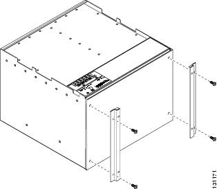
Figure 3 Installing the Left and Right Fan Filter Brackets

Install the Fan-Tray Air Filter in the External Brackets
Step 1
Although the filter will work if installed with either side facing up, Cisco recommends that you install it with the metal bracing facing up to preserve the surface of the filter. Figure 4 illustrates fan-tray air filter replacement when bottom brackets are used to install the filter.
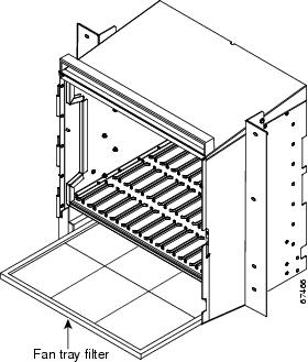
Figure 4 Installing the Fan-Tray Filter in the External Brackets

Install the Fan-Tray Air Filter Beneath the Fan-Tray Assembly
Step 1
If you are replacing the filter, remove the old filter.
Step 2
Note
Although the filter will work if installed with either side facing up, Cisco recommends that you install it with the metal bracing facing up to preserve the surface of the filter.
Figure 5 Installing the Fan-Tray Filter in the Shelf Assembly
Specifications
Power
Watts: 53
Amps: 1.1
BTU/hr: 180
Fan Speed
Slow: 2905 RPM
Medium: 3380 RPM
High: 3700 RPM
Shelf Acoustics
Slow fan speed: 55 dBA
Medium fan speed: 58.3 dBA
High fan speed: 60.3 dBA
Temperature Range
I-Temp compliant: -40 to +65 degrees Celsius
Related Documentation
•
•
•
Obtaining Documentation and Submitting a Service Request
For information on obtaining documentation, submitting a service request, and gathering additional information, see the monthly What's New in Cisco Product Documentation, which also lists all new and revised Cisco technical documentation, at:
http://www.cisco.com/en/US/docs/general/whatsnew/whatsnew.html
Subscribe to the What's New in Cisco Product Documentation as an RSS feed and set content to be delivered directly to your desktop using a reader application. The RSS feeds are a free service. Cisco currently supports RSS Version 2.0.
 Feedback
Contact Cisco
- Open a Support Case

- (Requires a Cisco Service Contract)