Connecting Cisco Grid Router WAN Interface Cards
Available Languages
Table Of Contents
Connecting Cisco Grid Router WAN Interface Cards
Cisco Grid Router WAN Interface Card LEDs
T1/E1 Channelized PRI GRWICs LEDs
Installing a Cisco Grid Router WAN Interface Card
Prerequisites for Connecting Cisco Grid Router WAN Interface Cards
Connecting Serial GRWICs to a Network
Connecting T1/E1 GRWICs to a Network
Obtaining Documentation, Obtaining Support, and Security Guidelines
Connecting Cisco Grid Router WAN Interface Cards
Revised: July 7, 2010, OL-23018-01Overview
This document describes Cisco grid router WAN interface cards (GRWICs) and how to connect them to a network. It contains the following sections:
•
Cisco Grid Router WAN Interface Card LEDs
•
Installing a Cisco Grid Router WAN Interface Card
•
Prerequisites for Connecting Cisco Grid Router WAN Interface Cards
•
Connecting Serial GRWICs to a Network
•
Connecting T1/E1 GRWICs to a Network
Supported Platforms
The GRWICs support the following Cisco 2000 Series Connected Grid routers:
•
Cisco CGR 2010 router
For appropriate regulatory warnings associated with this product, see Regulatory Compliance and Safety Information for Cisco Connected Grid Router 2000 Series Routers at:
http://www.cisco.com/en/US/docs/routers/access/2000/CGR2010/hardware/installation/guide/CGR2010_HIG.htmlFor an overview of Cisco GRWICs used for Cisco CGR 2010 routers, see Cisco Connected Grid Routers 2010 Hardware Installation Guide at:
http://www.cisco.com/en/US/docs/routers/access/2000/CGR2010/hardware/installation/guide/CGR2010_HIG.html
Note
Use Cisco Feature Navigator to find information about platform support and Cisco IOS software image support. Access Cisco Feature Navigator at http://www.cisco.com/go/fn. You must have an account on Cisco.com. If you do not have an account or have forgotten your username or password, click Cancel at the login dialog box and follow the instructions that appear.
8-Port Serial GRWICs
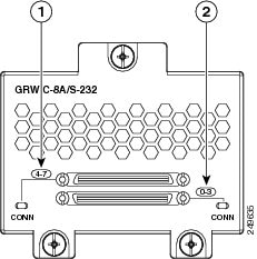
The 8-port serial GRWIC (RWIC-8A/S-232), shown in Figure 1, provides an EIA-323 serial interface to the Cisco GCR 2010 router. The serial GRWIC connectors each bundles signals for 4 ports.
Figure 1 8-Port Serial Grid Router WIC Front Panel

T1/E1 Channelized PRI GRWICs
The 1-port PRI T1/E1 GRWIC (GRWIC-1CE1T1-PRI) and 2-port PRI T1/E1 GRWIC (GRWIC-2CE1T1-PRI), shown in Figure 2, provides data only, channelized, clear channel T1/E1 connectivity to legacy equipment and sensors to an IP network.
Figure 2 2-Port Channelized T1/E1 PRI GRWIC

Cisco Grid Router WAN Interface Card LEDs
Figure 1 shows the serial GRWIC LEDs, and Figure 2 shows the T1/E1 GRWIC LEDs. Table 1 describes the serial GRWIC LED functions, and Table 2 shows the T1/E1 GRWIC LED functions.
8-Port Serial GRWICs LEDs
Figure 1 shows that each serial GRWIC has one LED, labeled CONN for each port group, which lights when the serial port is connected. When the port is in DTE mode, the CONN LED indicates that Data Send Ready (DSR), Data Carrier Detect (DCD), and Clear To Send (CTS) have been detected. When the port is in DCE mode, Data Terminal Ready (DTR) and Ready To Send (RTS) have been detected. There are two bi-color LEDs provided. One LED is for ports 0-3 and one LED is for ports 4-7 (see Figure 3). Table 1 describes the functions of the LEDs.
Figure 3 8-Port Serial GRWIC Bi-color LEDs

T1/E1 Channelized PRI GRWICs LEDs
The T1/E1 GRWIC has 2 LEDs for each port that indicate the functionality of the T1 or E1 connection. Figure 2 shows the front panel and LEDs. The LEDs are described in Table 2.

Note
CD/LP LEDs are bicolor LEDs with both green and yellow emitters.
Installing a Cisco Grid Router WAN Interface Card
This section describes how to install GRWICs in Cisco CGR 2010 routers.
The GRWIC installs into one of four slots on the cable side view of the router.

Note
You can install 4 single-wide GRWICs in the Cisco CGR 2010 router slots at any one time. Although double-wide GRWICs are not supported at this time, future versions of the Cisco CGR 2010 router will also support double-wide GRWIC configurations.
Follow these steps to install a GRWIC in a Cisco CGR 2010 router:
Step 1
Stand the GRWIC on end to install into the router slot. See Figure 4.
Figure 4 GRWIC Positioning to Install into the GCR 2010 Router

Step 2
Slide the GRWIC into the router slot. See Figure 5.
Figure 5 Proper Installation of a GRWIC

Step 3
Tighten the three captive screws on the front of the interface card.

CautionFor T1/E1 interfaces, shielded cables are required to meet EN55022, Cispr 22, and EN300-386 compliance.
Prerequisites for Connecting Cisco Grid Router WAN Interface Cards
Before connecting an GRWIC to the network, ensure that the GRWIC is installed in the router and you have the proper cables for connecting the GRWIC to the network.
Cables
After you install the GRWIC, use the appropriate serial or T1/E1 cable to connect the GRWIC's serial or T1/E1 port to one of the following types of equipment:
•
For serial, a synchronous modem, DSU or CSU, or other DCE, if connecting to a digital WAN line
•
For T1/E1, use a straight-through RJ-48C-to-RJ-48C cable to connect a T1/FT1 DSU/CSU HWIC to a network.
Connecting Serial GRWICs to a Network
To connect the serial GRWIC to the network, follow these steps:
Step 1
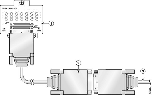
Connect the serial cable to the connector on the card faceplate. See Figure 6.
Figure 6 Connecting the Serial GRWIC Interface

Step 2
Connect the female end of the serial cable to the male end of the other serial connector for back-to-back connectivity. (See Figure 6.)
Step 3
Connect the other end of the cable to the DTE or DCE.
Connecting T1/E1 GRWICs to a Network
To connect the T1/E1 GRWIC to the network, follow these steps:
Step 1
Connect one end of the cable to the T1 port on the T1/E1 GRWIC (See Figure 7.)
Figure 7 Connecting the T1/E1 GRWIC to a T1 Wall Jack

Step 2
Connect the other end of the cable to the T1 wall jack, as shown in Figure 7.
Obtaining Documentation, Obtaining Support, and Security Guidelines
For information on obtaining documentation, obtaining support, providing documentation feedback, security guidelines, and also recommended aliases and general Cisco documents, see the monthly What's New in Cisco Product Documentation, which also lists all new and revised Cisco technical documentation, at:
http://www.cisco.com/en/US/docs/general/whatsnew/whatsnew.html
Cisco and the Cisco logo are trademarks or registered trademarks of Cisco and/or its affiliates in the U.S. and other countries. To view a list of Cisco trademarks, go to this URL: www.cisco.com/go/trademarks. Third-party trademarks mentioned are the property of their respective owners. The use of the word partner does not imply a partnership relationship between Cisco and any other company. (1110R)
© 2010 Cisco Systems, Inc. All rights reserved.
Contact Cisco
- Open a Support Case

- (Requires a Cisco Service Contract)
 Feedback