Gigabit Ethernet High-Speed WAN Interface Cards
Available Languages
Table Of Contents
Gigabit Ethernet High-Speed WAN Interface Cards
Cisco Gigabit Ethernet High-Speed WAN Interface Cards
Cisco Gigabit Ethernet High-Speed WAN Interface Card LEDs
Removing SFPs from Cisco Gigabit Ethernet High-Speed WAN Interface Cards
Cabling for Small Form-Factor Pluggable Modules
Connecting Cisco Gigabit Ethernet High-Speed WAN Interface Cards to the Network
Obtaining Documentation, Obtaining Support, and Security Guidelines
Gigabit Ethernet High-Speed WAN Interface Cards
Revised: 6/7/07, OL-12852-01Overview
This document describes Cisco Gigabit Ethernet high-speed WAN interface cards (HWICs) and how to connect a Cisco Gigabit Ethernet HWIC to the network, and contains the following sections:
•
Cisco Gigabit Ethernet High-Speed WAN Interface Cards
•
Cabling for Small Form-Factor Pluggable Modules
•
Connecting Cisco Gigabit Ethernet High-Speed WAN Interface Cards to the Network
•
Obtaining Documentation, Obtaining Support, and Security Guidelines
For an overview of Cisco interface cards used for Cisco access routers see the Cisco Interface Cards for Cisco Access Routers document.
Cisco Gigabit Ethernet High-Speed WAN Interface Cards
The Cisco Gigabit Ethernet high-speed WAN interface card (HWIC-1GE-SFP) is a high-speed interface card providing copper and optical Gigabit Ethernet connectivity for Cisco modular access routers.
The Cisco Gigabit Ethernet high-speed WAN interface card provides copper and optical Gigabit Ethernet connectivity through a small form-factor pluggable module (SFP), which is inserted into the interface card. (See the "Installing Small Form-Factor Pluggable Modules into Cisco Gigabit Ethernet High-Speed WAN Interface Cards" section.)
SFPs can be installed or removed without powering down the router and interface card.

CautionTo comply with the Telcordia GR-1089 NEBS standard for electromagnetic compatibility and safety, connect the Gigabit Ethernet high-speed WAN interface card (HWIC-1GE-SFP) only to intra-building or non-exposed wiring or cabling. The intrabuilding cable must be shielded and the shield must be grounded at both ends.

Note
The Cisco Gigabit Ethernet high-speed WAN interface card itself is not hot-swappable. Removal or insertion of the Cisco Gigabit Ethernet high-speed WAN interface card requires powering down the router.
The Cisco Gigabit Ethernet high-speed WAN interface card supports the SFPs shown in Table 34.

Note
Only Cisco-certified SFPs are supported on the Cisco Gigabit Ethernet high-speed WAN interface card.

Tip
When switching from one type of SFP to another, connection problems, including connection failure, may result. Use the show controller command at the Cisco IOS command-line interface (CLI) to determine whether you are using an SFP certified by Cisco.
Different SFPs have different cabling requirements; see the "Cabling for Small Form-Factor Pluggable Modules" section for more information on SFP cabling.
Laser Safety Guidelines
Optical SFPs use a small laser to generate the fiber-optic signal. Keep the optical transmit and receive ports covered whenever a cable is not connected to the port.
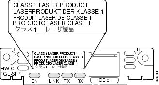
The interface card faceplate carries a Class 1 laser warning label. (See Figure 115.)
Figure 115 Class 1 Laser Warning Label


Warning
Because invisible laser radiation may be emitted from the aperture of the port when no fiber cable is connected, avoid exposure to laser radiation and do not stare into open apertures. Statement 125

Warning
Ultimate disposal of this product should be handled according to all national laws and regulations. Statement 1040
Cisco Gigabit Ethernet High-Speed WAN Interface Card LEDs
The Cisco Gigabit Ethernet high-speed WAN interface card uses LEDs to indicate card status and activity. (See Figure 116.)
Figure 116 Cisco Gigabit Ethernet High-Speed WAN Interface Card Faceplate (HWIC-1GE-SFP)

Installing Small Form-Factor Pluggable Modules into Cisco Gigabit Ethernet High-Speed WAN Interface Cards
Small form-factor pluggable modules (SFPs) are hot-swappable Ethernet interfaces that can be installed directly into the Cisco Gigabit Ethernet high-speed WAN interface card. See Table 34 for SFPs supported on the Cisco Gigabit Ethernet high-speed WAN interface card.
To install an SFP into the Cisco Gigabit Ethernet high-speed WAN interface card, perform the following steps:
Step 1
Install the interface card in the router. (See Chapter , "Installing Cisco Interface Cards in Cisco Access Routers.")

Warning
Because invisible laser radiation may be emitted from the aperture of the port when no fiber cable is connected, avoid exposure to laser radiation and do not stare into open apertures. Statement 125
Step 2
Slide the SFP into the housing on the interface card until it is locked into position. (See Figure 117.) The SFP is designed to prevent improper insertion.

Tip
If the SFP uses a bale-clasp latch (see Figure 117 and Figure 118), the bale-clasp handle should be on top of the SFP in the closed position for proper seating of the SFP module.
Figure 117 Installing an SFP on the Cisco Gigabit Ethernet High-Speed WAN Interface Card


CautionDo not remove the optical port plugs used on the SFP until you are ready to connect cabling to the interface card.

CautionTo comply with the Telcordia GR-1089 NEBS standard for electromagnetic compatibility and safety, connect the Gigabit Ethernet high-speed WAN interface card (HWIC-1GE-SFP) only to intra-building or non-exposed wiring or cabling. The intrabuilding cable must be shielded and the shield must be grounded at both ends.
Step 3
Connect the interface card to the network. (See the "Connecting Cisco Gigabit Ethernet High-Speed WAN Interface Cards to the Network" section.)
Removing Small Form-Factor Pluggable Modules from Cisco Gigabit Ethernet High-Speed WAN Interface Cards
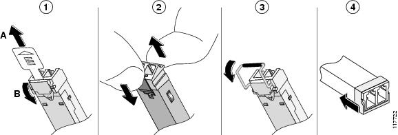
This section describes a generic removal procedure. Small form-factor pluggable modules (SFPs) use various latch designs (see Figure 118) to secure the module in the SFP port.

Note
Latch designs are not linked to SFP model or technology type; for information on the SFP technology type and model, see the label on the top or side of the SFP.
Removing SFPs from Cisco Gigabit Ethernet High-Speed WAN Interface Cards
To remove an SFP from a Cisco Gigabit Ethernet high-speed WAN interface card, perform the following steps:
Step 1
Disconnect all cables from the SFP.

Warning
Because invisible laser radiation may be emitted from the aperture of the port when no fiber cable is connected, avoid exposure to laser radiation and do not stare into open apertures. Statement 125

CautionThe latching mechanism used on many SFPs locks the SFP into place whenever cables are connected. Do not pull on the cabling in an attempt to remove the SFP.
Step 2
Disconnect the SFP latch (see Figure 118).
Figure 118 Disconnecting SFP Latch Mechanisms


Tip
Use a pen, screwdriver, or other small, straight tool to gently release the bale-clasp handle if you cannot reach it with your fingers.
Step 3
Grasp the SFP on both sides and remove it from the interface card.
Cabling for Small Form-Factor Pluggable Modules
Cisco Gigabit Ethernet high-speed WAN interface cards connect to the network through various supported small form-factor pluggable modules (SFPs). Cabling requirements vary by SFP. See the "Cabling for Small Form-Factor Pluggable Modules" section.
For information on cabling requirements for various small form-factor pluggable modules (SFPs) supported by the Cisco Gigabit Ethernet high-speed WAN interface card, see Table 35.
Table 35 Cabling Requirements for Gigabit Ethernet Small Form-Factor Pluggable Modules
1000BASE-T
GLC-T=
100 m
Category 5, 5e, 6
RJ-45
1000BASE-SX
GLC-SX-MM=
300 m
62.5/125 micrometer MMF1
LC connector
500 m
50/125 micrometer MMF
1000BASE-LX/LH
GLC-LH-SM=
550 m
50/125 micrometer or 62.5/125 micrometer MMF
LC connector
10 km
9/125 micrometer SMF2
1000BASE-ZX
GLC-ZX-SM=
80 km
9/125 micrometer SMF
LC connector
1000BASE-CWDM
CWDM-SFP-1470=
CWDM-SFP-1490=
CWDM-SFP-1510=
CWDM-SFP-1530=
CWDM-SFP-1550=
CWDM-SFP-1590=
CWDM-SFP-1610=100 km
9/125 micrometer SMF
LC connector
1 MMF = multimode fiber
2 SMF = singlemode fiber
Figure 119 LC Connector


Note
Coarse wavelength-division multiplexing (CWDM) SFP transceivers are color-coded based on wavelength: gray (1470), violet (1490), blue (1510), green (1530), yellow (1550), orange (1570), red (1590), and brown (1610).
Cisco Gigabit Ethernet high-speed WAN interface cards are designed for use in the following network design scenarios:
•
In metropolitan-area network (MAN) backbones for low-cost, high-speed, and long-distance connectivity
•
In multiprotocol WAN gateway routers for LANs
•
In same-building or same-campus wiring closets to achieve high-speed connectivity for high-demand network segments

Tip
For more information on possible network configurations using the Cisco Gigabit Ethernet high-speed WAN interface card, see Cisco product documentation.
Connecting Cisco Gigabit Ethernet High-Speed WAN Interface Cards to the Network
To connect the Cisco Gigabit Ethernet high-speed WAN interface card to the network, perform the following steps:
Step 1
Confirm successful insertion of the SFP.

Warning
Because invisible laser radiation may be emitted from the aperture of the port when no fiber cable is connected, avoid exposure to laser radiation and do not stare into open apertures. Statement 125
Step 2
Confirm that the router is powered down.
Step 3
Remove optical port plugs from the installed SFP.
Step 4
Use the appropriate cable (see Table 35) to connect to the installed SFP.

Note
For short distances or loopbacks, network installations using 1000BASE-CWDM and 1000BASE-ZX SFPs may require 15-dBm attenuators to avoid over-powering the connection. Calculate the power budget for the connection to determine which attenuator to use.
Step 5
For network installations that use 1000BASE-CWDM SFPs, connect the SFP to a Cisco CWDM optical add-drop multiplexing (OADM) interface card. (See Figure 120.) For information on the Cisco CWDM OADM, see the Installation Note for the Cisco CWDM Passive Optical System document.
Figure 120 Using a Cisco CWDM OADM Card to Connect the Cisco Gigabit Ethernet High-Speed WAN Interface Card to the Network

Step 6
Connect the other end of the appropriate cable (see Table 35) to your network.
Step 7
Continue router startup and configuration tasks.
Related Documentation
Related documentation is available on Cisco.com or on the Product Documentation DVD. For more information, see the "Obtaining Documentation, Obtaining Support, and Security Guidelines" section.
•
Cisco Gigabit Ethernet High-Speed WAN Interface Card for Cisco 2800 and 3800 Series Routers, data sheet
•
Cisco Gigabit Ethernet High-Speed WAN Interface Card, Q&A
•
Cisco Network Modules and Interface Cards Regulatory Compliance and Safety Information
•
"Configuring LAN Interfaces" chapter of the Cisco IOS Interface Configuration Guide, Release 12.2
Obtaining Documentation, Obtaining Support, and Security Guidelines
For information on obtaining documentation, obtaining support, providing documentation feedback, security guidelines, and also recommended aliases and general Cisco documents, see the monthly What's New in Cisco Product Documentation, which also lists all new and revised Cisco technical documentation, at:
http://www.cisco.com/en/US/docs/general/whatsnew/whatsnew.html

Any Internet Protocol (IP) addresses used in this document are not intended to be actual addresses. Any examples, command display output, and figures included in the document are shown for illustrative purposes only. Any use of actual IP addresses in illustrative content is unintentional and coincidental.
© 2007 Cisco Systems, Inc. All rights reserved.
Contact Cisco
- Open a Support Case

- (Requires a Cisco Service Contract)
 Feedback