Cisco CRS Carrier Routing System Packet-over-SONET/SDH Physical Layer Interface Module Installation Note
Available Languages
Table of Contents
Cisco IOS XR Software Release Requirements
Hardware Revision Requirements
Physical Layer Interface Modules
Before You Remove or Install a PLIM or an SFP Module
Preventing Electrostatic Discharge
Guidelines for Card Installation and Removal
How to Remove or Install a PLIM
How to Remove or Install an SFP Module
Removing a Bale-Clasp SFP Module
Installing a Bale-Clasp SFP Module
How to Remove or Install a PLIM Cable Management Bracket
Removing a PLIM Cable Management Bracket
Installing a PLIM Cable Management Bracket
POS/SDH and DPT Interface Specifications
OC-768c/STM-256c WDMPOS PLIM Interfaces
Removing and Installing Interface Cables
Verifying the Installation of a PLIM
Cisco Product Security Overview
Reporting Security Problems in Cisco Products
Obtaining Technical Assistance
Cisco Technical Support Website
Definitions of Service Request Severity
Obtaining Additional Publications and Information
Cisco CRS-1 Carrier Routing System Packet-over-SONET/SDH Physical Layer Interface Module Installation Note
Document Part Number: OL-6436-03
This document describes the Packet-over-SONET/SDH (POS) physical layer interface modules (PLIMs) used in the Cisco CRS-1 Carrier Routing System 16-slot and 8-slot line card chassis (LCC). It provides an overview of the different POS PLIMs and provides instructions on how to remove and install a PLIM and its associated components.
Contents
This document contains the following sections:
- Changes to This Document
- Important Information
- Physical Layer Interface Modules
- POS and POS/DPT PLIMs
- Before You Remove or Install a PLIM or an SFP Module
- How to Remove or Install a PLIM
- How to Remove or Install an SFP Module
- Cleaning Optics
- How to Remove or Install a PLIM Cable Management Bracket
- Cabling and Specifications
- Verifying the Installation of a PLIM
- Obtaining Documentation
- Documentation Feedback
- Cisco Product Security Overview
- Obtaining Technical Assistance
- Obtaining Additional Publications and Information
Changes to This Document
Table 1 lists the technical changes made to this document since it was first printed.
- Information about the 1-port OC-768c/STM-256c WDMPOS PLIM was added to the “OC-768c/STM-256c WDMPOS PLIM”.
- Cable management information was added to the “How to Remove or Install a PLIM Cable Management Bracket” section.
- Optics information for the 1-port OC-768c/STM-256c WDMPOS PLIM was added to the “OC-768c/STM-256c WDMPOS PLIM Interfaces”.
- The “Changes to This Document” section was added.
- Part numbers and related documentation were reorganized into the “Important Information” section.
- Cable management bracket information was removed from the “Guidelines for Card Installation and Removal” section because that procedure is described in installation guides.
- Optics information for the POS PLIMs was added to the “Cabling and Specifications” section.
- DPT information was added, including a DPT cabling example, to the “PLIM Interface Cables” section.
- Figure 2, Figure 4, Figure 5, and Figure 6 were revised to show more details.
- LED information was reorganized in one location: “POS and DPT LED Descriptions” section.
- The “Reporting Security Problems in Cisco Products” section was added.
- The term “slot” was changed to “port” in regard to the SFP receptacle.
- References to 10-GE PLIM were removed.
Important Information
This section contains the following sections:
- Product Numbers
- Router Hardware Installation
- Cisco IOS XR Software Release Requirements
- Hardware Revision Requirements
- Related Documentation
Product Numbers
Table 2 lists the Cisco product numbers of the products to which this publication applies.
Table 2 PLIM Descriptions and Software and Hardware Compatibility
1-port OC-768/STM-256c (C-band) DWDM PLIM [full 80 channels]
Operates within the 50GHz spectrum1-port OC-768 DPSK+ (C-band) DWDM PLIM [even channels only]
Operates within the 50GHz spectrum1-port OC768 (C-band) DPSK+ DWDM PLIM (Offset TDC) [odd channels only]
Operates within the 50GHz spectrum4-port OC-192c/STM-64c POS/DPT PLIM, with intermediate-reach optics
4-port OC-192c/STM-64c POS/DPT PLIM, with short-reach optics
4-port OC-192c/STM-64c POS/DPT PLIM, with very-short-reach optics
16-port OC-48c/STM-16c POS/DPT PLIM, with small form-factor pluggable (SFP) optics modules:
PLIM impedance carrier1
1.The PLIM impedance carrier is required for EMI compliance and cooling.
Router Hardware Installation
For hardware installation and configuration information for the Cisco CRS-1 router, see router hardware installation documents in the “Related Documentation” section . These documents include information on the router switch fabric and how it affects operation of the PLIM. The also include PLIM slot locations and other requirements.
The PLIMs described in this document are supported on both the 8-slot and 16-slot Cisco CRS-1 router line card chassis.
Cisco IOS XR Software Release Requirements
Table 2 lists the Cisco IOS XR releases that are compatible with POS PLIMs.
For software configuration information, see the Cisco IOS XR software configuration and command reference publications for the installed Cisco IOS XR release at the following URL:
http://www.cisco.com/en/US/products/ps5763/products_installation_and_configuration_guides_list.
htmlSee the Cisco IOS XR software release notes for additional software release information at the following URL:
http://www.cisco.com/en/US/products/ps5763/prod_release_notes_list.html
Hardware Revision Requirements
To ensure compatibility with the software, your POS PLIM should have a specific hardware revision number. This number is printed on a label affixed to the component side of the PLIM. The hardware revision number can also be displayed using the show diag command. Minimum revision numbers are listed in Table 2.
Related Documentation
For complete planning, installation, and configuration information, see the documents for your chassis type (16-slot or 8-slot) listed in this section. Cisco CRS-1 router product documentation is available on line at the following URL:
http://www.cisco.com/univercd/cc/td/doc/product/core/crs/index.htm
Hardware Documents
These hardware documents are part of the Cisco CRS-1 router line card chassis documentation set:
- Cisco CRS-1 Carrier Routing System Hardware Documentation Guide (ships with product)
- Cisco CRS-1 Carrier Routing System 16-Slot Line Card Chassis Site Planning Guide
- Cisco CRS-1 Carrier Routing System 8-Slot Line Card Chassis Site Planning Guide
- Cisco CRS-1 Carrier Routing System 16-Slot Line Card Chassis System Description
- Cisco CRS-1 Carrier Routing System 8-Slot Line Card Chassis System Description
- Cisco CRS-1 Carrier Routing System 16-Slot Line Card Chassis Unpacking, Moving, and Securing Guide (attached to the crate)
- Cisco CRS-1 Carrier Routing System 8-Slot Line Card Chassis Unpacking, Moving, and Securing Guide (attached to the crate)
- Cisco CRS-1 Carrier Routing System 16-Slot Line Card Chassis Installation Guide
- Cisco CRS-1 Carrier Routing System 8-Slot Line Card Chassis Installation Guide
- Regulatory Compliance and Safety Information for the Cisco CRS-1 Carrier Routing System (ships with product)
Software Documents
For POS and SRP configuration information, see Cisco IOS XR Interface and Hardware Component Configuration Guide and Cisco IOS XR Interface and Hardware Component Command Reference .
For a complete listing of software documentation available for the Cisco CRS-1 router, see About Cisco IOS XR Software Documentation for your release, available on line at the following URL:
http://www.cisco.com/en/US/products/ps5763/products_documentation_roadmaps_list.html
Physical Layer Interface Modules
A physical layer interface module (PLIM) provides the packet interfaces for the routing system. Optic modules on the PLIM contain ports to which fiber-optic cables are connected. User data is received and transmitted through the PLIM ports and converted between the optical signals (used in the network) and the electrical signals (used by Cisco CRS-1 router components).
Each PLIM is paired with a modular services card (MSC) through the chassis midplane. The MSC provides Layer 3 services for the user data, and the PLIM provides Layer 1 and Layer 2 services. An MSC can be paired with different PLIMs to provide a variety of packet interfaces and port densities (for example, OC-192c/STM-64c POS and 10-Gigabit Ethernet).
MSCs and PLIMs are installed on opposite sides of the line card chassis and mate through the chassis midplane. Each MSC and PLIM pair is installed in corresponding chassis slots in the chassis (on opposite sides of the chassis). The chassis midplane enables you to remove and replace an MSC without disconnecting the user cables on the PLIM.
The Cisco CRS-1 router supports the following number of PLIMs for each chassis type. You can mix and match PLIM types in the chassis.
For additional information about the operation of MSCs and PLIMs, see Cisco CRS-1 Carrier Routing System Line Card Chassis System Description for the 16-slot or 8-slot chassis.
POS and POS/DPT PLIMs
The Cisco CRS-1 router supports the following types of POS and POS/DPT PLIMs:
- OC-768c/STM-256c POS PLIM: available with short-reach (SR) optics.
- OC-768c/STM-256c WDMPOS PLIM: available with tunable DWDM optics.
- OC-192c/STM-64c POS/DPT PLIM: available with long-reach (LR), intermediate-reach (IR), short-reach (SR), and very-short-reach (VSR) optics.
- OC-48c/STM-16c POS/DPT PLIM; available with small form-factor pluggable (SFP) optics modules for long-reach (LR) and short-reach (SR) optics.
The POS PLIMs all share the following features:
- SONET/SDH path, line, and section processing
- Point-to-Point Protocol (PPP) and high-level data link control (HDLC) encapsulation; Spatial Reuse Protocol (SRP) version 2 encapsulation for OC-192c/STM-64c POS/DPT PLIM only
- Online insertion and removal (OIR)
- Local (internal) and loop-timed (network-recovered) clocks; Stratum-3 accuracy
- Network management: Cisco IOS XR CLI, SNMP, XML, and Craft Works Interface (CWI)
- Alarm detection (with user-configurable thresholds) and performance monitoring
- Payload scrambling and pointer processing
- Compliance with network and industry standards
For additional features and specifications, see the data sheets at the following URL:
http://www.cisco.com/en/US/products/ps5763/products_data_sheets_list.html
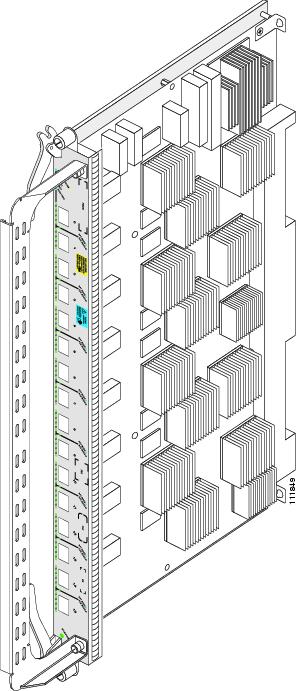
Figure 1 shows an illustration of a PLIM. The OC-48c/STM-16c POS/DPT PLIM is shown; other PLIMs are similar.
Figure 1 16-Port OC-48c/STM-16c POS/DPT PLIM
The following sections describe the POS and POS/DPT PLIMs currently available for the Cisco CRS-1 router:
- OC-768c/STM-256c POS PLIM
- OC-768c/STM-256c WDMPOS PLIM
- OC-192c/STM-64c POS/DPT PLIM
- OC-48c/STM-16c POS/DPT PLIM
- PLIM Impedance Carrier
OC-768c/STM-256c POS PLIM
The 1-port OC-768 PLIM provides a single interface of 40 gigabits per second (Gbps), which is the OC-768c/STM-256c line rate. The PLIM performs Layer 1 and Layer 2 processing for a single OC-768c/STM-256c data stream by removing and adding the proper header information as data packets enter and exit the PLIM. The PLIM passes the MSC a single 40-Gbps data packet stream.
The 1-port OC-768 PLIM is thermally-sensitive. See Thermal Restrictions.
The OC-768 PLIM is a Class 1 laser product that operates in POS mode only. The PLIM contains:
- Optics module—Provides receive (RX) and transmit (TX) optic interfaces that comply with ITU Recommendation G.693. The module provides short-reach (SR) optics with SC fiber-optic interfaces.
- Framer—Provides processing and termination for SONET/SDH section, line, and path layers, including alarm processing and automatic protection switching (APS) support.
- Physical interface controller—Provides data packet buffering and Layer 2 processing, including processing for VLANs and back-pressure signals from the MSC.
- Additional components—Include power and clocking components, voltage and temperature sensors, and an identification EEPROM that stores initial configuration and PLIM hardware information.
The Cisco IOS XR software also provides diagnostic functions for the PLIM. See “Related Documentation” for more information.
- Three LEDs for the optics port (ACTIVE, CARRIER, and RX PKT)
- STATUS LED to indicate PLIM operation.
- The following physical characteristics:
Figure 2 shows the front panel of the OC-768 PLIM.
Figure 2 1-Port OC-768c/STM-256c POS PLIM Front Panel


Note The following restrictions apply only to the legacy 16-slot chassis.
Cisco CRS thermally-sensitive PLIMs are subject to slot placement restrictions on the legacy 16-slot chassis. The following error message appears if these restrictions are not followed:
PLATFORM-SHELFMGRV2-4-AVOID_THERMALLY_SENSITIVE_PLIM_IN_UPPER_SLOT
The thermally-sensitive PLIM limitation is due to the possibility of some components exceeding their rated temperature tolerance when the system is run at 50C at elevations of 1800 meters or higher. If the high temperature condition occurs, the environmental monitoring software will shut down the thermally-sensitive PLIM when its temperature reaches configured thresholds. Therefore, this restriction applies only to routers operating at these high elevations and may be ignored otherwise.
OC-768c/STM-256c WDMPOS PLIM
The Cisco CRS-1 1-port OC-768c/STM-256c tunable WDMPOS PLIM supports IP over dense wavelength-division multiplexing (DWDM) at 40 gigabits per second (Gbps), which is the OC-768c/STM-256c line rate. The OC-768c/STM-256c WDMPOS PLIM connects directly into any DWDM network and provides up to 40 Gbps of data throughput across existing 10-Gbps DWDM systems. The PLIM is completely tunable across the C band with 50-GHz spacing and supports high-gain Enhanced Forward Error Correction (EFEC), extending reach up to 1000 kilometers (km) without requiring signal regeneration.
The Cisco CRS-1 1-port OC-768c/STM-256c tunable WDMPOS PLIM is a high-powered PLIM. See Power Management Restrictions. It is also a thermally-restricted PLIM. See Thermal Restrictions.
The PLIM is a Class 1 laser product that contains:
- Optics port—Provides receive (RX) and transmit (TX) optic interfaces with Lucent connector (LC) fiber-optic interfaces.
- G.709/FEC Framer—Provides ITU G.709 framing for DWDM alarm and performance monitoring, and enhanced forward error correction to extend the optical reach to 1000 km without requiring electrical regeneration.
- Framer—Provides processing and termination for SONET/SDH section, line, and path layers, including alarm processing and automatic protection switching (APS) support.
- Physical interface controller—Provides data packet buffering and Layer 2 processing, including processing for VLANs and back-pressure signals from the MSC.
- Additional components—Include power and clocking components, voltage and temperature sensors, and an identification EEPROM that stores initial configuration and PLIM hardware information.
The Cisco IOS XR software also provides diagnostic functions for the PLIM. See “Related Documentation” for more information.
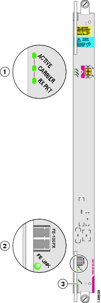
- Three LEDs for the optics port (ACTIVE, CARRIER, and RX PKT).
- Fast Ethernet (FE) port and FE LINK LED to indicate the FE port status. The FE port is implemented with SFP optics and supports connectivity to external “Dynamic Optical Modules” that may be used in the future.
- STATUS LED to indicate PLIM operation.
- The following physical characteristics:
Figure 2 shows the front panel of the OC-768c/STM-256c WDMPOS PLIM.
Figure 3 1-Port OC-768c/STM-256c WDMPOS PLIM Front Panel

Note The following restrictions apply only to the legacy 16-slot chassis.
Cisco CRS high-powered PLIMs are subject to slot placement restrictions on the legacy 16-slot chassis. The following error message appears if these restrictions are not followed:
PLATFORM-SHELFMGRV2-4-HIGH_POWERED_PLIM_NOT_POWERED_ON_IN_LOWER_BAY
The following PLIMs are high-powered PLIMs:
- CRS-CGSE-PLIM—Cisco CRS Carrier Grade Services Engine (CGSE) PLIM
- 1OC768-DPSK/C-O—Cisco CRS-1 1xOC768 (C-band) DPSK+ DWDM PLIM (Offset TDC)
- 6-10GE-WLO-FLEX—Cisco CRS Flexible PLIM
- 4-40GE-L/OTN—Cisco CRS 4-Port 40 GE LAN/OTN Interface Module
The rules for placement of high-powered PLIMs are:
1.
A FLEX PLIM (6-10GE-WLO-FLEX) in the lower shelf cannot be placed under a CGSE PLIM directly above in the upper shelf.
2.
High-powered PLIMs may only be placed in lower slots if a high-powered PLIM is in the slot directly above or if the slot above is empty.

Note The following restrictions apply only to the legacy 16-slot chassis.
Cisco CRS thermally-sensitive PLIMs are subject to slot placement restrictions on the legacy 16-slot chassis. The following error message appears if these restrictions are not followed:
PLATFORM-SHELFMGRV2-4-AVOID_THERMALLY_SENSITIVE_PLIM_IN_UPPER_SLOT
The thermally-sensitive PLIM limitation is due to the possibility of some components exceeding their rated temperature tolerance when the system is run at 50C at elevations of 1800 meters or higher. If the high temperature condition occurs, the environmental monitoring software will shut down the thermally-sensitive PLIM when its temperature reaches configured thresholds. Therefore, this restriction applies only to routers operating at these high elevations and may be ignored otherwise.
OC-192c/STM-64c POS/DPT PLIM
The 4-port OC-192c/STM-64c POS/DPT PLIM contains four ports that can be software configured to operate in Packet-over-SONET/SDH (POS) or Dynamic Packet Transport (DPT) mode. The PLIM performs Layer 1 and Layer 2 processing for four OC-192/STM-64 data streams by removing and adding the proper header information as data packets enter and exit the PLIM. The PLIM feeds the MSC a single 40-Gbps data packet stream.
The VSR version of the PLIM is a Class 1M laser product. All other versions (LR, IR, and SR) are Class 1 laser products.
The 4-port OC-192c/STM-64c POS/DPT PLIM contains:
- Optics modules—Provide receive (RX) and transmit (TX) optic interfaces that comply with GR-253-CORE. The PLIM supports the following types of optics (see Table 2 for product IDs):
–
Long-reach (LR) optics with SC fiber-optic interfaces
–
Intermediate-reach (IR) optics with SC fiber-optic interfaces
–
Short-reach (SR) optics with SC fiber-optic interfaces
–
Very-short-reach (VSR) optics with standard MTP (MPO) multifiber optic interfaces
- Framers—Provide processing and termination for SONET section, line, and path layers, including alarm processing and automatic protection switching (APS) support. The framer supports both packet and cell processing for a multiservice operating mode.
- Physical interface controller—Provides data packet buffering and Layer 2 processing and multiplexing and demultiplexing on the four OC-192/STM-64 data streams. The controller provides processing for back-pressure signals from the MSC and does not perform Layer 2 processing specific to Spatial Reuse Protocol (SRP).
- DPT or transparent mode components—Provide the MAC layer function for the SRP used in DPT mode. When the PLIM is in POS mode, these components operate in the transparent mode, or as though they are not present; for example, the SRP hardware component is not needed or used in POS mode.
- Additional components—Provide power, clocking, voltage and temperature sensing, and an identification EEPROM that stores initial configuration information and details about the PLIM type and hardware revision.
The Cisco IOS XR software also provides loopback and diagnostic functions for the PLIM. See Cisco IOS XR Interface and Hardware Component Configuration Guide located at the following URL:
http://www.cisco.com/en/US/products/ps5763/products_installation_and_configuration_guides_list.
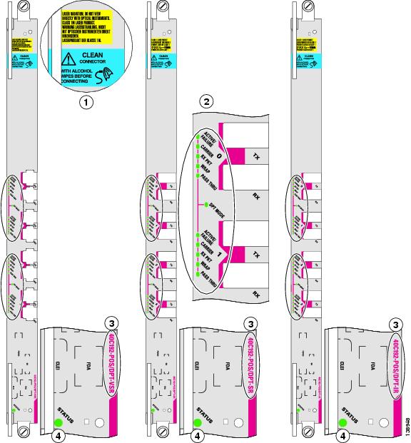
htmlFigure 4 shows the front panels of the OC-192c/STM-64c POS/DPT PLIMs.

Warning Class 1 Laser Product Statement 113
Figure 4 4-Port OC-192c/STM-64c POS/DPT PLIM Front Panels (VSR, SR, and IR Shown)
The 4-port OC-192c/STM-64c POS/DPT PLIM has:
- Four ports (0, 1, 2, and 3) with TX and RX jacks for each port. The VSR version of the PLIM provides standard MTP (MPO) multifiber optic interfaces. All other PLIMs (LR, IR, and SR) have SC fiber-optic interfaces.
- STATUS LED to indicate PLIM operation.
- Five LEDs for each port (ACTIVE/FAILURE, CARRIER, RX PKT, WRAP, and PASS THRU)
- Two DPT MODE LEDs corresponding to each pair of ports (0 and 1, 2 and 3)
- The following physical characteristics:
OC-48c/STM-16c POS/DPT PLIM
The 16-port OC-48c/STM-16c POS/DPT PLIM contains 16 OC-48/STM-16 2.5-G optic interfaces that can be software configured to operate in Packet-over-SONET/SDH (POS) or Dynamic Packet Transport (DPT) mode. The PLIM performs Layer 1 and Layer 2 processing for 16 OC-48/STM-16 data streams by removing and adding the proper header information as data packets enter and exit the PLIM. The PLIM feeds the MSC a single 40-Gbps data packet stream.

Note The OC-48c/STM-16c POS/DPT PLIM supports only POS.
The 16-port OC-48c/STM-16c POS/DPT PLIM consists of:
- Optics modules—Provide the receive (RX) and transmit (TX) optic interfaces for each of the 16 ports. The PLIM uses small form-factor pluggable (SFP) optic modules that can be removed and replaced while the PLIM is powered up. The SFPs provide short-reach (SR) and long-reach (LR2) optics with LC fiber-optic interfaces.
- Framers—Provide processing and termination for SONET section, line, and path layers, including alarm processing and APS support and management. The framer supports both packet and cell processing for a multiservice operating mode.
- DPT or transparent mode components—Provide the MAC layer function for the Spatial Reuse Protocol used in DPT mode. When the PLIM operates in the POS mode (the default), these components operate in the transparent mode (as though they are not there).
- Physical interface controller—Provides data packet buffering and Layer 2 processing and multiplexing and demultiplexing of the 16 OC-48/STM-16 data streams. The controller also provides processing for VLANs and back-pressure signals from the MSC.
- Additional components—Provide power, clocking, voltage and temperature sensing, and an identification EEPROM that stores initial configuration information and details about the PLIM type and hardware revision.
The Cisco IOS XR software also provides loopback and diagnostic functions for the PLIM. See Cisco IOS XR Interface and Hardware Component Configuration Guide located at the following URL:
http://www.cisco.com/en/US/products/ps5763/products_installation_and_configuration_guides_list.
htmlFigure 5 shows the front panel of the OC-48c/STM-16c POS/DPT PLIM.

Warning Class 1 Laser Product Statement 113
Figure 5 16-Port OC-48c/STM-16c POS/DPT PLIM Front Panel

The 16-port OC-48c/STM-16c POS/DPT PLIM has:
- Sixteen ports for SFP optic modules, which provide SR or LR optics with LC fiber-optic interfaces.
- STATUS LED to indicate PLIM operation
- Five LEDs for each port (ACTIVE/FAILURE, CARRIER, RX PKT, WRAP, and PASS THRU)
- Eight DPT MODE LEDs corresponding to each pair of ports (0 and 1, 2 and 3, and so on)
- The following physical characteristics:
PLIM Impedance Carrier
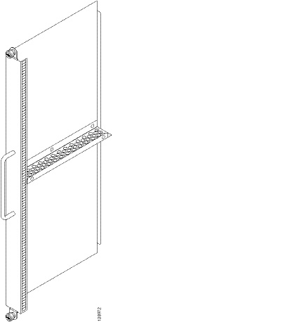
A PLIM impedance carrier must be installed in each empty PLIM slot in the Cisco CRS-1 chassis (see Figure 6). The impedance carrier preserves the integrity of the chassis and is required for EMI compliance and proper cooling in the chassis.
Figure 6 PLIM Impedance Carrier
Before You Remove or Install a PLIM or an SFP Module
Review the following sections carefully before you remove or install a PLIM or an SFP module:
Safety Guidelines
Before you perform any procedure in this document, review the safety guidelines in this section to avoid injuring yourself or damaging the equipment.
The following guidelines are for your safety and to protect equipment. The guidelines do not include all hazards. Be alert.

Note Review the safety warnings listed in Regulatory Compliance and Safety Information for the Cisco CRS-1 Carrier Routing System before installing, configuring, or troubleshooting any installed card.
- Never attempt to lift an object that might be too heavy for you to lift by yourself.
- Keep the work area clear and dust free during and after installation. Do not allow dirt or debris to enter into any laser-based components.
- Keep tools and router components away from walk areas.
- Do not wear loose clothing, jewelry, and other items that could get caught in the router while working with OIMs, SFCs, and their associated components.
- Use Cisco equipment in accordance with its specifications and product-usage instructions.
- Do not work alone if potentially hazardous conditions exist.
- Make sure your installation follows national and local electrical codes: in the United States, National Fire Protection Association (NFPA) 70, United States National Electrical Code; in Canada, Canadian Electrical Code, part I, CSA C22.1; in other countries, International Electrotechnical Commission (IEC) 60364, part 1 through part 7.
- Connect only a DC power source that follows the safety extra-low voltage (SELV) requirements in UL/CSA/IEC/EN 60950-1 and AS/NZS 60590 to the FCC DC-input power system.
- Make sure that you have a readily accessible two-poled disconnect device incorporated in the fixed wiring of an LCC configured with the DC-input power system.
- The LCC requires short-circuit (overcurrent) protection to be provided as part of the building installation.
Preventing Electrostatic Discharge
Electrostatic discharge (ESD) damage, which can occur when electronic cards or components are improperly handled, results in complete or intermittent failures. We recommend that you use an ESD-preventive strap whenever you handle network equipment or components.
Following are guidelines for preventing ESD damage:
- Always use an ESD-preventive wrist or ankle strap, and ensure that it makes good skin contact. Connect the equipment end of the connection cord to an ESD connection socket on the router or a bare metal surface on the chassis.
- Handle a card by its ejector levers, when applicable, or metal carrier only; avoid touching the board or connector pins.
- Place a removed card component side up on an antistatic surface or in a static-shielding bag. If you plan to return the component to the factory, immediately place it in a static-shielding bag.
- Avoid contact between the card and clothing. The wrist strap protects the board only from ESD voltage on the body; ESD voltage on clothing can still cause damage.
Guidelines for Card Installation and Removal
Guidelines for card installation and removal include the following:
- Online insertion and removal (OIR) is supported, enabling you to remove and install cards while the router is running. OIR is seamless to users on the network, maintains all routing information, and ensures session preservation. Notifying the software or resetting the power is not required. However, you have the option of using the shutdown command before removing a card.

Note For PLIMs with DPT interfaces, we recommend that you use the srp ips request forced-switch command to minimize data loss. See Cisco IOS XR Interface and Hardware Component Configuration Guide for details.
- Each PLIM and its corresponding MSC function as a pair. If either card is removed, the other card is essentially powered down (although the router can still identify and inventory the cards).
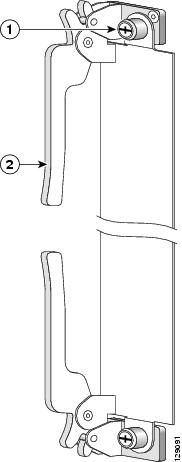
- PLIMs in the line card chassis are attached to the chassis by way of a pair of ejector levers and captive screws. The two ejector levers are used to release the PLIM from its midplane connector. The ejector levers and captive screws are located on the upper and lower ends of the faceplate of the card (see Figure 7).
Figure 7 Ejector Levers and Captive Screws

Caution When you remove a PLIM, always use the ejector levers to ensure that the connector pins disconnect from the midplane in the sequence expected by the router.
The router can indicate a hardware failure if you do not follow proper procedures. Remove or install only one card at a time. Wait at least 15 seconds before removing or installing another card.
How to Remove or Install a PLIM
A PLIM provides the data interfaces for the routing system and mates with its associated MSC through the chassis midplane.
This section contains the following procedures:
Steps
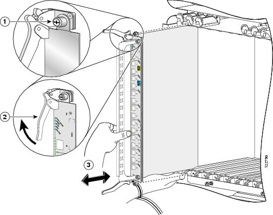
To remove a PLIM, see Figure 8 and follow these steps (the 16-port OC-48c/STM-16c POS/DPT PLIM is shown in the illustration, but the installation procedure is similar for all PLIMs).
Step 1
Attach the ESD-preventive wrist strap and follow its instructions for use.
Step 2
Identify the card to be replaced, and unplug the interface cables connected to the card. Be sure to note the current connections of the cables to the ports on the PLIM.
Warning Because invisible radiation may be emitted from the aperture of the port when no fiber cable is connected, avoid exposure to radiation and do not stare into open apertures. Statement 125


Note You can also keep the dust caps or covers on the laser optical bores to avoid radiation exposure.
Step 3
(OC-48c/STM-16c POS/DPT PLIMs only) Remove the SFP modules from the card and set them aside. See the “How to Remove or Install an SFP Module” section.
Step 4
Loosen the two captive screws holding the card in place.
Step 5
Grasp the two card ejector levers and simultaneously pivot both ejector levers 90 degrees (70 degrees for a newer PLIM) away from the front edge of the card carrier to unseat the card from the backplane.
Step 6
Grasp the cable management bracket and gently pull the PLIM halfway from the slot.
Step 7
Slide the card from the slot, using one hand under the PLIM to support and guide it. Avoid touching the PLIM printed circuit board, components, or any connector pins. Do not lift cards by the cable management bracket; lift them from the bottom, using the cable management bracket only as an aid for balance.
Step 8
Place the PLIM directly into an antistatic sack or other ESD-preventive container.
Step 9
Insert another PLIM or an impedance carrier into the empty card slot.
Figure 8 Removing or Installing a PLIM
Installing a PLIM
This section describes how to install a PLIM in the line card chassis. You can install a PLIM in any slot not occupied by a route processor (RP) card (or a fan controller card, 16-slot chassis only). If you install a new MSC or PLIM, you must first remove the impedance carrier card from the available slot.

Steps
To install a PLIM, see Figure 8 and follow these steps:
Step 1
Attach the ESD-preventive wrist strap and follow its instructions for use.
Step 2
Remove the PLIM from its antistatic packaging.
Step 3
Remove the PLIM impedance carrier from the slot you need to fill and set it aside.

Note Remove only one impedance carrier and install one PLIM at a time. Be sure to verify that each PLIM is fully installed and secured before installing another card.
Step 4
Grasp the cable management bracket with one hand and place your other hand under the carrier to support and guide the card into the correct slot. Slide the card halfway into the correct slot. Avoid touching the card circuitry or any connectors.
Step 5
Pivot both card ejector levers so that the openings on the card ejector cams at the top and bottom of the card pass over the tabs on each side of the card cage slot.

Caution Verify that the openings on the card ejector cams pass over the tabs; otherwise, one or both ejector levers might bind when you attempt to close the ejector levers, thereby damaging or breaking one or both ejector levers.
Step 6
Continue sliding the card into the card cage slot until the openings on the card ejector cams engage the tabs on each side of the card cage slot.

Note Guide pins exist that make initial contact with the backplane connector as you slide a card into its slot. After the guide pins make contact, continue pushing on the card carrier until the card ejector levers begin pivoting forward toward the handle in the card carrier.
Step 7
To seat the card in the midplane connector, grasp both card ejector levers and pivot them inward toward the handle in the card carrier until they are flush against the front edge of the card carrier.
Step 8
Engage both captive screws on the PLIM, and then tighten the screws.

Caution Be sure to engage both captive screws on the PLIM before you begin to tighten the screws; otherwise, the PLIM might not seat properly.

Caution To ensure adequate space for additional PLIMs, always tighten the captive installation screws on each newly installed PLIM before you insert another PLIM. These screws also prevent accidental removal and provide proper grounding and EMI shielding for the system.
Step 9
(OC-48c/STM-16c POS/DPT PLIMs only) Install the SFP modules.
Step 10
Install the interface cables. We recommend that you clean the fiber-optic connections before attaching the cables. See the URL http://www.cisco.com/warp/public/127/cleanfiber2.html for cleaning instructions.
Step 11
If this PLIM is new, configure it for operation. For instructions, see Cisco IOS XR Interface and Hardware Component Configuration Guide and the Cisco IOS XR Interface and Hardware Component Command Reference , available at the following URL:
http://www.cisco.com/univercd/cc/td/doc/product/software/iosxr/index.htm

Warning Because invisible radiation may be emitted from the aperture of the port when no fiber cable is connected, avoid exposure to radiation and do not stare into open apertures. Statement 125

Note You can also keep the dust caps or covers on the laser optical bores to avoid radiation exposure.
How to Remove or Install an SFP Module
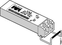
A small form-factor pluggable (SFP) module provides the optics ports for some types of PLIMs. An SFP module is installed into a port on the PLIM. The SFP module has a bale-clasp latch that you use to install or remove the module (see Figure 9).
Figure 9 Bale-Clasp SFP Module

Caution Protect the SFP module by inserting a clean dust cover into the module after you remove the fiber cable. Be sure to clean the optic surfaces of the fiber cable before you plug the cable into another module. Avoid getting dust and other contaminants in the optical port of the SFP module. The optics do not work correctly when obstructed with dust.

Note Only the 16-port OC-48c/STM-16c POS/DPT PLIM uses SFP modules.
Steps
To remove a bale-clasp SFP module from a PLIM, follow these steps:
Step 1
Attach the ESD-preventive wrist strap and follow its instructions for use.

Warning Because invisible radiation may be emitted from the aperture of the port when no fiber cable is connected, avoid exposure to radiation and do not stare into open apertures. Statement 125
Step 2
Disconnect and remove all interface cables from the ports. Be sure to note the current connections of the cables to the ports on the PLIM.

Note You can also keep the dust caps or covers on the laser optical bores to avoid radiation exposure.
Step 3
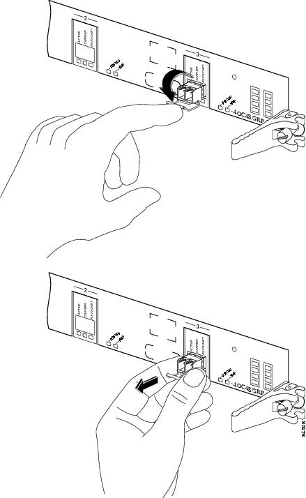
Open the bale-clasp on the module with your index finger in a downward direction, as shown in Figure 10. If the bale-clasp is obstructed and you cannot use your index finger to open it, use a small screwdriver or other long, narrow instrument to open the bale clasp.
Step 4
Grasp the module between your thumb and index finger and carefully remove it from the port, as shown in the following figure.

Note Be careful to hold the module in such a way so as to not damage the bale clasp.
Figure 10 Removing a Bale-Clasp SFP Module
Step 5
Place the removed module on an antistatic mat, or immediately place it in a static-shielding bag if you plan to return it to the factory.
Step 6
Protect the PLIM by inserting clean SFP module cage covers into the optical module cage when no module is installed.
Required Tools and Equipment
You need the following tool and part to install a bale-clasp SFP module:
Steps
To install a bale-clasp SFP module into a PLIM, follow these steps:
Step 1
Attach the ESD-preventive wrist strap and follow its instructions for use.
Step 2
Close the bale-clasp before inserting the module.
Step 3
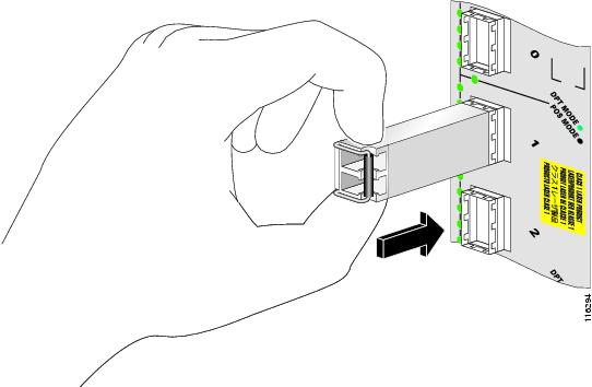
Align the module with the port and slide it into the port (see Figure 11).

Note Be careful to hold the module in such a way so as to not damage the bale clasp.
Figure 11 Installing a Bale-Clasp SFP Module into a Port
Cleaning Optics
It is important to inspect and clean fiber-optic components before making a fiber-optic connection (for example, plugging a fiber-optic connector into a fiber-optic receptacle). Any contamination in the fiber connection can cause the optic component or the whole system to fail. Even microscopic dust particles, oil from human hands, film residues (condensed from vapors in the air), and powdery coatings (left after water or other solvents evaporate) can cause a variety of problems for optical connections.

Caution With the high-powered lasers now in use, any contaminant can be burned into the fiber end face if it blocks the core while the laser is turned on. This burning may damage the optical surface enough that it cannot be cleaned.
See the following URL for instructions on how to clean fiber-optic components:
http://www.cisco.com/warp/public/127/cleanfiber2.html
Always follow the fiber-optic cleaning procedures carefully. The goal is to eliminate any dust or contamination and provide a clean environment for the fiber-optic connection. Inspection, cleaning, and reinspection are critical steps that must be performed before making any fiber-optic connection.
How to Remove or Install a PLIM Cable Management Bracket
Cisco CRS-1 chassis include a cable management system that organizes the interface cables entering and exiting the router, keeping them out of the way and free of sharp bends.

The cable management system consists of two separate components:
- The line card chassis arrives preinstalled with a horizontal cable management bracket on the front of the chassis and an optional horizontal cable management bracket available for the rear of the chassis. The cable management system organizes the interface cables entering and exiting the different cards, keeping them out of the way and free of sharp bends. See the appropriate Cisco CRS-1 installation guide for more information on the chassis cable management bracket.
- A cable management bracket that attaches to a PLIM.
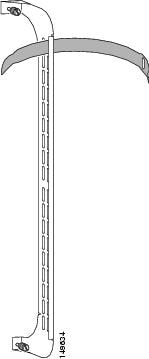
This section describes how to remove and install the PLIM cable management bracket. Figure 12 shows the PLIM cable management bracket.
Figure 12 PLIM Cable Management Bracket

Caution Do not use the cable management bracket alone as a handle to pull out or push in the PLIM. One hand must be under the PLIM to support its weight when carrying the PLIM. The cable management bracket is designed to hold the interface cables and may break if you use the bracket to push, pull, or carry the PLIM after it is removed from the router.
Required Tools and Equipment
You need the following tools and part to remove or install a PLIM cable management bracket:
Removing a PLIM Cable Management Bracket
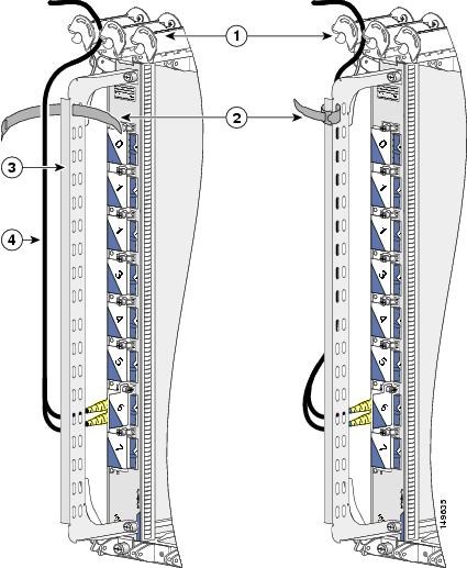
To remove a PLIM cable management bracket, see Figure 13 and follow these steps (the 10-GE PLIM is shown in the illustration, but the installation procedure is similar for all PLIMs):
Step 1
Attach an ESD-preventive wrist or ankle strap and follow its instructions for use.
Step 2
Note the current interface cable connections to the ports on each PLIM.
Step 3
Starting with the interface cable for the bottom port on the PLIM, disconnect the cable from the PLIM interface.

Note It is not necessary to remove the interface cables from the PLIM cable management bracket. The bracket (with attached cables) can be hooked to the chassis cable management bracket or a bracket on the chassis until a new PLIM is installed.
Step 4
Proceed upward and remove the interface from the Velcro strap on the end of the cable standoff (see Figure 13). Avoid any kinks or sharp bends in the cable.
Step 5
Repeat Starting with the interface cable for the bottom port on the PLIM, disconnect the cable from the PLIM interface. and Proceed upward and remove the interface from the Velcro strap on the end of the cable standoff (see Figure 13). Avoid any kinks or sharp bends in the cable. for all remaining interface cables, then proceed to Loosen the captive installation screw at each end of the cable management bracket and remove the bracket from the PLIM. .
Step 6
Loosen the captive installation screw at each end of the cable management bracket and remove the bracket from the PLIM.
Figure 13 PLIM Cable Management Installation and Removal
Installing a PLIM Cable Management Bracket
To install a PLIM cable management bracket, follow these steps:
Step 1
Attach an ESD-preventive wrist or ankle strap and follow its instructions for use.
Step 2
Attach the PLIM cable management bracket to the PLIM as follows:
a.
Position the cable management bracket over the front of the PLIM faceplate.
b.
Insert and tighten the captive screws to secure the bracket to the PLIM.
c.
Starting with the bottom port on the PLIM, connect each interface cable to the intended port.
Step 3
Carefully wrap the cables with the supplied Velcro strap (see Figure 13). Avoid any kinks or sharp bends in the cable.
Cabling and Specifications
The following sections provide specifications for POS and POS/DPT PLIMs:
- POS/SDH and DPT Interface Specifications
- OC-768c/STM-256c WDMPOS PLIM Interfaces
- PLIM Interface Cables
POS/SDH and DPT Interface Specifications
The POS and POS/DPT PLIMs and SFP modules provide full-duplex, 10-Gbps, laser-based, SONET/SDH-compliant interfaces. Table 4 , Table 5 , and Table 6 list the power budget and signal specifications of the optics for the POS and POS/DPT PLIMs. The actual distance in any given case depends on the quality of the fiber attached to the transceiver.
Table 5 1-Port OC-192c/STM-64c POS/DPT Optics Modules Power Specifications
Multimode2, very-short-reach, 850 nm
OC-768c/STM-256c WDMPOS PLIM Interfaces
Table 7 lists the optics specifications of the OC-768c/STM-256c WDMPOS PLIM.
Fully tunable from 1528.77 nm to 1563.86 nm across every other wavelength on the ITU 50-Ghz grid. For example:
1OC768-DPSK/C: 196.10THz, 196.00THz, 195.90THz, 195.80THz,...,191.70THz
1OC768-DPSK/C-O: 196.05 THz, 195.95 THz, 195.85 THz, 195.75THz,...,191.75THz
Chromatic disperson tolerance (1 dB OSNR3 penalty

PLIM Interface Cables
The following types of cables are used to connect the POS and POS/DPT PLIMs to another router or switch:

Note Fiber cables are not available from Cisco Systems. They can be purchased from cable vendors. The plug on the cable might have a dust cover attached. If so, remove the cover before connecting the cable.
The following types of cable connectors are used with the POS and POS/DPT PLIMs:
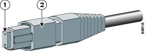
- Subscriber connector (SC)—See Figure 14
- Lucent connector (LC)— See Figure 15
- Multiple terminations push-pull latch (MTP)—See Figure 16. VSR uses a set of parallel fibers to transmit data.
Table 8 lists the cable and connector types for the four available OC-192c/STM-64c POS/DPT PLIMs. Simplex and duplex cables are supported.
Figure 14 Simplex SC Cable Connector (Single Mode)

Figure 15 Simplex LC Cable Connector
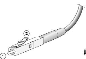
Figure 16 Simplex MTP Cable Connector (Multimode—VSR Only)
Removing and Installing Interface Cables
The following warning applies to single-mode connectors.

Warning Class 1 laser product. Statement 113
The following warning applies to multimode connectors.

Warning Class 1 LED product. Statement 126
To remove an interface cable, follow these steps:
Step 1
Attach the ESD-preventive wrist strap to your wrist and follow its instructions for use.
Step 2
Press on the spring-action disconnect latch to disconnect the cable from the interface ports (see Figure 14, Figure 15, or Figure 16).
Step 3
Slowly pull the connector from the port.

Warning Because invisible radiation may be emitted from the aperture of the port when no fiber cable is connected, avoid exposure to radiation and do not stare into open apertures. Statement 125
Step 4
Insert a dust plug into the optical port opening of each interface that is not being used.
To install an interface cable, follow these steps:
Step 1
Attach the ESD-preventive wrist strap to your wrist and follow its instructions for use.
Step 2
Remove the connector dust cover, if one is present.
Step 3
Align the connector end of the cable to the appropriate port. Observe the receive (RX) and transmit (TX) cable relationship.
Step 4
Insert the connector until it clicks and locks into place.
Connecting a DPT Ring
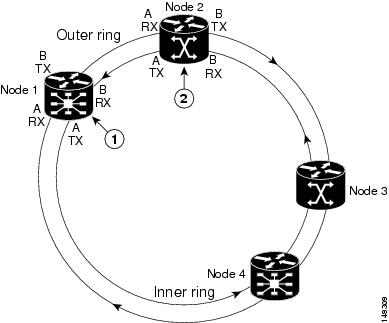
For DPT ports, the TX side A port on the line card must be connected to the RX side B port on the next node, and the RX side A port on the line card must be connected to the TX side B port on the next node. The labels next to the fiber connectors identify side A TX and RX and side B TX and RX.
As an example, Figure 17 illustrates the connections necessary to create a four-node DPT ring.
Figure 17 Creating a DPT Ring Using POS/DPT PLIMs
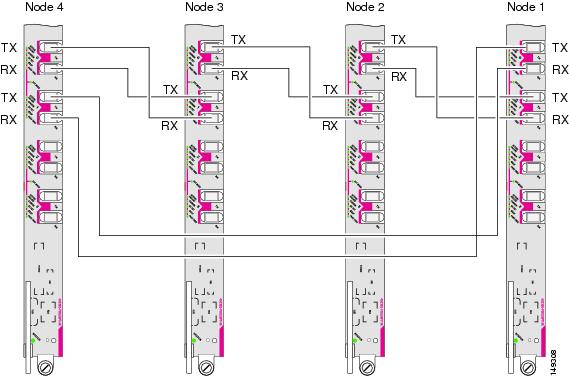
Use Table 9 and Figure 18 to help organize the cable connections for a four-node DPT ring.
Figure 18 Topology of Four Node DPT Ring

Note The fiber-optic connectors must be free of dust, oil, and other contaminants. Carefully clean the fiber- optic connectors using an alcohol wipe or other suitable cleanser.
Verifying the Installation of a PLIM
This section describes how to verify that the PLIM has been properly installed. See Figure 2, Figure 4, and Figure 5 for the location of the port and STATUS LEDs on the front panel of the POS and POS/DPT PLIMs.
Troubleshooting the PLIM
If a PLIM fails to operate or power up on installation:
- Make sure that the PLIM is seated firmly in the line card chassis slot. One easy way to verify physical installation is to see whether the front faceplate of the PLIM is even with the fronts of the other PLIMs installed in the card cage.
- Make sure that the corresponding MSC is installed and operating correctly.
- Check whether the ejector levers are latched and that the captive screws are fastened properly. If you are uncertain, unlatch the levers, loosen the screws, and attempt to reseat the PLIM.
- Determine whether there are any active alarms by looking at the alarm LEDs on the alarm module (16-slot) or route processor (8-slot). See Cisco CRS-1 Carrier Routing System Line Card Chassis System Description for more information about alarms.
- Examine the power shelves (16-slot chassis) or power distribution units (PDUs) (8-slot chassis) to see whether the chassis, as a whole, is receiving power.
Some PLIMs can operate in DPT mode (for example, the OC-192c/STM-64c POS/DPT PLIM). See the DPT LED descriptions in Table 10 to assist you with troubleshooting.
Use the LEDs on the PLIM to verify the correct installation and operation of the card. See “POS and DPT LED Descriptions” for more information.
POS and DPT LED Descriptions
The PLIM STATUS LED indicates the status of the PLIM. Port LEDs show the status of each fiber-optic connector. POS and DPT interfaces use the following port LEDs:
- ACTIVE/FAILURE—Indicates the active condition of this port.
- CARRIER—Indicates the status of SONET framing reception on this port.
- RX PKT or RX Packet—Indicates the status of packet reception on this port. It flashes when data is being received.
POS/DPT PLIMs use the following additional port LEDs:
- WRAP—Indicates a wrap on a DPT ring.
- PASS THRU—Indicates pass-through mode for DPT ports.
- DPT MODE—Indicates that a port pair is configured for DPT/SRP.
The port LEDs might not go on until after you have configured the PLIM interfaces (or turned them on, if they were shut down). To verify correct operation of each interface, complete the configuration procedures for the PLIM (see Cisco IOS XR Interface and Hardware Component Configuration Guide ). Table 10 shows the different operating states of the PLIM LEDs.
Port is active and the laser is on5.
DPT fiber misconnection was detected6 (for example, side A is connected to neighbor side A).
Port is in a local wrap condition, meaning the wrap is next to this port.
Port is operating normally. No wrap condition exists, or the port is not configured for DPT/SRP.
Port is operating normally, or it is not configured for DPT/SRP.
Port pair is configured for DPT/SRP. Each port pair has one LED, for example, 0 and 1, 2 and 3.
Obtaining Documentation
Cisco documentation and additional literature are available on Cisco.com. Cisco also provides several ways to obtain technical assistance and other technical resources. These sections explain how to obtain technical information from Cisco Systems.
Cisco.com
You can access the most current Cisco documentation at this URL:
http://www.cisco.com/univercd/home/home.htm
You can access the Cisco website at this URL:
Documentation DVD
Cisco documentation and additional literature are available in a Documentation DVD package, which may have shipped with your product. The Documentation DVD is updated regularly and may be more current than printed documentation. The Documentation DVD package is available as a single unit.
Registered Cisco.com users (Cisco direct customers) can order a Cisco Documentation DVD (product number DOC-DOCDVD=) from the Ordering tool or Cisco Marketplace.
Ordering Documentation
You can find instructions for ordering documentation at this URL:
http://www.cisco.com/univercd/cc/td/doc/es_inpck/pdi.htm
Documentation Feedback
You can send comments about technical documentation to bug-doc@cisco.com.
You can submit comments by using the response card (if present) behind the front cover of your document or by writing to the following address:
Cisco Systems
Attn: Customer Document Ordering
170 West Tasman Drive
San Jose, CA 95134-9883Cisco Product Security Overview
Cisco provides a free online Security Vulnerability Policy portal at this URL:
http://www.cisco.com/en/US/products/products_security_vulnerability_policy.html
From this site, you can perform these tasks:
- Report security vulnerabilities in Cisco products.
- Obtain assistance with security incidents that involve Cisco products.
- Register to receive security information from Cisco.
A current list of security advisories and notices for Cisco products is available at this URL:
If you prefer to see advisories and notices as they are updated in real time, you can access a Product Security Incident Response Team Really Simple Syndication (PSIRT RSS) feed from this URL:
http://www.cisco.com/en/US/products/products_psirt_rss_feed.html
Reporting Security Problems in Cisco Products
Cisco is committed to delivering secure products. We test our products internally before we release them, and we strive to correct all vulnerabilities quickly. If you think that you might have identified a vulnerability in a Cisco product, contact PSIRT:
- Emergencies — security-alert@cisco.com
- Non emergencies — psirt@cisco.com
Tip We encourage you to use Pretty Good Privacy (PGP) or a compatible product to encrypt any sensitive information that you send to Cisco. PSIRT can work from encrypted information that is compatible with PGP versions 2. x through 8. x .
Never use a revoked or an expired encryption key. The correct public key to use in your correspondence with PSIRT is the one that has the most recent creation date in this public key server list:
http://pgp.mit.edu:11371/pks/lookup?search=psirt%40cisco.com&op=index&exact=on
Obtaining Technical Assistance
For all customers, partners, resellers, and distributors who hold valid Cisco service contracts, Cisco Technical Support provides 24-hour-a-day, award-winning technical assistance. The Cisco Technical Support Website on Cisco.com features extensive online support resources. In addition, Cisco Technical Assistance Center (TAC) engineers provide telephone support. If you do not hold a valid Cisco service contract, contact your reseller.
Cisco Technical Support Website
The Cisco Technical Support Website provides online documents and tools for troubleshooting and resolving technical issues with Cisco products and technologies. The website is available 24 hours a day, 365 days a year, at this URL:
http://www.cisco.com/techsupport
Access to all tools on the Cisco Technical Support Website requires a Cisco.com user ID and password. If you have a valid service contract but do not have a user ID or password, you can register at this URL:
http://tools.cisco.com/RPF/register/register.do

Note Use the Cisco Product Identification (CPI) tool to locate your product serial number before submitting a web or phone request for service. You can access the CPI tool from the Cisco Technical Support Website by clicking the Tools & Resources link under Documentation & Tools. Choose Cisco Product Identification Tool from the Alphabetical Index drop-down list, or click the Cisco Product Identification Tool link under Alerts & RMAs. The CPI tool offers three search options: by product ID or model name; by tree view; or for certain products, by copying and pasting show command output. Search results show an illustration of your product with the serial number label location highlighted. Locate the serial number label on your product and record the information before placing a service call.
Submitting a Service Request
Using the online TAC Service Request Tool is the fastest way to open S3 and S4 service requests. (S3 and S4 service requests are those in which your network is minimally impaired or for which you require product information.) After you describe your situation, the TAC Service Request Tool provides recommended solutions. If your issue is not resolved using the recommended resources, your service request is assigned to a Cisco TAC engineer. The TAC Service Request Tool is located at this URL:
http://www.cisco.com/techsupport/servicerequest
For S1 or S2 service requests or if you do not have Internet access, contact the Cisco TAC by telephone. (S1 or S2 service requests are those in which your production network is down or severely degraded.) Cisco TAC engineers are assigned immediately to S1 and S2 service requests to help keep your business operations running smoothly.
To open a service request by telephone, use one of the following numbers:
Asia-Pacific: +61 2 8446 7411 (Australia: 1 800 805 227)
EMEA: +32 2 704 55 55
USA: 1 800 553-2447Definitions of Service Request Severity
To ensure that all service requests are reported in a standard format, Cisco has established severity definitions.
Severity 1 (S1)—Your network is “down,” or there is a critical impact to your business operations. You and Cisco will commit all necessary resources around the clock to resolve the situation.
Severity 2 (S2)—Operation of an existing network is severely degraded, or significant aspects of your business operation are negatively affected by inadequate performance of Cisco products. You and Cisco will commit full-time resources during normal business hours to resolve the situation.
Severity 3 (S3)—Operational performance of your network is impaired, but most business operations remain functional. You and Cisco will commit resources during normal business hours to restore service to satisfactory levels.
Severity 4 (S4)—You require information or assistance with Cisco product capabilities, installation, or configuration. There is little or no effect on your business operations.
Obtaining Additional Publications and Information
Information about Cisco products, technologies, and network solutions is available from various online and printed sources.
- Cisco Marketplace provides a variety of Cisco books, reference guides, and logo merchandise. Visit Cisco Marketplace, the company store, at this URL:
http://www.cisco.com/go/marketplace/
- Cisco Press publishes a wide range of general networking, training and certification titles. Both new and experienced users will benefit from these publications. For current Cisco Press titles and other information, go to Cisco Press at this URL:
- Packet magazine is the Cisco Systems technical user magazine for maximizing Internet and networking investments. Each quarter, Packet delivers coverage of the latest industry trends, technology breakthroughs, and Cisco products and solutions, as well as network deployment and troubleshooting tips, configuration examples, customer case studies, certification and training information, and links to scores of in-depth online resources. You can access Packet magazine at this URL:
- iQ Magazine is the quarterly publication from Cisco Systems designed to help growing companies learn how they can use technology to increase revenue, streamline their business, and expand services. The publication identifies the challenges facing these companies and the technologies to help solve them, using real-world case studies and business strategies to help readers make sound technology investment decisions. You can access iQ Magazine at this URL:
http://www.cisco.com/go/iqmagazine
- Internet Protocol Journal is a quarterly journal published by Cisco Systems for engineering professionals involved in designing, developing, and operating public and private internets and intranets. You can access the Internet Protocol Journal at this URL:
- World-class networking training is available from Cisco. You can view current offerings at this URL:
http://www.cisco.com/en/US/learning/index.html
This document is to be used in conjunction with the documents listed in the “Related Documentation” section.Cisco and the Cisco logo are trademarks or registered trademarks of Cisco and/or its affiliates in the U.S. and other countries. To view a list of Cisco trademarks, go to this URL: www.cisco.com/go/trademarks . Third-party trademarks mentioned are the property of their respective owners. The use of the word partner does not imply a partnership relationship between Cisco and any other company. (1110R)
Contact Cisco
- Open a Support Case

- (Requires a Cisco Service Contract)
 Feedback