- About this Guide
-
- Information About Cisco Unified Communications Features
- Using the Cisco Unified Communication Wizard
- Configuring the Cisco Phone Proxy
- Configuring the TLS Proxy for Encrypted Voice Inspection
- Configuring Cisco Mobility Advantage
- Configuring Cisco Unified Presence
- Configuring Cisco Unified Communications Intercompany Media Engine
- Index
- Information About Network Object NAT
- Licensing Requirements for Network Object NAT
- Prerequisites for Network Object NAT
- Guidelines and Limitations
- Default Settings
- Configuring Network Object NAT
- Monitoring Network Object NAT
- Configuration Examples for Network Object NAT
- Providing Access to an Inside Web Server (Static NAT)
- NAT for Inside Hosts (Dynamic NAT) and NAT for an Outside Web Server (StaticNAT)
- Inside Load Balancer with Multiple Mapped Addresses (Static NAT, One-to-Many)
- Single Address for FTP, HTTP, and SMTP (Static NAT-with-Port-Translation)
- DNS Server on Mapped Interface, Web Server on Real Interface (Static NAT with DNS Modification)
- DNS Server and FTP Server on Mapped Interface, FTP Server is Translated (Static NAT with DNS Modification)
- IPv4 DNS Server and FTP Server on Mapped Interface, IPv6 Host on Real Interface (Static NAT64 with DNS64 Modification)
- Feature History for Network Object NAT
Configuring Network Object NAT
All NAT rules that are configured as a parameter of a network object are considered to be network object NAT rules. Network object NAT is a quick and easy way to configure NAT for a single IP address, a range of addresses, or a subnet. After you configure the network object, you can then identify the mapped address for that object.
This chapter describes how to configure network object NAT, and it includes the following sections:
- Information About Network Object NAT
- Licensing Requirements for Network Object NAT
- Prerequisites for Network Object NAT
- Guidelines and Limitations
- Default Settings
- Configuring Network Object NAT
- Monitoring Network Object NAT
- Configuration Examples for Network Object NAT
- Feature History for Network Object NAT

Note For detailed information about how NAT works, see Chapter3, “Information About NAT”
Information About Network Object NAT
When a packet enters the ASA, both the source and destination IP addresses are checked against the network object NAT rules. The source and destination address in the packet can be translated by separate rules if separate matches are made. These rules are not tied to each other; different combinations of rules can be used depending on the traffic.
Because the rules are never paired, you cannot specify that a source address should be translated to A when going to destination X, but be translated to B when going to destination Y. Use twice NAT for that kind of functionality (twice NAT lets you identify the source and destination address in a single rule).
For detailed information about the differences between twice NAT and network object NAT, see the “How NAT is Implemented” section.
Network object NAT rules are added to section 2 of the NAT rules table. For more information about NAT ordering, see the “NAT Rule Order” section.
Licensing Requirements for Network Object NAT
The following table shows the licensing requirements for this feature:
Prerequisites for Network Object NAT
Depending on the configuration, you can configure the mapped address inline if desired or you can create a separate network object or network object group for the mapped address (the object network or object-group network command). Network object groups are particularly useful for creating a mapped address pool with discontinous IP address ranges or multiple hosts or subnets. To create a network object or group, see the general operations configuration guide.
For specific guidelines for objects and groups, see the configuration section for the NAT type you want to configure. See also the “Guidelines and Limitations” section.
Guidelines and Limitations
Supported in single and multiple context mode.
- Supported in routed and transparent firewall mode.
- In transparent mode, you must specify the real and mapped interfaces; you cannot use any .
- In transparent mode, you cannot configure interface PAT, because the transparent mode interfaces do not have IP addresses. You also cannot use the management IP address as a mapped address.
- In transparent mode, translating between IPv4 and IPv6 networks is not supported. Translating between two IPv6 networks, or between two IPv4 networks is supported.
- Supports IPv6. See also the “NAT and IPv6” section.
- For routed mode, you can also translate between IPv4 and IPv6.
- For transparent mode, translating between IPv4 and IPv6 networks is not supported. Translating between two IPv6 networks, or between two IPv4 networks is supported.
- For transparent mode, a PAT pool is not supported for IPv6.
- For static NAT, you can specify an IPv6 subnet up to /64. Larger subnets are not supported.
- When using FTP with NAT46, when an IPv4 FTP client connects to an IPv6 FTP server, the client must use either the extended passive mode (EPSV) or extended port mode (EPRT); PASV and PORT commands are not supported with IPv6.
- You can only define a single NAT rule for a given object; if you want to configure multiple NAT rules for an object, you need to create multiple objects with different names that specify the same IP address, for example, object network obj-10.10.10.1-01 , object network obj-10.10.10.1-02 , and so on.
- If you change the NAT configuration, and you do not want to wait for existing translations to time out before the new NAT configuration is used, you can clear the translation table using the clear xlate command. However, clearing the translation table disconnects all current connections that use translations.

Note If you remove a dynamic NAT or PAT rule, and then add a new rule with mapped addresses that overlap the addresses in the removed rule, then the new rule will not be used until all connections associated with the removed rule time out or are cleared using the clear xlate command. This safeguard ensures that the same address is not assigned to multiple hosts.
- Objects and object groups used in NAT cannot be undefined; they must include IP addresses.
- You cannot use an object group with both IPv4 and IPv6 addresses; the object group must include only one type of address.
- You can use the same mapped object or group in multiple NAT rules.
- The mapped IP address pool cannot include:
– The mapped interface IP address. If you specify any interface for the rule, then all interface IP addresses are disallowed. For interface PAT (routed mode only), use the interface keyword instead of the IP address.
– (Transparent mode) The management IP address.
– (Dynamic NAT) The standby interface IP address when VPN is enabled.
– Existing VPN pool addresses.
- For application inspection limitations with NAT or PAT, see the “Default Settings and NAT Limitations” section in Chapter9, “Getting Started with Application Layer Protocol Inspection”
Default Settings
- (Routed mode) The default real and mapped interface is Any, which applies the rule to all interfaces.
- The default behavior for identity NAT has proxy ARP enabled, matching other static NAT rules. You can disable proxy ARP if desired. See the “Routing NAT Packets” section for more information.
- If you specify an optional interface, then the ASA uses the NAT configuration to determine the egress interface, but you have the option to always use a route lookup instead. See the “Routing NAT Packets” section for more information.
Configuring Network Object NAT
This section describes how to configure network object NAT and includes the following topics:
- Adding Network Objects for Mapped Addresses
- Configuring Dynamic NAT
- Configuring Dynamic PAT (Hide)
- Configuring Static NAT or Static NAT-with-Port-Translation
- Configuring Identity NAT
- Configuring Per-Session PAT Rules
Adding Network Objects for Mapped Addresses
For dynamic NAT, you must use an object or group for the mapped addresses. Other NAT types have the option of using inline addresses, or you can create an object or group according to this section. For more information about configuring a network object or group, see the general operations configuration guide.
Guidelines
- A network object group can contain objects and/or inline addresses of either IPv4 or IPv6 addresses. The group cannot contain both IPv4 and IPv6 addresses; it must contain one type only.
- See the “Guidelines and Limitations” section for information about disallowed mapped IP addresses.
- Dynamic NAT:
– You cannot use an inline address; you must configure a network object or group.
– The object or group cannot contain a subnet; the object must define a range; the group can include hosts and ranges.
– If a mapped network object contains both ranges and host IP addresses, then the ranges are used for dynamic NAT, and then the host IP addresses are used as a PAT fallback.
– Instead of using an object, you can optionally configure an inline host address or specify the interface address.
– If you use an object, the object or group cannot contain a subnet; the object must define a host, or for a PAT pool, a range; the group (for a PAT pool) can include hosts and ranges.
– Instead of using an object, you can configure an inline address or specify the interface address (for static NAT-with-port-translation).
– If you use an object, the object or group can contain a host, range, or subnet.
– Instead of using an object, you can configure an inline address.
– If you use an object, the object must match the real addresses you want to translate.
Detailed Steps
Configuring Dynamic NAT
This section describes how to configure network object NAT for dynamic NAT. For more information, see the “Dynamic NAT” section.
Detailed Steps
See the “Adding Network Objects for Mapped Addresses” section. |
||
Configures a network object for which you want to configure NAT, or enters object network configuration mode for an existing network object. |
||
{ host ip_address | subnet subnet_address netmask | range ip_address_1 ip_address_2 } ciscoasa(config-network-object)# subnet 10.1.1.0 255.255.255.0 |
If you are creating a new network object, defines the real IP address(es) (either IPv4 or IPv6) that you want to translate. |
|
nat [ ( real_ifc , mapped_ifc ) ] dynamic mapped_obj [ interface [ ipv6 ]] [ dns ] ciscoasa(config-network-object)# nat (inside,outside) dynamic MAPPED_IPS interface |
Configures dynamic NAT for the object IP addresses. Note You can only define a single NAT rule for a given object. See the “Additional Guidelines” section.
– An existing network object (see Step 1). – An existing network object group (see Step 1).
|
Examples
The following example configures dynamic NAT that hides 192.168.2.0 network behind a range of outside addresses 10.2.2.1 through 10.2.2.10:
The following example configures dynamic NAT with dynamic PAT backup. Hosts on inside network 10.76.11.0 are mapped first to the nat-range1 pool (10.10.10.10-10.10.10.20). After all addresses in the nat-range1 pool are allocated, dynamic PAT is performed using the pat-ip1 address (10.10.10.21). In the unlikely event that the PAT translations are also used up, dynamic PAT is performed using the outside interface address.
The following example configures dynamic NAT with dynamic PAT backup to translate IPv6 hosts to IPv4. Hosts on inside network 2001:DB8::/96 are mapped first to the IPv4_NAT_RANGE pool (209.165.201.1 to 209.165.201.30). After all addresses in the IPv4_NAT_RANGE pool are allocated, dynamic PAT is performed using the IPv4_PAT address (209.165.201.31). In the event that the PAT translations are also used up, dynamic PAT is performed using the outside interface address.
Configuring Dynamic PAT (Hide)
This section describes how to configure network object NAT for dynamic PAT (hide). For more information, see the “Dynamic PAT” section.
Guidelines
- If available, the real source port number is used for the mapped port. However, if the real port is not available, by default the mapped ports are chosen from the same range of ports as the real port number: 0 to 511, 512 to 1023, and 1024 to 65535. Therefore, ports below 1024 have only a small PAT pool that can be used. (8.4(3) and later, not including 8.5(1) or 8.6(1)) If you have a lot of traffic that uses the lower port ranges, you can now specify a flat range of ports to be used instead of the three unequal-sized tiers: either 1024 to 65535, or 1 to 65535.
- If you use the same PAT pool object in two separate rules, then be sure to specify the same options for each rule. For example, if one rule specifies extended PAT and a flat range, then the other rule must also specify extended PAT and a flat range.
For extended PAT for a PAT pool:
- Many application inspections do not support extended PAT. See the “Default Settings and NAT Limitations” section in “Getting Started with Application Layer Protocol Inspection,” for a complete list of unsupported inspections.
- If you enable extended PAT for a dynamic PAT rule, then you cannot also use an address in the PAT pool as the PAT address in a separate static NAT-with-port-translation rule. For example, if the PAT pool includes 10.1.1.1, then you cannot create a static NAT-with-port-translation rule using 10.1.1.1 as the PAT address.
- If you use a PAT pool and specify an interface for fallback, you cannot specify extended PAT.
- For VoIP deployments that use ICE or TURN, do not use extended PAT. ICE and TURN rely on the PAT binding to be the same for all destinations.
For round robin for a PAT pool:
- If a host has an existing connection, then subsequent connections from that host will use the same PAT IP address if ports are available. Note : This “stickiness” does not survive a failover. If the ASA fails over, then subsequent connections from a host may not use the initial IP address.
- Round robin, especially when combined with extended PAT, can consume a large amount of memory. Because NAT pools are created for every mapped protocol/IP address/port range, round robin results in a large number of concurrent NAT pools, which use memory. Extended PAT results in an even larger number of concurrent NAT pools.
Detailed Steps
(Optional) Create a network object or group for the mapped addresses. |
See the “Adding Network Objects for Mapped Addresses” section. |
|
Configures a network object for which you want to configure NAT, or enters object network configuration mode for an existing network object. |
||
{ host ip_address | subnet subnet_address netmask | range ip_address_1 ip_address_2 } |
If you are creating a new network object, defines the real IP address(es) (either IPv4 or IPv6) that you want to translate. |
|
nat [ ( real_ifc , mapped_ifc ) ] dynamic { mapped_inline_host_ip | mapped_obj | pat-pool mapped_obj [ round-robin ] [ extended ] [ flat [ include-reserve ]] | interface [ ipv6 ]} [ interface [ ipv6 ]] [ dns ] ciscoasa(config-network-object)# nat (any,outside) dynamic interface |
Configures dynamic PAT for the object IP addresses. You can only define a single NAT rule for a given object. See the “Additional Guidelines” section.
– An existing network object that is defined as a host address (see Step 1). – pat-pool —An existing network object or group that contains multiple addresses. – interface —(Routed mode only) The IP address of the mapped interface is used as the mapped address. If you specify ipv6 , then the IPv6 address of the interface is used. For this option, you must configure a specific interface for the mapped_ifc . You must use this keyword when you want to use the interface IP address; you cannot enter it inline or as an object. – Round robin—The round-robin keyword enables round-robin address allocation for a PAT pool. Without round robin, by default all ports for a PAT address will be allocated before the next PAT address is used. The round-robin method assigns an address/port from each PAT address in the pool before returning to use the first address again, and then the second address, and so on. |
|
|
– Extended PAT—The extended keyword enables extended PAT. Extended PAT uses 65535 ports per service , as opposed to per IP address, by including the destination address and port in the translation information. Normally, the destination port and address are not considered when creating PAT translations, so you are limited to 65535 ports per PAT address. For example, with extended PAT, you can create a translation of 10.1.1.1:1027 when going to 192.168.1.7:23 as well as a translation of 10.1.1.1:1027 when going to 192.168.1.7:80. – Flat range—The flat keyword enables use of the entire 1024 to 65535 port range when allocating ports. When choosing the mapped port number for a translation, the ASA uses the real source port number if it is available. However, without this option, if the real port is not available, by default the mapped ports are chosen from the same range of ports as the real port number: 1 to 511, 512 to 1023, and 1024 to 65535. To avoid running out of ports at the low ranges, configure this setting. To use the entire range of 1 to 65535, also specify the include-reserve keyword.
|
Examples
The following example configures dynamic PAT that hides the 192.168.2.0 network behind address 10.2.2.2:
The following example configures dynamic PAT that hides the 192.168.2.0 network behind the outside interface address:
The following example configures dynamic PAT with a PAT pool to translate the inside IPv6 network to an outside IPv4 network:
ciscoasa(config)# object network IPv4_POOL
ciscoasa(config-network-object)# range 203.0.113.1 203.0.113.254
Configuring Static NAT or Static NAT-with-Port-Translation
This section describes how to configure a static NAT rule using network object NAT. For more information, see the “Static NAT” section.
Detailed Steps
(Optional) Create a network object or group for the mapped addresses. |
See the “Adding Network Objects for Mapped Addresses” section. |
|
Configures a network object for which you want to configure NAT, or enters object network configuration mode for an existing network object. |
||
{ host ip_address | subnet subnet_address netmask | range ip_address_1 ip_address_2 } ciscoasa(config-network-object)# subnet 10.2.1.0 255.255.255.0 |
If you are creating a new network object, defines the real IP address(es) (IPv4 or IPv6) that you want to translate. |
|
nat [ ( real_ifc , mapped_ifc ) ] static { mapped_inline_ip | mapped_obj | interface [ ipv6 ]} [ net-to-net ] [ dns | service { tcp | udp } real_port mapped_port ] [ no-proxy-arp ] ciscoasa(config-network-object)# nat (inside,outside) static MAPPED_IPS service tcp 80 8080 |
Configures static NAT for the object IP addresses. You can only define a single NAT rule for a given object.
– An inline IP address. The netmask or range for the mapped network is the same as that of the real network. For example, if the real network is a host, then this address will be a host address. In the case of a range, then the mapped addresses include the same number of addresses as the real range. For example, if the real address is defined as a range from 10.1.1.1 through 10.1.1.6, and you specify 172.20.1.1 as the mapped address, then the mapped range will include 172.20.1.1 through 172.20.1.6. – An existing network object or group (see Step 1). – interface —(Static NAT-with-port-translation only; routed mode) For this option, you must configure a specific interface for the mapped_ifc . If you specify ipv6 , then the IPv6 address of the interface is used. Be sure to also configure the service keyword. Typically, you configure the same number of mapped addresses as real addresses for a one-to-one mapping. You can, however, have a mismatched number of addresses. See the “Static NAT” section.
|
Examples
The following example configures static NAT for the real host 10.1.1.1 on the inside to 10.2.2.2 on the outside with DNS rewrite enabled.
The following example configures static NAT for the real host 10.1.1.1 on the inside to 10.2.2.2 on the outside using a mapped object.
The following example configures static NAT-with-port-translation for 10.1.1.1 at TCP port 21 to the outside interface at port 2121.
The following example maps an inside IPv4 network to an outside IPv6 network.
The following example maps an inside IPv6 network to an outside IPv6 network.
Configuring Identity NAT
This section describes how to configure an identity NAT rule using network object NAT. For more information, see the “Identity NAT” section.
Detailed Steps
(Optional) Create a network object for the mapped addresses. |
The object must include the same addresses that you want to translate. See the “Adding Network Objects for Mapped Addresses” section. |
|
Configures a network object for which you want to perform identity NAT, or enters object network configuration mode for an existing network object. This network object has a different name from the mapped network object (see Step 1) even though they both contain the same IP addresses. |
||
{ host ip_address | subnet subnet_address netmask | range ip_address_1 ip_address_2 } ciscoasa(config-network-object)# subnet 10.1.1.0 255.255.255.0 |
If you are creating a new network object, defines the real IP address(es) (IPv4 or IPv6) to which you want to perform identity NAT. If you configured a network object for the mapped addresses in Step 1, then these addresses must match. |
|
nat [ ( real_ifc , mapped_ifc ) ] static { mapped_inline_ip | mapped_obj } [ no-proxy-arp ] [ route-lookup ] ciscoasa(config-network-object)# nat (inside,outside) static MAPPED_IPS |
Configures identity NAT for the object IP addresses. Note You can only define a single NAT rule for a given object. See the “Additional Guidelines” section.
– Network object—Including the same IP address as the real object (see Step 1). – Inline IP address—The netmask or range for the mapped network is the same as that of the real network. For example, if the real network is a host, then this address will be a host address. In the case of a range, then the mapped addresses include the same number of addresses as the real range. For example, if the real address is defined as a range from 10.1.1.1 through 10.1.1.6, and you specify 10.1.1.1 as the mapped address, then the mapped range will include 10.1.1.1 through 10.1.1.6.
|
Example
The following example maps a host address to itself using an inline mapped address:
ciscoasa(config)# object network my-host-obj1
ciscoasa(config-network-object)# host 10.1.1.1
ciscoasa(config-network-object)# nat (inside,outside) static 10.1.1.1
The following example maps a host address to itself using a network object:
ciscoasa(config)# object network my-host-obj1-identity
ciscoasa(config-network-object)# host 10.1.1.1
ciscoasa(config-network-object)# object network my-host-obj1
ciscoasa(config-network-object)# host 10.1.1.1
ciscoasa(config-network-object)# nat (inside,outside) static my-host-obj1-identity
Configuring Per-Session PAT Rules
By default, all TCP PAT traffic and all UDP DNS traffic uses per-session PAT. To use multi-session PAT for traffic, you can configure per-session PAT rules: a permit rule uses per-session PAT, and a deny rule uses multi-session PAT. For more information about per-session vs. multi-session PAT, see the “Per-Session PAT vs. Multi-Session PAT” section.
Defaults
By default, the following rules are installed:

Note You cannot remove these rules, and they always exist after any manually-created rules. Because rules are evaluated in order, you can override the default rules. For example, to completely negate these rules, you could add the following:
Detailed Steps
Monitoring Network Object NAT
To monitor object NAT, enter one of the following commands:
Configuration Examples for Network Object NAT
This section includes the following configuration examples:
- Providing Access to an Inside Web Server (Static NAT)
- NAT for Inside Hosts (Dynamic NAT) and NAT for an Outside Web Server (Static NAT)
- Inside Load Balancer with Multiple Mapped Addresses (Static NAT, One-to-Many)
- Single Address for FTP, HTTP, and SMTP (Static NAT-with-Port-Translation)
- DNS Server on Mapped Interface, Web Server on Real Interface (Static NAT with DNS Modification)
- DNS Server and FTP Server on Mapped Interface, FTP Server is Translated (Static NAT with DNS Modification)
- IPv4 DNS Server and FTP Server on Mapped Interface, IPv6 Host on Real Interface (Static NAT64 with DNS64 Modification)
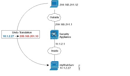
Providing Access to an Inside Web Server (Static NAT)
The following example performs static NAT for an inside web server. The real address is on a private network, so a public address is required. Static NAT is necessary so hosts can initiate traffic to the web server at a fixed address. (See Figure 4-1).
Figure 4-1 Static NAT for an Inside Web Server
Step 1 Create a network object for the internal web server:
Step 2 Define the web server address:
Step 3 Configure static NAT for the object:
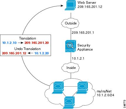
NAT for Inside Hosts (Dynamic NAT) and NAT for an Outside Web Server (Static NAT)
The following example configures dynamic NAT for inside users on a private network when they access the outside. Also, when inside users connect to an outside web server, that web server address is translated to an address that appears to be on the inside network. (See Figure 4-2).
Figure 4-2 Dynamic NAT for Inside, Static NAT for Outside Web Server
Step 1 Create a network object for the dynamic NAT pool to which you want to translate the inside addresses:
Step 2 Create a network object for the inside network:
Step 3 Enable dynamic NAT for the inside network:
Step 4 Create a network object for the outside web server:
Step 5 Define the web server address:
Step 6 Configure static NAT for the web server:
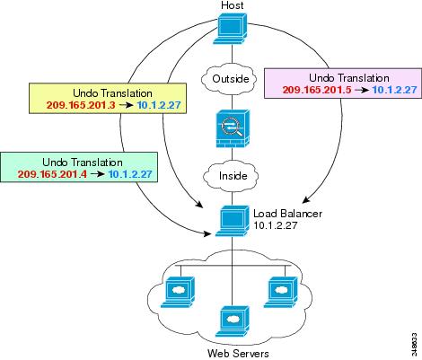
Inside Load Balancer with Multiple Mapped Addresses (Static NAT, One-to-Many)
The following example shows an inside load balancer that is translated to multiple IP addresses. When an outside host accesses one of the mapped IP addresses, it is untranslated to the single load balancer address. Depending on the URL requested, it redirects traffic to the correct web server. (See Figure 4-3).
Figure 4-3 Static NAT with One-to-Many for an Inside Load Balancer
Step 1 Create a network object for the addresses to which you want to map the load balancer:
Step 2 Create a network object for the load balancer:
Step 3 Define the load balancer address:
Step 4 Configure static NAT for the load balancer:
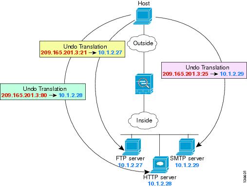
Single Address for FTP, HTTP, and SMTP (Static NAT-with-Port-Translation)
The following static NAT-with-port-translation example provides a single address for remote users to access FTP, HTTP, and SMTP. These servers are actually different devices on the real network, but for each server, you can specify static NAT-with-port-translation rules that use the same mapped IP address, but different ports. (See Figure 4-4.)
Figure 4-4 Static NAT-with-Port-Translation
Step 1 Create a network object for the FTP server address:
Step 2 Define the FTP server address, and configure static NAT with identity port translation for the FTP server:
Step 3 Create a network object for the HTTP server address:
Step 4 Define the HTTP server address, and configure static NAT with identity port translation for the HTTP server:
Step 5 Create a network object for the SMTP server address:
Step 6 Define the SMTP server address, and configure static NAT with identity port translation for the SMTP server:
DNS Server on Mapped Interface, Web Server on Real Interface (Static NAT with DNS Modification)
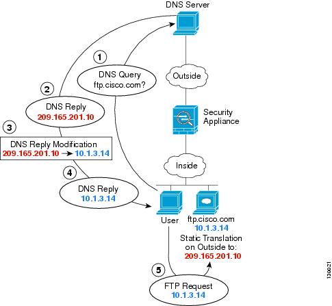
For example, a DNS server is accessible from the outside interface. A server, ftp.cisco.com, is on the inside interface. You configure the ASA to statically translate the ftp.cisco.com real address (10.1.3.14) to a mapped address (209.165.201.10) that is visible on the outside network. (See Figure 4-5.) In this case, you want to enable DNS reply modification on this static rule so that inside users who have access to ftp.cisco.com using the real address receive the real address from the DNS server, and not the mapped address.
When an inside host sends a DNS request for the address of ftp.cisco.com, the DNS server replies with the mapped address (209.165.201.10). The ASA refers to the static rule for the inside server and translates the address inside the DNS reply to 10.1.3.14. If you do not enable DNS reply modification, then the inside host attempts to send traffic to 209.165.201.10 instead of accessing ftp.cisco.com directly.
Figure 4-5 DNS Reply Modification
Step 1 Create a network object for the FTP server address:
Step 2 Define the FTP server address, and configure static NAT with DNS modification:
DNS Server and FTP Server on Mapped Interface, FTP Server is Translated (Static NAT with DNS Modification)
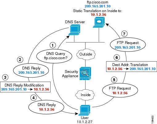
Figure 4-6 shows an FTP server and DNS server on the outside. The ASA has a static translation for the outside server. In this case, when an inside user requests the address for ftp.cisco.com from the DNS server, the DNS server responds with the real address, 209.165.201.10. Because you want inside users to use the mapped address for ftp.cisco.com (10.1.2.56) you need to configure DNS reply modification for the static translation.
Figure 4-6 DNS Reply Modification Using Outside NAT
Step 1 Create a network object for the FTP server address:
Step 2 Define the FTP server address, and configure static NAT with DNS modification:
IPv4 DNS Server and FTP Server on Mapped Interface, IPv6 Host on Real Interface (Static NAT64 with DNS64 Modification)
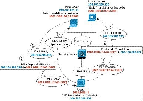
Figure 4-6 shows an FTP server and DNS server on the outside IPv4 network. The ASA has a static translation for the outside server. In this case, when an inside IPv6 user requests the address for ftp.cisco.com from the DNS server, the DNS server responds with the real address, 209.165.200.225. Because you want inside users to use the mapped address for ftp.cisco.com (2001:DB8::D1A5:C8E1) you need to configure DNS reply modification for the static translation. This example also includes a static NAT translation for the DNS server, and a PAT rule for the inside IPv6 hosts.
Figure 4-7 DNS Reply Modification Using Outside NAT
Step 1 Configure static NAT with DNS modification for the FTP server.
a. Create a network object for the FTP server address.
b. Define the FTP server address, and configure static NAT with DNS modification and, because this is a one-to-one translation, configure the net-to-net method for NAT46.
Step 2 Configure NAT for the DNS server.
a. Create a network object for the DNS server address.
b. Define the DNS server address, and configure static NAT using the net-to-net method.
Step 3 Configure an IPv4 PAT pool for translating the inside IPv6 network.
ciscoasa(config)# object network IPv4_POOL
ciscoasa(config-network-object)# range 203.0.113.1 203.0.113.254
Step 4 Configure PAT for the inside IPv6 network.
a. Create a network object for the inside IPv6 network.
b. Define the IPv6 network address, and configure dynamic NAT using a PAT pool.
Feature History for Network Object NAT
Table 4-1 lists each feature change and the platform release in which it was implemented.
 Feedback