About the ASA 5500-X
This chapter describes the Cisco ASA 5512-X, 5515-X, 5525-X, 5545-X, and 5555-X models. We recommend that you read this entire guide before beginning any of the procedures contained herein.
Warning![]() : Only trained and qualified personnel should install, replace, or service this equipment. Statement 49
: Only trained and qualified personnel should install, replace, or service this equipment. Statement 49
Note![]() : Your ASA 5500-X ships with either ASA or Firepower Threat Defense software preinstalled. To reimage your device, see Reimage the Cisco ASA or Firepower Threat Defense Device.
: Your ASA 5500-X ships with either ASA or Firepower Threat Defense software preinstalled. To reimage your device, see Reimage the Cisco ASA or Firepower Threat Defense Device.
Package Contents
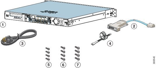
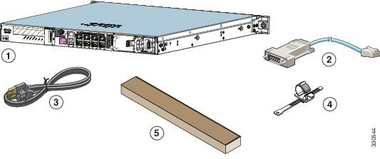
This section lists the package contents of each chassis. Note that contents are subject to change, and your exact contents might contain additional or fewer items.
ASA 5512-X, ASA 5515-X, or ASA 5525-X
|
|
|
Blue Console Cable and Serial PC Terminal Adapter (DB-9 to RJ-45) |
|
|
|
|
||
|
|
|
||
|
|
|||
ASA 5545-X and ASA 5555-X
|
|
|
Blue Console Cable and Serial PC Terminal Adapter (DB-9 to RJ-45) |
|
|
|
|
||
|
|
|||
Internal and External USB Flash Drives
The Cisco ASA 5500-X has internal and (optional) external USB drives.
- Internal USB Drive
- External USB Drives (Optional)
- USB Online Insertion and Removal
- FAT-32 File System
Internal USB Drive
An embedded USB (eUSB) device is used as the internal flash ( disk0). See Hardware Specifications for the size shipped with each model.
External USB Drives (Optional)
The ASA 5500-X supports external USB flash drives for data storage. The ASA 5500-X uses disk1 as the external USB flash drive identifier. When the ASA is powered on, an inserted USB flash drive is mounted to disk1 and available for you to use. Additionally, the file system commands that are available to disk 0 are also available to disk1, including copy, format, delete, mkdir, pwd, cd, and so on. When you remove the USB flash drive, the system unmounts disk1, and disk1 becomes an invalid file system label that you can no longer access.
If you insert a USB drive with more than one partition, only the first partition is mounted.
USB Online Insertion and Removal
While the ASA back panel has two USB slots, only one is supported for online insertion and removal (OIR), with priority given to the USB drive that was inserted first. For example, based on the time sequence, the first inserted USB flash drive is mounted to disk1, regardless of the slot in which you insert it. When you insert a second USB device, an error message appears on the console to notify you that an extra, unsupported USB flash drive exists. Removing either one of the USB devices does not change the priority that you just established. To change the priority you must safely remove the USB device and begin again to establish the desired priority.
FAT-32 File System
The ASA 5500-X supports only FAT-32-formatted file systems for the eUSB and external USB drives. If you insert an external USB drive that is not in FAT-32 format, the system mounting process fails, and you receive an error message. You can enter the format disk1: command to format the partition to FAT 32 and mount the partition to disk1 again; however, data might be lost.
Solid State Drives
You must install a Cisco Solid State Drive (SSD) for use with the some software modules. Only Cisco SSDs are supported. You can install one SSD in the ASA 5512-X, ASA 5515-X, and ASA 5525-X. You can install two SSDs in a RAID 1 configuration in the ASA 5545-X and ASA 5555-X.
Note![]() : When you install an SSD for the first time, you must reload the ASA and then reimage the installed module.
: When you install an SSD for the first time, you must reload the ASA and then reimage the installed module.
The SSD is hot-swappable. The SSD resides in a carrier, which you install into the drive bay. You can use the SSD with an AC or DC power supply. See Install and Remove a Solid State Drive for a Services Module for more information.
Alarm LED
The ASA 5500-X performs autonomous environmental monitoring, polling all external sensors and monitoring operating conditions. In the event of damage to certain internal components, or surpassed temperature thresholds, the system activates an alarm LED to notify you of a critical condition. For example, the alarm LED is activated by firmware in the event of various critical over-voltage and over-temperature conditions, as well as when the ASA has missing or unrecognized internal chip components. When the alarm LED lights, you can find details about the system condition from the system message that appears on the console, or by entering the show environment or show controller pci CLI commands.
Note![]() : If you remove one of the power-supply modules from an ASA with redundant power supplies—in other words, one with two power supplies installed—the Alarm LED will light. To turn off the light, you must power-cycle the chassis; that is, turn it completely off and then turn it back on. See Power Supply for more information about the redundant power-supply configuration. See Remove and Install the Power Supply for more information about removing a power supply.
: If you remove one of the power-supply modules from an ASA with redundant power supplies—in other words, one with two power supplies installed—the Alarm LED will light. To turn off the light, you must power-cycle the chassis; that is, turn it completely off and then turn it back on. See Power Supply for more information about the redundant power-supply configuration. See Remove and Install the Power Supply for more information about removing a power supply.
ASA 5500-X I/O Cards
The ASA 5500-X six-port GigabitEthernet interface cards extend the I/O capabilities of the ASA 5525-X, ASA 5545-X, and ASA 5555-X models by providing additional GigabitEthernet ports.
The I/O cards provide the following benefits:
- Segmentation of network traffic into separate security zones
- Fiber-optic cable connectivity for communications over long distances
- Load-sharing of traffic, and protection against link failure, using EtherChannel
- Support for Jumbo Ethernet frames of up to 9000 bytes
- Protection for Active/Active failover, and for full-mesh firewall deployments against cable failure
For information about installing an I/O card in your ASA, see Chapter6, “Maintenance and Upgrade Procedures for the ASA 5500-X”
SFP Modules
The ASA uses field-replaceable small form-factor pluggable (SFP) modules to establish Gigabit Ethernet connections.
Use only Cisco-certified SFP modules on the ASA. Each SFP module has an internal serial EEPROM that is encoded with security information. This encoding allows Cisco to identify and validate that the SFP module meets the requirements for the ASA.
For a list of the supported SFP modules, see the product data sheet at the following URL:
http://www.cisco.com/c/en/us/products/collateral/interfaces-modules/gigabit-ethernet-gbic-sfp-modules/product_data_sheet0900aecd8033f885.html
ASA Chassis Panels
This section describes the front and rear ASA panels, and includes the following topics:
Front Panel LEDs
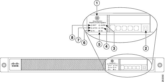
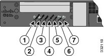
Figure 1 shows the front panel LEDs for the ASA 5512-X, ASA 5515-X, and ASA 5525-X models.
Figure 1 Front Panel LEDs for the Cisco ASA 5512-X, ASA 5515-X, and ASA 5525-X
|
|
|
|
|
|
A soft switch that turns the system on and off. Once pressed, the button stays in the “on” position: For information about the power state, see the Power Supply Considerations. |
|
|
|
||
|
|
– – |
|
|
|
||
|
|
||
|
|
||
|
|
||
|
|
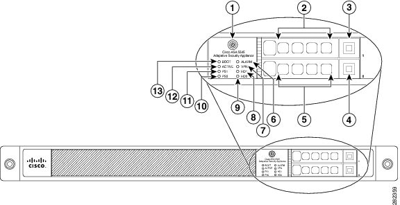
Figure 2 shows the front panel LEDs for the ASA 5545-X and ASA 5555-X models.
Figure 2 Front Panel LEDs for Cisco ASA 5545-X and ASA 5555-X
|
|
|
|
|
|
A soft switch that turns the system on and off. Once pressed, the button stays in the “on” position: For information about the power state, see Power Supply Considerations. |
|
|
|
||
|
|
||
|
|
||
|
|
||
|
|
– – |
|
|
|
||
|
|
||
|
|
||
|
|
||
|
|
Status of the primary power supply that ships with the product. |
|
|
|
||
|
|
Rear Panel LEDs
Figure 3 shows the rear panel LEDs for the ASA 5500-X.
Figure 3 Rear Panel LEDs for ASA 5500-X
Rear Panel Ports
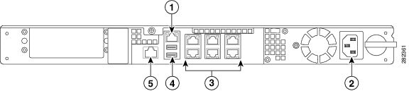
Figure 4 shows the ports for the ASA 5512-X and ASA 5515-X models.
Figure 4 Rear Panel Ports for the ASA 5512-X and ASA 5515-X
|
|
|
|
|
|
The GigabitEthernet interface that is restricted to management use only. Connect with an RJ-45 cable. |
|
|
|
||
|
|
The 6 on-board data interfaces. Connect with an RJ-45 cable. The top row port numbers are (from left to right) 5, 3, 1. The bottom row port numbers are (from left to right) 4, 2, 0. |
|
|
|
(See the Internal and External USB Flash Drives.) |
|
|
|
The RS-232 serial console port used to directly connect a computer to the ASA. Connect with an RJ-45 cable. |
Figure 5 shows the ports for the ASA 5525-X.
Figure 5 Rear Panel Ports for the ASA 5525-X
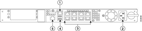
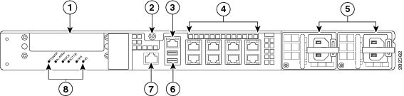
Figure 6 shows the rear panel ports for the ASA 5545-X and ASA 5555-X.
Figure 6 Rear Panel Ports for the ASA 5545-X and ASA 5555-X
|
|
|
|
|
|
Slot for the optional I/O Card. If you have a fiber-optic I/O card, use SFP modules to connect (not included). |
|
|
|
||
|
|
The GigabitEthernet interface that is restricted to management use only. Connect with an RJ-45 cable. |
|
|
|
The 8 on-board data interfaces. Connect with an RJ-45 cable. The top row port numbers are (from left to right) 7, 5, 3, 1. The bottom row port numbers are (from left to right) 6, 4, 2, 0. |
|
|
|
Slots for the primary power supply that ships with the device, and the optional redundant power supply. |
|
|
|
||
|
|
The RS-232 serial console port used to directly connect a computer to the ASA. Connect with an RJ-45 cable. |
|
|
|
Rear panel LEDs. (See Figure 3 for more information.) |
Power Supply
The ASA 5512-X, ASA 5515-X, and ASA 5525-X ship with one fixed fan and one fixed power supply (AC or DC) installed. The ASA 5545-X and ASA 5555-X ship with one power supply (AC or DC) installed.
- Dual Power Supply Support for the ASA 5545-X and ASA 5555-X
- Power On Guidelines
- AC and DC Support
- Power Supply Indicators and Connections
Dual Power Supply Support for the ASA 5545-X and ASA 5555-X
You can add an additional power supply, or you can order the ASA 5545-X or ASA 5555-X with two power supplies installed. Having two power supplies installed provides a redundant power option. This configuration ensures that if one power supply fails, the other power supply assumes the full load until the failed power supply is replaced.
To maintain air flow, an empty bay must be covered, or both bays must be populated with power supplies.
If only one power supply is installed, make sure that it is installed in slot 0 (left slot) and that slot 1 (right slot) is covered with a slot cover. If only one power supply is installed, do not remove the power supply unless the chassis has been powered off. Removing the only operational power supply causes an immediate power loss.
Power On Guidelines
The power supply is switched from Standby to ON by way of a system chassis STANDBY/ON switch. Earlier ASAs (V01) require you to turn on the power with the power switch. Newer ASAs (V02) automatically turn on when you plug in the power cable. To determine your version, do one of the following:
- At the CLI prompt, enter the show inventory command and look for V01 or V02 in the output.
- On the back of the chassis, look at the VID PID label for V01 or V02.
For the V01 chassis, see the following limitations:
- The ASA requires 50 seconds from the time that AC power is applied before the power state can be updated and stored. This means that any changes to the power state within the first 50 seconds of applying AC power will not be observed if AC power is removed within that time.
- The ASA requires 10 seconds from the time it is placed into standby mode before the power state can be updated and stored. This means any changes to the power state within the first 10 seconds of entering standby mode (including the standby mode itself) will not be observed if AC power is removed within that time.
For the V02 chassis, the above limitations to not apply.
The power supply slot numbers are on the back of the chassis to the left side of each power supply. When facing the back of the chassis, power supply slot 0 (PS0) is to the left and power supply slot 1(PS1) is to the right. By default, a single power supply is installed in slot 0.
AC and DC Support
The ASA supports the following power supplies:
- AC power supply—Provides 400 watt output power with two DC voltage outputs: +12 V and +5 V. The AC power supply operates between 85 and 264 VAC. The AC power supply current shares on the 12 V output and is used in a dual hot-pluggable configuration. The AC power supply consumes a maximum of 471 W of input power.
When the Cisco ASA 5500-X operates on AC power, it supports the ability to restore the previous power state of the system in the event that AC power is lost.
- DC power supply—Provides 400 watt output power with two DC voltage outputs: +12 V and +5.0 V. The power supply operates between –40.5 and –72 VDC. The DC power supply current shares on the 12 V output and is used in a dual hot-pluggable configuration. The DC power supply consumes a maximum of 500 W of input power.
Note![]() : The ASA 5545-X and ASA 5555-X can support two AC or two DC power supplies. Do not mix AC and DC power supply units in the same chassis.
: The ASA 5545-X and ASA 5555-X can support two AC or two DC power supplies. Do not mix AC and DC power supply units in the same chassis.
Power Supply Indicators and Connections
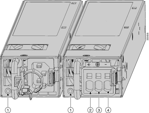
Figure 7 shows both the removable AC (on the left) and DC (on the right) power supplies for the ASA 5545-X and ASA 5555-X.
Figure 7 AC Power Supply and DC Power Supply
|
|
|
||
|
|
|
Table 1 describes the power supply indicator. The function of the indicator is the same for both the AC and DC power supplies.
Hardware Specifications
Table 2 contains hardware specifications for the ASA 5500-X series.
For additional specifications, see the product data sheet at the following URL:
http://www.cisco.com/c/en/us/products/collateral/security/asa-5500-x-series-next-generation-firewalls/data-sheet-c78-729807.html
Power Cord Specifications
Each power supply has a separate power cord. Standard power cords are available for connection to the security appliance.
If you do not order the optional power cord with the system, you are responsible for selecting the appropriate power cord for the product. Using a non-compatible power cord with this product may result in electrical safety hazard. Orders delivered to Argentina, Brazil, and Japan must have the appropriate power cord ordered with the system.
Only the approved power cords provided with the security appliance are supported. The following table lists the supported power cords.
|
|
|
|
|
|
|---|---|---|---|---|
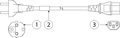
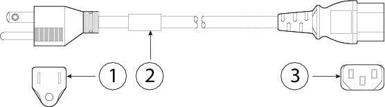
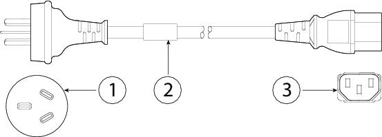
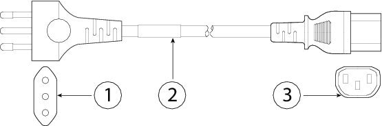
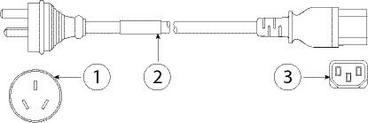
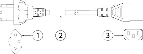
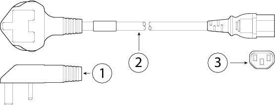
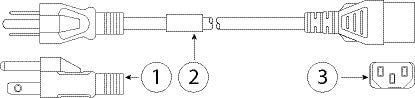
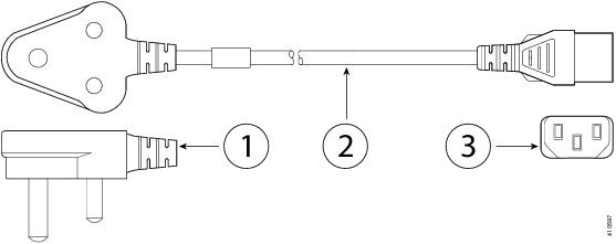
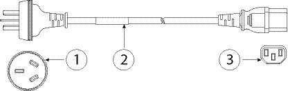
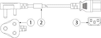
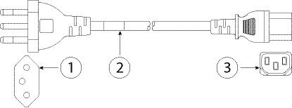
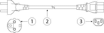
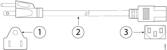
The following illustrations show the cord, connector, and plug for each country listed in Table 3 .
|
|
|
||
|
|
|
Figure 3-9 CAB-AC (North America)
|
|
|
||
|
|
|
Figure 3-10 CAB-ACA (Australia)
|
|
|
||
|
|
|
|
|
|
||
|
|
|
Figure 3-12 CAB-ACR (Argentina)
|
|
|
||
|
|
|
Figure 3-13 CAB-ACS (Switzerland)
|
|
|
||
|
|
|
Figure 3-14 CAB-ACU (United Kingdom)
|
|
|
||
|
|
|
Figure 3-15 CAB-JPN-3PIN (Japan)
|
|
|
||
|
|
|
Figure 3-16 AIR-PWR-CORD-SA (South Africa)
|
|
|
||
|
|
|
|
|
|
||
|
|
|
Figure 3-18 CAB-IND-10A (India)
|
|
|
||
|
|
|
Figure 3-19 CAB-C13-ACB (Brazil)
|
|
|
||
|
|
|
Figure 3-20 CAB-AC-C13-KOR (Korea)
|
|
|
||
|
|
|
|
|
|
||
|
|
|
 Feedback