Cisco 5915 Embedded Services Router Hardware Technical Guide
Available Languages
Table of Contents
Cisco 5915 Embedded Services Router Hardware Technical Guide
Cisco 5915 ESR Conduction-Cooled Card
Installing the Cisco 5915 ESR Conduction-Cooled Card
Removing the Cisco 5915 ESR Conduction-Cooled Card
Cisco 5915 ESR Air-Cooled Card
Cisco 5915 ESR LED Definitions
Important Notice about Zeroization
Temperature Out of Range Detection
Cisco 5915 ESR Conduction-Cooled Card Layout and Dimensions
Cisco 5915 Air-Cooled Card Layout and Dimensions
Cisco 5915 Embedded Services Router Hardware Technical Guide
Current Release:
February 18, 2021
This guide describes the Cisco 5915 Embedded Services Router (ESR) including product specifications, installation procedures, and hardware information.

Note![]() The documentation set for this product strives to use bias-free language. For purposes of this documentation set, bias-free is defined as language that does not imply discrimination based on age, disability, gender, racial identity, ethnic identity, sexual orientation, socioeconomic status, and intersectionality. Exceptions may be present in the documentation due to language that is hardcoded in the user interfaces of the product software, language used based on RFP documentation, or language that is used by a referenced third-party product.
The documentation set for this product strives to use bias-free language. For purposes of this documentation set, bias-free is defined as language that does not imply discrimination based on age, disability, gender, racial identity, ethnic identity, sexual orientation, socioeconomic status, and intersectionality. Exceptions may be present in the documentation due to language that is hardcoded in the user interfaces of the product software, language used based on RFP documentation, or language that is used by a referenced third-party product.
About This Guide
This guide is organized into the following sections:
–![]() Audience
Audience
–![]() Installing the Cisco 5915 ESR Conduction-Cooled Card
Installing the Cisco 5915 ESR Conduction-Cooled Card
–![]() Removing the Cisco 5915 ESR Conduction-Cooled Card
Removing the Cisco 5915 ESR Conduction-Cooled Card
- Cisco 5915 ESR Air-Cooled Card
- Cisco 5915 ESR LED Definitions
- Factory Default
- Temperature Out of Range Detection
- Using the Cisco 5915 ESR
- Product Specifications
- Hardware Information
–![]() Cisco 5915 ESR Conduction-Cooled Card Layout and Dimensions
Cisco 5915 ESR Conduction-Cooled Card Layout and Dimensions
–![]() Cisco 5915 Air-Cooled Card Layout and Dimensions
Cisco 5915 Air-Cooled Card Layout and Dimensions
Audience
This guide is for system integration engineers who are incorporating the Cisco 5915 ESR board into a chassis.
Related Documentation
Use these publications to help you configure Cisco IOS software features:
- The most current Cisco IOS configuration guides and command references are located at the following URL:
http://www.cisco.com/en/US/products/ps10148/products_installation_and_configuration_guides_list.html - For information about MIBs, refer to the following URL: http://tools.cisco.com/ITDIT/MIBS/servlet/index
Additional documentation for the Cisco 5900 ESR Series can be found at: www.cisco.com/go/5900
Conventions
This document uses the following typographical conventions:
Notes use the following conventions:

Note![]() Means reader take note. Notes contain helpful suggestions or references to material not covered in the publication.
Means reader take note. Notes contain helpful suggestions or references to material not covered in the publication.
Cautions use the following conventions:

Warnings use the following conventions:

Warning![]() Safety warnings appear throughout this publication in procedures that, if performed incorrectly, may cause harm to you or the equipment. A warning symbol precedes each warning statement.
Safety warnings appear throughout this publication in procedures that, if performed incorrectly, may cause harm to you or the equipment. A warning symbol precedes each warning statement.
Introduction
The Cisco 5900 Series Embedded Service Routers (ESR) are optimized for mobile and embedded networks that require IP routing and services. The flexible, compact form factors of the Cisco 5900 routers, complemented by Cisco IOS Software and Cisco Mobile Ready Net capabilities, provide highly secure data, voice, and video communications to stationary and mobile network nodes across wired and wireless links.
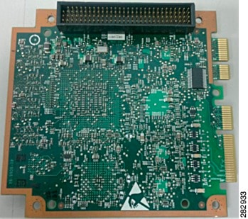
The Cisco 5915 ESR (Figure 1 and Figure 2) is a PCI-104 based, small form-factor router intended for mobile and vehicle networking applications. Like its predecessor Mobile Access Router Card, used in the Cisco 3200 Rugged Integrated Services Router (ISR), the Cisco 5915 ESR is targeted particularly at transportation customers (especially heavy, light, and metro rail) and global defense organizations.
The Cisco 5915 ESR is a high-performance router designed for harsh environments. Its highly durable construction provides reliable operation in extreme temperatures and in rugged terrain where mobile devices are often subject to greater degrees of shock and vibration. The inclusive and compact design simplifies integration and offers system integrators the ability to use the Cisco 5915 ESR in a wide variety of applications. The user interface for Cisco 5915 ESR is through edge fingers. Air-cooled and conduction-cooled models accommodate diverse operational environments. The Cisco 5915 ESR is based on industry standards, and provides Cisco customers with an extensive ecosystem of products and suppliers for designing and developing systems.
Figure 1 Cisco 5915 Embedded Services Router - Top Side View
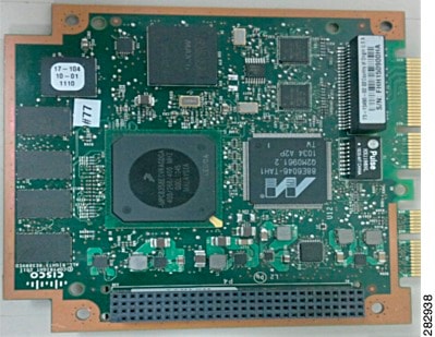
Figure 2 Cisco 5915 Embedded Services Router - Bottom Side View
Cisco 5915 ESR Conduction-Cooled Card
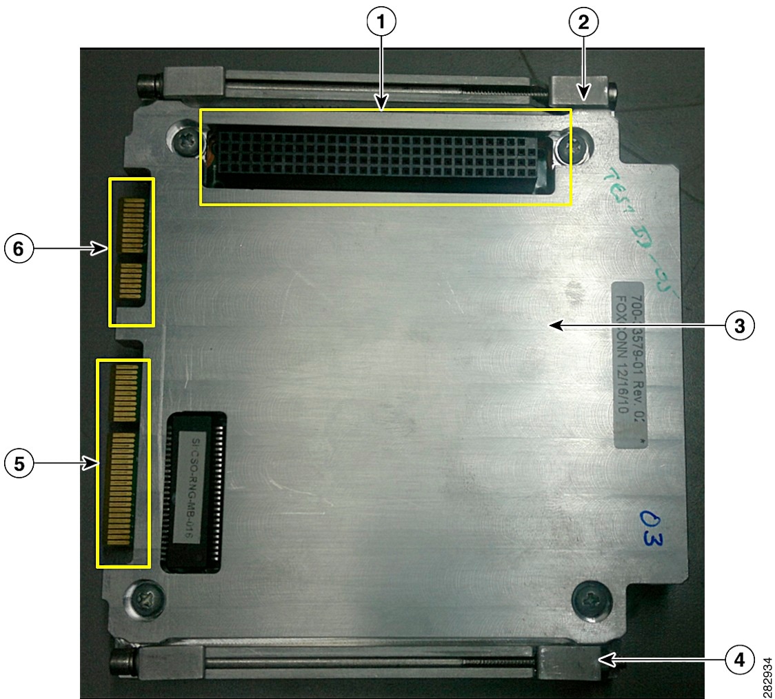
The Cisco 5915 ESR conduction-cooled card (Figure 3 and Figure 4) operates at a temperature range of -40ºC to +85ºC (rail temperature). Thermal plates conduct the heat away from the components to the enclosure rails through the wedge locks. The conduction cooling removes the need for internal fans.
Figure 3 Cisco 5915 ESR Conduction-Cooled Card - Bottom View
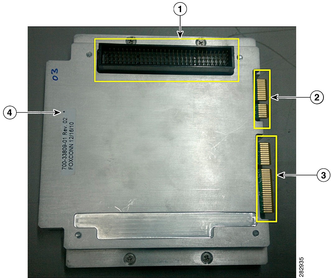
Figure 4 Cisco 5915 ESR Conduction-Cooled Card - Top View
Installing the Cisco 5915 ESR Conduction-Cooled Card

Warning![]() When performing the following procedures, wear a grounding wrist strap to avoid ESD damage to the Cisco 5915 ESR conduction-cooled card. Some platforms have an ESD connector for attaching the wrist strap. Do not directly touch the edge finger or PCI connector pins with your hand or any metal tool to avoid component failure.
When performing the following procedures, wear a grounding wrist strap to avoid ESD damage to the Cisco 5915 ESR conduction-cooled card. Some platforms have an ESD connector for attaching the wrist strap. Do not directly touch the edge finger or PCI connector pins with your hand or any metal tool to avoid component failure.
To install the Cisco 5915 ESR conduction-cooled card, perform the following procedure:
Step 1![]() Carefully align the edges of the thermal plate between the upper and lower edges of the module slot.
Carefully align the edges of the thermal plate between the upper and lower edges of the module slot.
Step 2![]() Verify that all the wedge locks are loose just enough to hold all the wedge lock pieces together.
Verify that all the wedge locks are loose just enough to hold all the wedge lock pieces together.
Step 3![]() Slide the card into the module slot.
Slide the card into the module slot.
Step 4![]() Tighten the wedge locks using a hex torque screwdriver adjusted to 8.0 +/- 0.5 in-lb.
Tighten the wedge locks using a hex torque screwdriver adjusted to 8.0 +/- 0.5 in-lb.

Removing the Cisco 5915 ESR Conduction-Cooled Card

Warning![]() When performing the following procedures, wear a grounding wrist strap to avoid ESD damage to the Cisco 5915 ESR conduction-cooled card. Some platforms have an ESD connector for attaching the wrist strap. Do not directly touch the edge finger or PCI connector pins with your hand or any metal tool to avoid component failure.
When performing the following procedures, wear a grounding wrist strap to avoid ESD damage to the Cisco 5915 ESR conduction-cooled card. Some platforms have an ESD connector for attaching the wrist strap. Do not directly touch the edge finger or PCI connector pins with your hand or any metal tool to avoid component failure.
To remove the Cisco 5915 ESR conduction-cooled card, use the following steps:
Step 1![]() Loosen the wedge locks using a hex screwdriver and complete seven (7) counter-clockwise turns.
Loosen the wedge locks using a hex screwdriver and complete seven (7) counter-clockwise turns.

Step 2![]() Carefully remove the Cisco 5915 ESR conduction-cooled card out of the conduction-cooled chassis.
Carefully remove the Cisco 5915 ESR conduction-cooled card out of the conduction-cooled chassis.
Cisco 5915 ESR Air-Cooled Card
The Cisco 5915 ESR air-cooled card operates at a temperature range of -40ºC to +70ºC. Forced air is used to cool the card.

Note![]() Cisco 5915 ESR air-cooled card installation depends on the system in which it will be used, hence the installation information does not fall under the scope of this document.
Cisco 5915 ESR air-cooled card installation depends on the system in which it will be used, hence the installation information does not fall under the scope of this document.
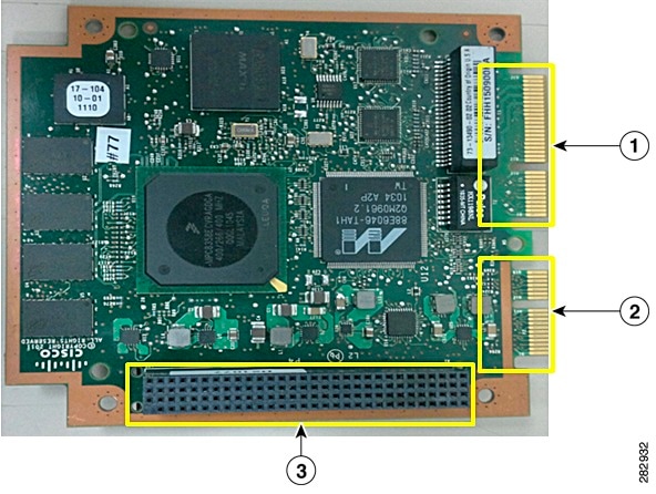
The Cisco 5915 ESR air-cooled board (Figure 5 and Figure 6) is used without thermal plates in an air-cooled environment. The minimum air-flow required depends on the installation environment. System integrators must perform the necessary thermal simulation to calculate the system level air-flow requirement.

Note![]() For more information about the Cisco 5915 ESR hot components and thermal limits refer to the Cisco 5915 ESR Thermal Data for Air-Cooled Cards Guide. To obtain the Cisco 5915 ESR Thermal Data for Air-Cooled Cards Guide, contact your Cisco account representative.
For more information about the Cisco 5915 ESR hot components and thermal limits refer to the Cisco 5915 ESR Thermal Data for Air-Cooled Cards Guide. To obtain the Cisco 5915 ESR Thermal Data for Air-Cooled Cards Guide, contact your Cisco account representative.
Figure 5 Cisco 5915 ESR Air-Cooled Card - Bottom View
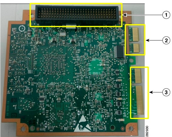
Figure 6 Cisco 5915 ESR Air-Cooled Card - Top View
Cisco 5915 ESR LED Definitions
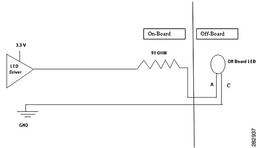
Cisco 5915 ESR supports the LED control signals described in Table 5 . These signals go to the edge fingers and connect to LEDs in the solution developed by a system integrator.
See Table 8 for pin location of LEDs on the edge finger interface.

Note![]() All LED outputs can drive 12mA through a 2.2Vf LED. All LED outputs are active high signals.
All LED outputs can drive 12mA through a 2.2Vf LED. All LED outputs are active high signals.
|
All Off-board LED signals are connected to the anode of the LED and the cathode of the LED is connected to ground (Figure 7).
Factory Default
To enable the factory default capability, the service declassify command must be added to the IOS configuration file. Following are the options available for this command:
Table 6 lists the settings and the completion time for these options.
This option erases the Flash file system that includes the IOS images and scrubs the main memory to ensure all code information is removed. |
6–25 minutes2 |
|
This option erases NVRAM and scrubs the main memory to ensure all code information is removed. |
||
This option is a superset of erase-flash and erase-nvram options. |
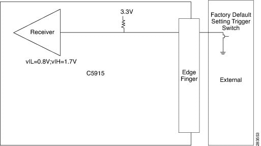
To start the Cisco 5915 ESR factory default process, pull the INPUT_CLEAR_L signal to GND (Figure 8). After the process is initiated, the LED_CLEAR signal toggles (blinks) for 0.5 seconds, then deasserts (turns off). After the process is completed, the LED_CLEAR signal asserts (turns on) and the router halts. Once the router is power-cycled, the router will boot normally. If you choose to use the erase-flash option, the boot process stops at ROMMON because the Flash file system that normally contains IOS is empty. If you choose to use the erase-all option, the Cisco 5915 ESR will have no user data or binary code in router memory after the factory default process is complete.
Figure 8 Factory Default Setting Trigger Implementation
eMMC is a managed NAND. This means that our embedded switch or router system does not interact with the flash memory directly. The flash controller presents a block-style interface to our system, and it handles the flash management (analogous to the Flash Translation Layer). Our embedded switch or router system cannot access the raw flash directly.
The JEDEC standard has commands that are supposed to remove data from the raw flash. In Cisco’s implementation, the “Erase” and “Sanitize” commands are used. The eMMC standard JESD84-B51 defines “Sanitize” as follows:
The Sanitize operation is a feature … that is used to remove data from the device according to Secure Removal Type. The use of the Sanitize operation requires the device to physically remove data from the unmapped user address space.
After the sanitize operation is completed, no data should exist in the unmapped host address space.

Note![]() Zeroization does NOT erase removable media such as SD Card and USB Storage. This media must be removed from the system and erased or destroyed using procedures that are outside the scope of this document.
Zeroization does NOT erase removable media such as SD Card and USB Storage. This media must be removed from the system and erased or destroyed using procedures that are outside the scope of this document.
Important Notice about Zeroization
Zeroize does a very thorough wipe of all non-protected parts of the eMMC flash using the best technology designed by the flash manufacturer today and can do so using the push of a button without the need for a console, ssh, or management session of any kind. It is the integrator's and end user's responsibility to determine the suitability regardless of the CLI keyword used to enable the feature.

Note![]() While Cisco IOS and Cisco IOS-XE use the command line text of “declassify” in the command line interface (CLI) to enable the zeroize feature, in no way does this represent any specific endorsement or acknowledgment of a Government approved flash erasure methodology.
While Cisco IOS and Cisco IOS-XE use the command line text of “declassify” in the command line interface (CLI) to enable the zeroize feature, in no way does this represent any specific endorsement or acknowledgment of a Government approved flash erasure methodology.
Declassification procedures are unique to each Government organization. Cisco solely provides the technical detail of the erasure operation here, not the policy distinction or any specific recommendation per classification.
Please refer to your respective Government Agency policies, procedures, and recommendations for the handling of sensitive data to see if this procedure meets with those requirements.
Temperature Out of Range Detection
When the Cisco 5915 ESR detects that the temperature is out of range, that is the temperature is either too high or too low, the router toggles (blinks) the LED_OVER_TEMP signal for 50 seconds. Assuming the temperature remains out of range during this period of time, the router deasserts (turns off) the LED_OVER_TEMP signal and reboots to ROMMON.
Using the Cisco 5915 ESR
The Cisco 5915 ESR can be deployed in a variety of applications and physical formats.
I/O signal access is provided via edge fingers. The edge fingers are intended to connect with standard, commercially available PCI-Express connectors.
Typically, integrators use a custom wiring board to access the I/O signals. For instance, one side of the wiring board is populated with the PCI-Express connectors, while the other side is populated with RJ-45s and/or circular shell connectors. This method works best when the enclosure is designed such that the end product I/O panel is very close to the edge finger side of the Cisco 5915 ESR.
Another I/O access option is to use a flex circuit assembly. A custom flex circuit assembly can be designed such that part of the assembly is rigid and part is more like a ribbon cable. The standard connectors (PCI-Express, RJ-45, circular shell, etc.) can be placed on the rigid parts of the assembly. This method provides a compact solution and is also useful when the end product I/O panel is not located close to the edge finger side of the Cisco 5915 ESR.
For integrators planning to use the conduction-cooled Cisco 5915 ESR, mounting holes are in the thermal plate. These mounting holes are used to hold an I/O board or flex circuit to the Cisco 5915 ESR. The mounting hole size is 0.125 Inches (diameter). Four 4-40 pan head screws are required.
For integrators planning to use the air cooled Cisco 5915 ESR, mounting holes are provided in the Printed Circuit Board (PCB) which can be used, along with a custom "L bracket" to hold an I/O board or flex circuit to the Cisco 5915 ESR.

Note![]() Mounting hole and screw sizes for air cooled Cisco 5915 ESR depend on the system or environment in which the air-cooled cards are used.
Mounting hole and screw sizes for air cooled Cisco 5915 ESR depend on the system or environment in which the air-cooled cards are used.

Note![]() When you connect routed ports of the Cisco 5915 ESR to routed ports on a neighboring device and autonegotiation is disabled on both sides of the connection, a crossover cable may be necessary (depending on the capabilities of the neighboring device). If autonegotiation is enabled, any type of cable connection can be used.
When you connect routed ports of the Cisco 5915 ESR to routed ports on a neighboring device and autonegotiation is disabled on both sides of the connection, a crossover cable may be necessary (depending on the capabilities of the neighboring device). If autonegotiation is enabled, any type of cable connection can be used.
Product Specifications
Table 7 lists the technical specifications for Cisco 5915 ESR.
One RS-232 console port supporting modem flow control signaling. |
|
–40° F to +185° F (–40° C to +85°C) component local ambient temperature ranges |
|

Note |
|

Note |
|
Mean Time Before Failure (MTBF)4 |
|
Hardware Information
This section shows layout of the Cisco 5915 ESR cards, pinout assignments, and other hardware specification information.
Cisco 5915 ESR Conduction-Cooled Card Layout and Dimensions
There is a zip file which contains graphics and.stp files available at:
https://www.cisco.com/c/dam/en/us/td/docs/solutions/GGSG-Engineering/Cisco_5915/Hardware_Install_Guide/SR5915-STEP.zip
The following figures show the layout and dimensions of the Cisco 5915 ESR conduction-cooled card. The dimensions are in inches.
Figure 9 Layout of the CIsco 5915 ESR Conduction-Cooled Card
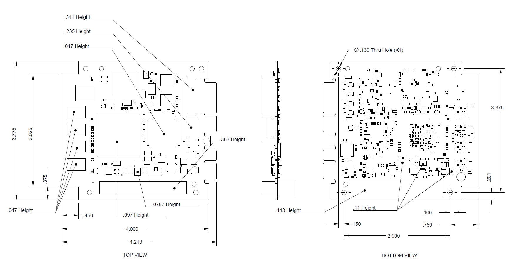
Cisco 5915 Air-Cooled Card Layout and Dimensions
Figure 10 shows the layout and dimensions of the Cisco 5915 ESR air-cooled card. The dimensions are in inches.
Figure 10 Layout of the Air-Cooled Card

Edge Fingers Interfaces
The Cisco 5915 ESR edge fingers provide system interface signal connectivity, while maximizing the real estate available for component placement. The connector solution is borrowed from the PCIe standard. The edge fingers consist of 64 pins in the main connector ( Table 8 ). The signal interfaces are routed through these pins. The following part numbers are the mating connectors (solderable):

Note![]() All signals on the Auxiliary edge fingers are reserved. Leave these signals unconnected.
All signals on the Auxiliary edge fingers are reserved. Leave these signals unconnected.
| ----------------------------------------------------notch------------------------------------------------------ |
||

Note![]() The FE0/0, FE0/1 are routed ports. FE0/2, FE0/3, and FE0/4 are switched ports.
The FE0/0, FE0/1 are routed ports. FE0/2, FE0/3, and FE0/4 are switched ports.
PCI Connector
The Cisco 5915 ESR is PCI-104 compliant and supports the standard PCI connector. Table 9 lists the pinout assignments. However, the Cisco 5915 ESR does not connect to the PCI bus because it is not used. The only electrical connections to the PCI connector are +5V, +3.3V, and GND.

Note![]() The Cisco 5915 ESR uses the variant of the PCI bus stacking connector, which is keyed on pin D30.
The Cisco 5915 ESR uses the variant of the PCI bus stacking connector, which is keyed on pin D30.

 Feedback