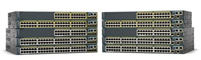
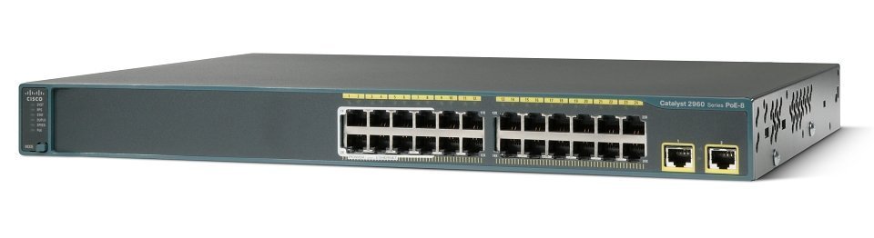
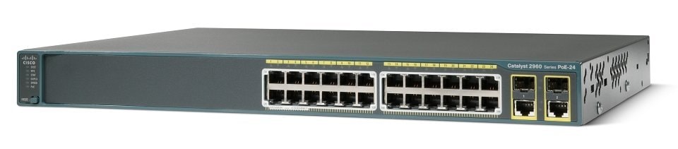
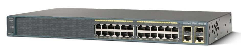
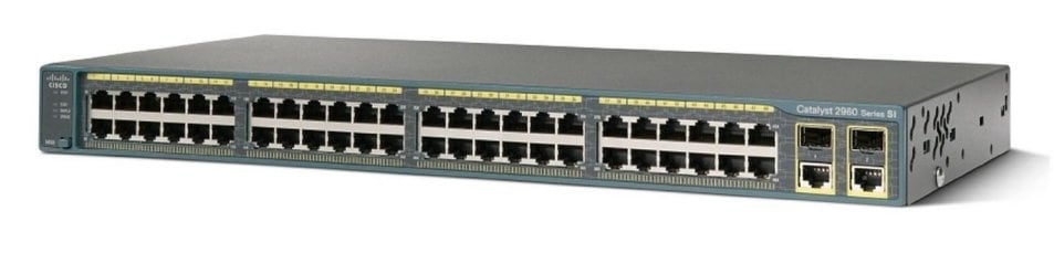
Configuring Flex Links


This chapter describes how to configure Flex Links, a pair of interfaces on the Catalyst 2960 switch that are used to provide a mutual backup.


Note For complete syntax and usage information for the commands used in this chapter, see the command reference for this release.


The chapter consists of these sections:

Understanding Flex Links

Configuring Flex Links

Monitoring Flex Links

Understanding Flex Links

Flex Links are a pair of a Layer 2 interfaces (switchports or port channels), where one interface is configured to act as a backup to the other. The feature provides an alternative solution to the Spanning Tree Protocol (STP), allowing users to turn off STP and still provide basic link redundancy. Flex Links are typically configured in service provider or enterprise networks where customers do not want to run STP on the switch. If the switch is running STP, it is not necessary to configure Flex Links because STP already provides link-level redundancy or backup.

You configure Flex Links on one Layer 2 interface (the active link) by assigning another Layer 2 interface as the Flex Link or backup link. When one of the links is up and forwarding traffic, the other link is in standby mode, ready to begin forwarding traffic if the other link shuts down. At any given time, only one of the interfaces is in the linkup state and forwarding traffic. If the primary link shuts down, the standby link starts forwarding traffic. When the active link comes back up, it goes into standby mode and does not forward traffic. STP is disabled on Flex Link interfaces.

In Figure 18-1, ports 1 and 2 on switch A are connected to uplink switches B and C. Because they are configured as Flex Links, only one of the interfaces is forwarding traffic; the other is in standby mode. If port 1 is the active link, it begins forwarding traffic between port 1 and switch B; the link between port 2 (the backup link) and switch C is not forwarding traffic. If port 1 goes down, port 2 comes up and starts forwarding traffic to switch C. When port 1 comes back up, it goes into standby mode and does not forward traffic; port 2 continues forwarding traffic.

Figure 18-1 Flex Links Configuration Example

If a primary (forwarding) link goes down, a trap notifies the network management stations. If the standby link goes down, a trap notifies the users.

Flex Links are supported only on Layer 2 ports and port channels, not on VLANs.

Configuring Flex Links

These sections contain this configuration information:

Default Flex Link Configuration

Flex Link Configuration Guidelines

Configuring Flex Links

Default Flex Link Configuration

By default, Flex Links are not configured, and there are no backup interfaces defined.

Flex Link Configuration Guidelines

Follow these guidelines to configure Flex Links:

You can configure only one Flex Link backup link for any active link, and it must be a different interface from the active interface.

An interface can belong to only one Flex Link pair. An interface can be a backup link for only one active link. An active link cannot belong to another Flex Link pair.

Neither of the links can be a port that belongs to an EtherChannel. However, you can configure two port channels (EtherChannel logical interfaces) as Flex Links, and you can configure a port channel and a physical interface as Flex Links, with either the port channel or the physical interface as the active link.

A backup link does not have to be the same type (Fast Ethernet, Gigabit Ethernet, or port channel) as the active link. However, you should configure both Flex Links with similar characteristics so that there are no loops or changes in behavior if the standby link begins to forward traffic.

STP is disabled on Flex Link ports. If STP is configured on the switch, Flex Links do not participate in STP in all VLANs in which STP is configured. With STP not running, be sure that there are no loops in the configured topology.

Configuring Flex Links

Beginning in privileged EXEC mode, follow these steps to configure a pair of Flex Links:

 
Command
Purpose

Step 1 

configure terminal

Enter global configuration mode.

Step 2 

interface interface-id

Specify the interface, and enter interface configuration mode. The interface can be a physical Layer 2 interface or a port channel (logical interface). The port-channel range is 1 to 6.

Step 3 

switchport backup interface interface-id

Configure a physical Layer 2 interface (or port channel) as part of a Flex Link pair with the interface. When one link is forwarding traffic, the other interface is in standby mode.

Step 4 

end

Return to privileged EXEC mode.

Step 5 

show interface [interface-id] switchport backup

Verify the configuration.

Step 6 

copy running-config startup config

(Optional) Save your entries in the switch startup configuration file.

This example shows how to configure an interface with a backup interface and to verify the configuration:

Switch# configure terminal 
Switch(conf)# interface fastethernet0/1
Switch(conf-if)# switchport backup interface fastethernet0/2
Switch(conf-if)# end
Switch# show interface switchport backup
Switch Backup Interface Pairs:

Active Interface        Backup Interface        State
------------------------------------------------------------------------------------------
FastEthernet0/1         FastEthernet0/2         Active Up/Backup Standby
FastEthernet0/3         FastEthernet0/4         Active Up/Backup Standby
Port-channel1           GigabitEthernet0/1      Active Up/Backup Standby

Monitoring Flex Links

Table 18-1 shows the privileged EXEC command for monitoring Flex Link configuration.

Table 18-1 Flex Link Monitoring Command

Command
Purpose

show interface [interface-id] switchport backup

Displays the Flex Link backup interface configured for an interface, or displays all Flex Links configured on the switch and the state of each active and backup interface (up or standby mode).