Product Overview
The Catalyst 3560-C and 2960-C of switches, also referred to as the switch, are Ethernet switches to which you can connect devices such as Cisco IP Phones, Cisco Wireless Access Points, workstations, and other network devices such as servers, routers, and other switches.
You can deploy these switches outside of the traditional wiring closet environment, such as in office workspaces, hotel rooms, slot machines, kiosks, and classrooms. The switch is suitable for deployments where there are space and power constraints (access to power outlets).
See the switch software configuration guide for deployment examples.
Switch Models
|
|
|
|---|---|
Catalyst 2960CPD-8TT-L |
8 10/100 Ethernet ports and 2 10/100/1000BASE-T PD uplink copper ports. |
Catalyst 2960CPD-8PT-L |
8 10/100 PoE1 ports and 2 10/100/1000BASE-T PD uplink copper ports. |
Catalyst 2960CG-8TC-L |
8 10/100/1000 Ethernet ports and 2 dual-purpose ports (1 10/100/1000BASE-T copper port and |
Catalyst 2960C-8TC-L |
8 10/100 Ethernet ports and 2 dual-purpose ports. |
Catalyst 2960C-8TC-S |
8 10/100 Ethernet ports and 2 dual-purpose ports. |
Catalyst 2960C-8PC-L |
8 10/100 PoE ports and 2 dual-purpose ports. |
Catalyst 2960C-12PC-L |
12 10/100 PoE ports and 2 dual-purpose ports. |
Catalyst 3560CG-8PC-S |
8 10/100/1000 PoE+ ports and 2 dual-purpose ports. |
Catalyst 3560CG-8TC-S |
8 10/100/1000 Ethernet ports and 2 dual-purpose ports. |
Catalyst 3560CPD-8PT-S |
8 10/100/1000 PoE ports and 2 10/100/1000BASE-T PD uplink copper ports. |
Catalyst 3560C-8PC-S |
8 10/100 PoE+ ports and 2 dual-purpose ports. |
Catalyst 3560C-12PC-S |
12 10/100 PoE+ ports and 2 dual-purpose ports. |
1 PoE = Power over Ethernet 2 SFP = small form-factor pluggable |
Front Panel
•![]() 8 or 12 downlink Ethernet ports of one of these types:
8 or 12 downlink Ethernet ports of one of these types:
–![]() 10/100
10/100
–![]() 10/100/1000
10/100/1000
–![]() 10/100 PoE
10/100 PoE
–![]() 10/100 PoE+
10/100 PoE+
–![]() 10/100/1000 PoE
10/100/1000 PoE
–![]() 10/100/1000 PoE+
10/100/1000 PoE+
•![]() Two 10/100/1000 uplink ports or two dual purpose ports
Two 10/100/1000 uplink ports or two dual purpose ports
•![]() RJ-45 console port
RJ-45 console port
•![]() USB mini-Type B (console) port
USB mini-Type B (console) port
•![]() USB Type A port (available on the Catalyst 3560CPD-8PT-S, 2960CG-8TC-L, 3560CG-8PC-S, and 3560CG-8TC-S switches)
USB Type A port (available on the Catalyst 3560CPD-8PT-S, 2960CG-8TC-L, 3560CG-8PC-S, and 3560CG-8TC-S switches)
•![]() LEDs
LEDs
All the 8-port and 12-port switches have similar components. See Figure 1-1, Figure 1-2, Figure 1-3, Figure 1-4, and Figure 1-5 for examples.
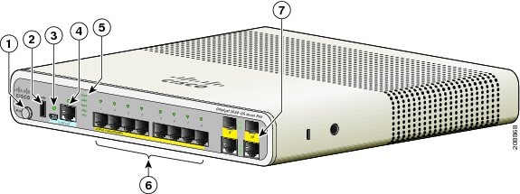
Figure 1-1 Catalyst 2960CPD-8PT-L Front Panel View

|
|
Mode button |
|
LEDs |
|
|
USB mini-Type B (console) port |
|
10/100 PoE ports |
|
|
RJ-45 console port |
|
10/100/1000 uplink ports |
Figure 1-2 Catalyst 3560CG-8PC-S Front Panel View
|
|
Mode button |
|
LEDs |
|
|
USB Type A port |
|
10/100/1000 PoE+ ports |
|
|
USB mini-Type B (console) port |
|
Dual-purpose ports |
|
|
RJ-45 console port |
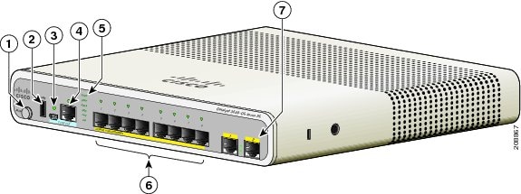
Figure 1-3 Catalyst 3560CPD-8PT-S Front Panel View
|
|
Mode button |
|
LEDs |
|
|
USB Type A port |
|
10/100/1000 PoE ports |
|
|
USB mini-Type B (console) port |
|
10/100/1000 uplink ports |
|
|
RJ-45 console port |
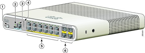
Figure 1-4 Catalyst 2960C-12PC-L Front Panel View
|
|
Mode button |
|
LEDs |
|
|
USB mini-Type B (console) port |
|
10/100 PoE ports |
|
|
RJ-45 console port |
|
Dual-purpose ports |
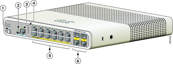
Figure 1-5 Catalyst 3560C-12PC-S Front Panel View
|
|
Mode button |
|
LEDs |
|
|
USB mini-Type B (console) port |
|
10/100 PoE ports |
|
|
RJ-45 console port |
|
Dual-purpose ports |
10/100 and 10/100/1000 Fast Ethernet Downlink Ports
You can set the 10/100 ports to operate at 10 or 100 Mb/s in full-duplex or half-duplex mode. You can set the 10/100/1000 ports to operate at 10, 100, or 1000 Mb/s in full-duplex or half-duplex mode. You can also set these ports for speed and duplex autonegotiation. (The default setting is autonegotiate.)
Automatic medium-dependent interface crossover (auto-MDIX) is a feature that allows the switch interface to detect the required cable connection type (straight-through or crossover) and automatically configure the connection appropriately. With auto-MDIX enabled, you can use either a straight-through or crossover type cable to connect to the other device, and the interface automatically corrects for any incorrect cabling. In all cases, the attached device must be within 328 feet (100 meters)
The 10/100/1000 ports use RJ-45 connectors with Ethernet pinouts. The maximum cable length is
328 feet (100 meters). The 100BASE-TX and 1000BASE-T traffic requires Category 5, Category 5e, or Category 6 unshielded twisted pair (UTP) cable. The 10BASE-T traffic can use Category 3 or
Category 4 UTP cable.
For information about port connections and port specifications, see the "Connecting to the 10/100 and 10/100/1000 Ports" section.
PoE Ports (Switches with PoE Ports)
The PoE and PoE+ ports provide PoE support for devices compliant with 802.3af and 802.3at and also provide Cisco prestandard PoE and PoE+ support for Cisco IP Phones and Cisco Aironet Access Points.
All 8 downlink ports on the Catalyst 2960CPD-8PT-L, 2960C-8PC-L, 2960C-12-PC-L, and the 3560CPD-8PT-S and are PoE-capable. Each port can supply 15.4 W of PoE per port.
The maximum switch power output for the Catalyst 2960CPD-8PT-L is 22.4 W, and for the
Catalyst 3560CPD-8PT-S is 15.4 W. The maximum switch power output for the Catalyst 2960C-8PC-L and the 2960C-12-PC-L is 123.2 W.
All 8 or 12 downlink ports on the Catalyst,3560CG-8PC-S, 3560C-8PC-S, and 3560C-12PC-S switches are PoE+ capable. The maximum switch power output is 123.2 W. You can budget the PoE and PoE+:
•![]() 15.4 W of PoE output on eight ports
15.4 W of PoE output on eight ports
•![]() 30 W of PoE+ on four ports
30 W of PoE+ on four ports
On a per-port basis, you control whether or not a port automatically provides power when an IP phone or an access point is connected.
The 10/100/1000 PoE ports use RJ-45 connectors with Ethernet pinouts. The maximum cable length is 328 feet (100 meters). The 100BASE-TX and 1000BASE-T traffic requires Category 5, Category 5e, or Category 6 unshielded twisted pair (UTP) cable. The 10BASE-T traffic can use Category 3 or
Category 4 UTP cable.
Cisco intelligent power management capabilities include enhanced power negotiation, power reservation, and per-port power policing. For information about configuring and monitoring PoE ports, see the switch software configuration guide on Cisco.com.
For information about port connections and port specifications, see the "Connecting to the 10/100 and 10/100/1000 Ports" section.

Note ![]() The output of the PoE circuit has been evaluated as a Limited Power Source (LPS) per IEC 60950-1.
The output of the PoE circuit has been evaluated as a Limited Power Source (LPS) per IEC 60950-1.
PoE Pass-Through
The Catalyst 2960CPD-8PT-L and 3560CPD-8PT-S switches provide PoE pass-through. The
Catalyst 2960CPD-8PT-L is powered either through the 10/100/1000 PoE uplink ports receiving power from a PoE or PoE+ switch or through an auxiliary power adapter. The Catalyst 3560CPD-8PT-S is powered through the 10/100/1000 PoE uplink ports receiving power from a PoE+ switch or through an auxiliary power adapter. If the switch has surplus power (see Table 1-2), it can power other PoE-capable devices such as IP phones, access points, and so on. See Figure 1-6.
See the "Powering the Switch" section for information on powering the switches.
Figure 1-6 PoE Pass-Through

The available switch PoE budget depends upon the PoE sent from the uplink switch. See Table 1-2.
|
Uplink Ports |
|
|
|---|---|---|
1 PoE uplink |
15.4 W |
- |
2 PoE uplinks |
30.8 W |
7 W |
1 PoE+ uplink |
30 W |
7 W |
2 PoE+ uplinks |
60 W |
22.4 W |
1 PoE and 1 PoE+ uplink |
45.4 W |
15.4 W |
I Cisco UPOE uplink |
60 W |
30.8 W1 |
2 Cisco UPOE uplinks |
120 W |
30.8 W1 |
Auxiliary power input |
- |
22.4 W (30.82 ) |
1 The second UPOE uplink is a backup. 2 When the Auxiliary AC input is used as a backup to a Cisco UPOE powered switch. |
|
Uplink Ports |
|
|
|---|---|---|
1 PoE+ uplink |
30 W |
- |
2 PoE+ uplinks |
60 W |
15.4 W |
1 Cisco UPOE uplink |
60 W |
23.8 W1 |
2 Cisco UPOE uplinks |
120 W |
23.8 W1 |
Auxiliary power input |
- |
15.4 W (23.8 W2 ) |
1 The second UPOE uplink is a backup. 2 When the Auxiliary AC input is used as a backup to a Cisco UPOE powered switch. |
PoE Uplink Ports (Catalyst 2960CPD-8TT-L, 2960CPD-8PT-L, and 3560CPD-8PT-S)
The 10/100/1000 PoE uplink ports on the Catalyst 2960CPD-8TT-L and 2960CPD-8PT-L can receive power from a PoE or PoE+ switch. The 10/100/1000 PoE uplink ports on the Catalyst 3560CPD-8PT-S can receive power from a PoE+ switch. You can connect each of the uplink ports to different PoE switches or to the same PoE switch. See Figure 1-6.
Note ![]() You can also use an external auxiliary power adapter that connects to the rear of the switch. You can order it from your Cisco representative. See the "Auxiliary Power Adapter" section for information.
You can also use an external auxiliary power adapter that connects to the rear of the switch. You can order it from your Cisco representative. See the "Auxiliary Power Adapter" section for information.
PoE-Capable Downlink Ports (Catalyst 2960CPD-8PT-L, 3560CG-8PC-S, 3560CPD-8PT-S, 2960C-8PC-L, 2960C-12PC-L, 3560C-8PC-S, and 3560C-12PC-S)
Depending upon the available PoE budget, these switches can power other PoE-capable devices such as IP phones, access points, and so on. See Table 1-2 for PoE budgeting information. See Figure 1-6.
For information on powering the switches, see the "Powering the Switch" section.
USB Type A Port
Some models have an USB Type A port. This port provides access to external Cisco USB flash devices (also known as thumb drives or USB keys). The port supports Cisco USB flash drives with capacities from 64 MB to 1 GB.
Cisco IOS software provides standard file system access to the flash device: read, write, erase, and copy, as well as the capability to format the flash device with a FAT file system.
For more information about the switch management ports, see the switch software configuration guide and the command reference on Cisco.com.
Dual-Purpose Ports
You can configure the dual-purpose ports on the switch as either 10/100/1000 ports or as SFP-module ports. You can set the 10/100/1000 ports to autonegotiate, or you can configure them as fixed 10, 100, or 1000 Mb/s (Gigabit) Ethernet ports.
By default, the switch selects the medium for each dual-purpose port (10/100/1000BASE-T or SFP). When a link is achieved on one media type, the switch disables the other media type until the active link goes down. If links are active on both media, the SFP-module port has priority, but you can use the media-type interface configuration command to manually designate the port as an RJ-45 port or an SFP port.
You can configure the speed and duplex settings consistent with the selected media type. For information on configuring interfaces, see the switch software configuration guide.
SFP Modules
The switch Ethernet SFP modules provide connections to other devices. These field-replaceable transceiver modules provide the uplink interfaces.The modules have LC connectors for fiber-optic connections or RJ-45 connectors for copper connections.
You can use any combination of these supported SFP modules:
•![]() GLC-LH-SM=
GLC-LH-SM=
•![]() GLC-SX-MM=
GLC-SX-MM=
•![]() GLC-ZX-SM=
GLC-ZX-SM=
•![]() GLC-BX-D=
GLC-BX-D=
•![]() GLC-BX-U=
GLC-BX-U=
•![]() GLC-FE-100FX=
GLC-FE-100FX=
•![]() GLC-FE-100LX=
GLC-FE-100LX=
•![]() GLC-FE-100BX-D=
GLC-FE-100BX-D=
•![]() GLC-FE-100BX-U=
GLC-FE-100BX-U=
•![]() CWDM SFPs
CWDM SFPs
For information about SFP modules, see your SFP module documentation and the "Installing SFP Modules" section. For cable specifications, see the "SFP Module Cables" section on page B-3.
Management Ports
You can connect the switch to a PC running Microsoft Windows or to a terminal server through either the RJ-45 console port or the USB mini-Type B console port, also referred to as the USB-mini console port.
•![]() RJ-45 console port. The RJ-45 connection uses an RJ-45-to-DB-9 female cable.
RJ-45 console port. The RJ-45 connection uses an RJ-45-to-DB-9 female cable.
•![]() USB-mini console port (5-pin connector). The USB connection uses a USB Type A-to-5-pin mini-Type B cable.
USB-mini console port (5-pin connector). The USB connection uses a USB Type A-to-5-pin mini-Type B cable.
The USB-mini console interface speeds are the same as the RJ-45 console interface speeds.
To use the USB-mini console port, you must install the Cisco Windows USB device driver on the device that is connected to the USB-mini console port and that is running Microsoft Windows.
Note ![]() For information about downloading the Cisco USB device driver, see the "Installing the Cisco Microsoft Windows USB Device Drivers" section.
For information about downloading the Cisco USB device driver, see the "Installing the Cisco Microsoft Windows USB Device Drivers" section.
With the Cisco Windows USB device driver, connecting and disconnecting the USB cable from the console port does not affect Windows HyperTerminal operations. Mac OS X or Linux require no special drivers.
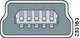
Note ![]() The 5-pin mini-Type B connectors resemble the 4-pin mini-Type B connectors. They are not compatible. Use only the 5-pin mini-Type B. See Figure 1-7.
The 5-pin mini-Type B connectors resemble the 4-pin mini-Type B connectors. They are not compatible. Use only the 5-pin mini-Type B. See Figure 1-7.
Figure 1-7 USB Mini-Type B Port
The configurable inactivity timeout reactivates the RJ-45 console port if the USB-mini console port is activated, but no input activity occurs for a specified time period. When the USB-mini console port deactivates due to a timeout, you can restore its operation by disconnecting and reconnecting the USB cable. For information on using the CLI to configure the USB-mini console interface, see the switch software guide.
LEDs
You can use the switch system and port LEDs to monitor switch activity and performance.
Switch Panel LEDs
Figure 1-8 Switch LEDs

|
|
Mode button |
|
SPD LED (speed) |
|
|
SYST LED (system) |
|
PoE LED1 |
|
|
STAT LED (status) |
|
PD LED2 (powered device) |
|
|
DPLX LED (duplex) |
|
Port LEDs |
1 Applicable to switches with PoE ports. 2 Only the Catalyst 2960CPD-8PT-L and 3560PD-8PT-S switches have the PD LED. |
System LED
|
|
|
|---|---|
Off |
System is not powered on. |
Green |
System is operating normally. |
Amber |
System is receiving power but is not operating properly. |
Console LEDs
The console LEDs show which console port is in use. See Figure 1-1 and Figure 1-2 for the LED locations.
If you connect a cable to a console port, the switch automatically uses that port for console communication. If you connect two console cables, the USB-mini console port has priority.
Modes for Port LEDs
The port LEDs, as a group or individually, display information about the switch and about the individual ports (Table 1-5).
|
|
|
|
|---|---|---|
STAT |
Port status |
The port status. This is the default mode. |
DUPLX |
Port duplex status |
The port duplex mode: full duplex or half duplex. |
SPD |
Port speed |
The port operating speed: 10, 100, or 1000 Mb/s. |
PD 1 |
Powered device |
The status of the uplink port. |
PoE |
PoE port power |
The PoE status. |
1 Only the Catalyst 2960CPD-8PT-L and 3560PD-8PT-S switches have the PD LED. |
Port LEDs
RJ-45 ports and SFP-module slots have port LEDs. These LEDs, as a group or individually, provide information about the switch and about the individual ports.
PoE LED
Even if the PoE mode is not selected, the LED shows PoE problems when they are detected (Table 1-8). The PoE LED is only on the switches that support PoE.
PD LED
Applies only to the Catalyst 2960CPD-8PT-L and 3560PD-8PT-S switches. (Table 1-9).
Dual-Purpose Port LEDs
The dual-purpose port LEDs identify the connection as either a copper-based connector or an SFP module. The ports can autonegotiate, or you can manually configure each dual-purpose port as either 10/100/1000 with copper connectors or as an SFP-module port, but not as both types at the same time. See Table 1-7 for LED descriptions.
Figure 1-9 Dual-Purpose LEDs

|
|
SFP module port LED |
|
RJ-45 port LED |
|
|
SFP module port LED |
|
RJ-45 port LED |
|
|
SFP module slot |
|
RJ-45 connector |
|
|
RJ-45 connector |
|
SFP module slot |
Rear Panel
•![]() A reset button
A reset button
•![]() A security slot
A security slot
•![]() An AC power connector or a power adapter connector
An AC power connector or a power adapter connector
•![]() Heat sink fins (Catalyst 3560CG-8PC-S, 2960C-8PC-L, 2960C-12PC-L, 3560C-8PC-S, and 3560C-12PC-S switches)
Heat sink fins (Catalyst 3560CG-8PC-S, 2960C-8PC-L, 2960C-12PC-L, 3560C-8PC-S, and 3560C-12PC-S switches)
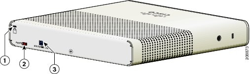
Figure 1-10 Catalyst 2960CPD-8PT-L Switch Rear Panel
|
|
Security slot |
|
Power adapter connector |
|
|
Reset button |
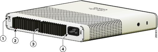
Figure 1-11 Catalyst 3560CG-8PC-S Switch Rear Panel
|
|
Security slot |
|
Heat sink fins |
|
|
Reset button |
|
AC power connector |
Internal Power Supply
All switches except the Catalyst 2960CPD-8TT-L, 2960CPD-8PT-L, and 3560CPD-8PT-S are powered through their internal power supplies. The internal power supply is an autoranging unit that supports input voltages between 100 and 240 VAC. Plug the AC power cord into the AC power connector and into an AC power outlet.
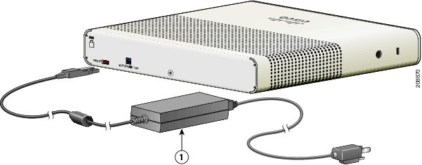
Auxiliary Power Adapter
The Catalyst 2960CPD-8TT-L, 2960CPD-8PT-L, and 3560CPD-8PT-S switches do not have a internal power supply. You can power the switch through either the 10/100/1000 uplink ports or through an auxiliary power adapter. You can order the auxiliary power adapter (PWR-ADPT) with the switch, or you can order it (PWR-ADPT=) later from your Cisco representative.
Figure 1-12 Connecting Through an External Auxiliary Power Adapter
|
|
Auxiliary power adapter |
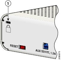
Security Slots
The switches have security slots on the rear panel. You can install an optional cable lock, such as the type that is used to secure a laptop computer, to secure the switch.
Figure 1-13 shows the slot on a rear panel.
Figure 1-13 Switch Left Panel
|
|
Security slot |
Reset Button
You can use press the reset button to power-cycle the switch. See Figure 1-13.
Management Options
•![]() Cisco Network Assistant
Cisco Network Assistant
Network Assistant is a PC-based network management GUI with centralized management of
Cisco LAN switches, core switches, routers, access points, IP phones, and PIX firewalls.
Network Assistant is available at no cost and can be downloaded from this URL:
http://www.cisco.com/en/US/products/ps5931/tsd_products_support_series_home.html
For information on starting Network Assistant, see the Getting Started with Cisco Network Assistant guide on Cisco.com. See the switch release notes for information on CNA support.
•![]() Device manager
Device manager
You can use the device manager, which is in the switch memory, to manage individual and standalone switches. Device manager is a web interface that offers quick configuration and monitoring. You can access the device manager from anywhere in your network through a web browser. For more information, see the device manager online help.
•![]() Cisco IOS CLI
Cisco IOS CLI
The switch CLI is based on Cisco IOS software and supports desktop-switching features. You can configure and monitor the switch and switch cluster members from the CLI. You can access the CLI either by connecting your management station directly to the switch console port or by using Telnet from a remote management station. See the switch command reference on Cisco.com for more information.
For setup instructions that use the CLI, go to "Configuring the Switch with the CLI Setup Program."
•![]() CiscoView application
CiscoView application
The CiscoView device-management application displays the switch image that you can use to set configuration parameters and to view switch status and performance information. The CiscoView application, which you purchase separately, can be a standalone application or part of a Simple Network Management Protocol (SNMP) platform. See the CiscoView documentation for more information.
•![]() SNMP network management
SNMP network management
You can use SNMP management applications such as CiscoWorks LAN Management Solution (LMS) and HP OpenView to configure and manage the switch. You also can manage it from an SNMP-compatible workstation that is running platforms such as HP OpenView or SunNet Manager.
The Cisco Configuration Engine is a network management device that works with embedded CNS agents in the switch software. You can use the Cisco Configuration Engine to automate initial configurations and configuration updates on the switch.
Network Configurations
See the switch software configuration guide on Cisco.com for an explanation of network configuration concepts. The software configuration guide also provides network configuration examples for creating dedicated network segments that are interconnected through Ethernet connections.
 Feedback