Catalyst 3750 Switch Getting Started Guide
Available Languages
Table Of Contents
Catalyst 3750 Switch Getting Started Guide
Equipment That You Supply to Run Express Setup
Downloading Cisco Network Assistant
Installation Warning Statements
Connect to 10/100 and 10/100/1000 Ports
Install the SFP Modules and Connect to the Ports
Install the XENPAK Module and Connect to the Ports
Obtaining Documentation, Obtaining Support, and Security Guidelines
Getting Started Guide
Catalyst 3750 Switch Getting Started Guide
1 About this Guide
This guide provides instructions on how to use Express Setup to initially configure your Catalyst switch. Also covered are switch management options, basic rack-mounting procedures, stacking procedures, port and module connection procedures, power connection procedures, and troubleshooting help.
For additional installation and configuration information for Catalyst 3750 switches, see the Catalyst 3750 documentation on Cisco.com. For system requirements, important notes, limitations, open and resolved bugs, and last-minute documentation updates, see the release notes, also on Cisco.com.
When using the online publications, refer to the documents that match the Cisco IOS software version running on the switch. The software version is on the Cisco IOS label on the switch rear panel.
For translations of the warnings that appear in this publication, see the Regulatory Compliance and Safety Information for the Catalyst 3750 Switch that accompanies this guide.
2 Taking Out What You Need
Follow these steps:
1.
Unpack and remove the switch and the accessory kit from the shipping box.
2.
Return the packing material to the shipping container, and save it for future use.
3.
Verify that you have received the items shown on page 3. If any item is missing or damaged, contact your Cisco representative or reseller for instructions. Some switch models might include additional items that are not shown on page 3.

Note
If you do not specify the length of the StackWise cable, the 0.5-meter cable is supplied.
Equipment That You Supply to Run Express Setup
You need to supply this equipment to run Express Setup:
•
PC
•
Ethernet (Category 5) straight-through cable (as shown)

Shipping Box Contents

3 Running Express Setup
When you first set up the switch, you should use Express Setup to enter the initial IP information. This enables the switch to connect to local routers and the Internet. You can then access the switch through the IP address for further configuration.
To run Express Setup:
Step 1
Make sure that nothing is connected to the switch.
During Express Setup, the switch acts as a DHCP server. If your PC has a static IP address, change your PC settings before you begin to temporarily use DHCP.
Step 2
Power the switch by connecting the supplied AC power cord to the switch power connector and to a grounded AC outlet.
Step 3
When the switch powers on, it begins the power-on self-test (POST). During POST, the LEDs blink while tests verify that the switch functions properly.
Wait for the switch to complete POST, which can take several minutes.
Step 4
Verify that POST has completed by confirming that the SYST LED remains green. If the switch fails POST, the SYST LED turns amber.
POST errors are usually fatal. Contact your Cisco technical support representative if your switch fails POST.
Step 5
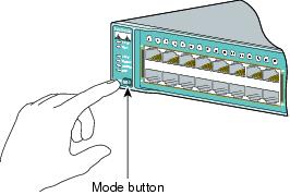
Press and hold the Mode button for 3 seconds. When all of the LEDs left of the Mode button turn green, release the Mode button.
If the LEDs left of the Mode button begin to blink after you press the button, release it. Blinking LEDs mean that the switch has already been configured and cannot go into Express Setup mode. For more information, see the "Resetting the Switch" section.

Step 6
Verify that the switch is in Express Setup mode by confirming that all LEDs left of the Mode button are green. (On some models, the RPS and PoE LEDs remain off.)
Step 7
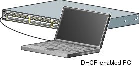
Connect a Category 5 Ethernet cable to any 10/100 or 10/100/1000 Ethernet port on the switch front panel.
Connect the other end of the cable to the Ethernet port on your PC.

Step 8
Verify that the switch and PC Ethernet ports LEDs are green.
Wait 30 seconds.
Step 9
Start a web browser on your PC. Enter the IP address 10.0.0.1 in the web browser, and press Enter.

Step 10
The Express Setup page appears. If it does not appear, see the "In Case of Difficulty" section for help.

Step 11
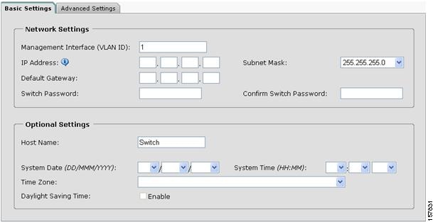
Enter this information in the Network Settings fields:
•
In the Management Interface (VLAN ID) field, the default is 1. Enter a new VLAN ID only if you want to change the management interface through which you manage the switch. The VLAN ID range is 1 to 1001.
•
In the IP Address field, enter the IP address of the switch. In the IP Subnet Mask field, click the drop-down arrow, and select an IP Subnet Mask.
•
In the Default Gateway field, enter the IP address for the default gateway (router).
•
Enter your password in the Switch Password field. The password can be from 1 to 25 alphanumeric characters, can start with a number, is case sensitive, allows embedded spaces, but does not allow spaces at the beginning or end. In the Confirm Switch Password field, enter your password again.
Step 12
(Optional) You can enter the Optional Settings information now or enter it later by using the device manager interface:
•
In the Host Name field, enter a name for the switch. The host name is limited to 31 characters. Embedded spaces are not allowed.
•
Enter the date, time, and time zone information in the System Date, System Time, and Time Zone fields. Click Enable to enable daylight saving time.
Step 13
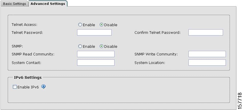
(Optional) Click the Advanced Settings tab on the Express Setup window, and enter the advanced settings now or enter them later by using the device manager interface.

Step 14
(Optional) Enter this information in the Advanced Setting fields:
•
In the Telnet Access field, click Enable if you are going to use Telnet to manage the switch by using the command-line interface (CLI). If you enable Telnet access, you must enter a Telnet password.
•
In the Telnet Password field, enter a password. The Telnet password can be from 1 to 25 alphanumeric characters, is case sensitive, allows embedded spaces, but does not allow spaces at the beginning or end. In the Confirm Telnet Password field, re-enter the Telnet password.
•
In the SNMP field, click Enable to enable Simple Network Management Protocol (SNMP). Enable SNMP only if you plan to manage switches by using CiscoWorks 2000 or another SNMP-based network-management system.
•
If you enable SNMP, you must enter a community string in the SNMP Read Community field, the SNMP Write Community field, or both. SNMP community strings authenticate access to MIB objects. Embedded spaces are not allowed in SNMP community strings. When you set the SNMP read community, you can access SNMP information, but you cannot modify it. When you set the SNMP write community, you can both access and modify SNMP information.
•
In the System Contact and System Location fields, enter a contact name and the wiring closet, floor, or building where the switch is located.
Step 15
(Optional) You can enable Internet Protocol version 6 (IPv6) on the switch. From the Advanced Settings tab, check the Enable IPv6 check box.

Note
Enabling IPv6 restarts the switch when you complete Express Setup.
Step 16
To complete Express Setup, click Submit from the Basic Settings or the Advanced Settings tab to save your settings, or click Cancel to clear your settings.
When you click Submit, the switch is configured and exits Express Setup mode. The PC displays a warning message and tries to connect with the new switch IP address. If you configured the switch with an IP address that is in a different subnet from the PC, connectivity between the PC and the switch is lost.
Step 17
Disconnect the switch from the PC, and install the switch in your production network. See the "Managing the Switch" section for information about configuring and managing the switch.
If you need to rerun Express Setup, see the "Resetting the Switch" section.
Refreshing the PC IP Address
After you complete Express Setup, you should refresh the PC IP address:
•
For a dynamically assigned IP address, disconnect the PC from the switch, and reconnect the PC to the network. The network DHCP server assigns a new IP address to the PC.
•
For a statically assigned IP address, change it to the previously configured IP address.
4 Managing the Switch
After you complete Express Setup and install the switch in your network, use the device manager or other management options described in this section for further configuration.
Using the Device Manager
The simplest way to manage the switch is by using the device manager that is in the switch memory. This is an easy-to-use web interface that offers quick configuration and monitoring. You can access the device manager from anywhere in your network through a web browser.
Follow these steps:
1.
Launch a web browser on your PC or workstation.
2.
Enter the switch IP address in the web browser, and press Enter. The device manager page appears.
3.
Use the device manager to perform basic switch configuration and monitoring. Refer to the device manager online help for more information.
4.
For more advanced configuration, download and run the Cisco Network Assistant, which is described in the next section.
Downloading Cisco Network Assistant
Cisco Network Assistant is a software program that you download from Cisco.com and run on your PC. It offers advanced options for configuring and monitoring multiple devices, including switches, switch clusters, switch stacks, routers, and access points. Network Assistant is free—there is no charge to download, install, or use it.
Follow these steps:
1.
Go to this Web address: http://www.cisco.com/go/NetworkAssistant.
You must be a registered Cisco.com user, but you need no other access privileges.
2.
Find the Network Assistant installer.
3.
Download the Network Assistant installer, and run it. (You can run it directly from the Web if your browser offers this choice.)
4.
When you run the installer, follow the displayed instructions. In the final panel, click Finish to complete the Network Assistant installation.
Refer to the Network Assistant online help and the getting started guide for more information.
Command-Line Interface
You can enter Cisco IOS commands and parameters through the CLI. Access the CLI either by connecting your PC directly to the switch console port or through a Telnet session from a remote PC or workstation.
Follow these steps:
1.
Connect the supplied RJ-45-to DB-9 adapter cable to the standard 9-pin serial port on the PC. Connect the other end of the cable to the console port on the switch.
2.
Start a terminal-emulation program on the PC.
3.
Configure the PC terminal emulation software for:
–
9600 baud
–
8 data bits
–
no parity
–
1 stop bit
–
no flow control
4.
Use the CLI to enter commands to configure the switch. See the software configuration guide and the command reference for more information.
Other Management Options
You can use SNMP management applications such as CiscoWorks Small Network Management Solution (SNMS) and HP OpenView to configure and manage the switch. You also can manage it from an SNMP-compatible workstation that is running platforms such as HP OpenView or SunNet Manager.
The Cisco IE2100 Series Configuration Registrar is a network management device that works with embedded Cisco Networking Services (CNS) agents in the switch software. You can use IE2100 to automate initial configurations and configuration updates on the switch.
See the "Accessing Help Online" section for a list of supporting documentation.
5 Planning Switch Stacks
Before connecting the Catalyst 3750 switches in a stack, keep in mind these planning considerations:
•
The size of the switch. See the"Technical Specifications" appendix of the Catalyst 3750 Switch Hardware Installation Guide for the switch dimensions. Stacking together switches of the same size makes it easier to cable the switches.
•
Length of cable. Depending on the configuration of your switch stack, you might need different sized cables. If you don't specify the length of the StackWise cable, the 0.5-meter cable is supplied. If you require the 1-meter cable or 3-meter cable, you can order it from your Cisco supplier. For cable numbers, see the Catalyst 3750 Switch Hardware Installation Guide.

Note
For concepts and procedures to manage switch stacks, refer to the switch software configuration guide.
Powering Considerations
Consider the following guidelines before you power the switches in a stack:

Note
Stack master elections occur over a 10-second timeframe on switches running releases earlier than Cisco IOS Release 12.2(20)SE3.
For more information on stack master elections, see the "Managing Switch Stacks" chapter in the switch software configuration guide.
Cabling Considerations
These illustrations show the recommended Catalyst 3750 switch stack configurations with redundant StackWise cabling connections for optimized stack bandwidth. For more configuration examples, see the Catalyst 3750 Switch Hardware Installation Guide on Cisco.com.
Vertical Stacking
In this example, the stack uses the 0.5-meter StackWise cable to make redundant connections.

In this example, the stacks use both 0.5- and 3-meter StackWise cables to make redundant connections.

Side-By-Side Stacking
In this example, eight switches are stacked side-by-side with redundant connections by using 0.5- and 3-meter StackWise cables.

In this example, nine switches are stacked side-by-side with redundant connections by using 0.5- and 3-meter StackWise cables.

6 Rack-Mounting
This section covers basic 19-inch rack-mounting and switch port connections. As an example, all the illustrations show the Catalyst 3750G-48TS switch. You can install and connect other Catalyst 3750 switches as shown in these illustrations. For alternate mounting procedures, such as installing the switch in a 24-inch rack or on a wall, and for additional cabling information, see the Catalyst 3750 Switch Hardware Installation Guide on Cisco.com.
Equipment That You Supply
You need to supply a number-2 Phillips screwdriver to rack-mount the switch.
Before You Begin
When determining where to install the switch, verify that these guidelines are met:
Installation Warning Statements
This section includes the basic installation warning statements. Translations of these warning statements appear in the Regulatory Compliance and Safety Information for the Catalyst 3750 Switch guide.

Warning
Only trained and qualified personnel should be allowed to install, replace, or service this equipment. Statement 148

Warning
To prevent the switch from overheating, do not operate it in an area that exceeds the maximum recommended ambient temperature of 113°F (45°C). To prevent airflow restriction, allow at least 3 inches (7.6 cm) of clearance around the ventilation openings. Statement 17B

Warning
Installation of the equipment must comply with local and national electrical codes. Statement 1074

Warning
This equipment is intended to be grounded. Ensure that the host is connected to earth ground during normal use. Statement 39

Warning
If a redundant power system (RPS) is not connected to the switch, install an RPS connector cover on the back of the switch. Statement 265

Warning
Class 1 laser product. Statement 1008

Warning
For connections outside the building where the equipment is installed, the following ports must be connected through an approved network termination unit with integral circuit protection: 10/100/1000 Ethernet. Statement 1044

Warning
Voltages that present a shock hazard may exist on Power over Ethernet (PoE) circuits if interconnections are made using uninsulated exposed metal contacts, conductors, or terminals. Avoid using such interconnection methods, unless the exposed metal parts are located within a restricted access location and users and service people who are authorized within the restricted access location are made aware of the hazard. A restricted access area can be accessed only through the use of a special tool, lock and key or other means of security. Statement 1072
Attaching the Brackets
Use four Phillips flat-head screws to attach the long side of the brackets to Catalyst 3750 switches in one of three mounting positions.

Rack-Mount the Switch
Use the black Phillips machine screw to attach the cable guide to the left or right bracket. Use the four number-12 Phillips machine screws to attach the brackets to the rack.

Connect the StackWise Cables
Follow these steps to connect the StackWise cable to the StackWise ports:

CautionRemoving and installing the StackWise cable can shorten its useful life. Do not remove and insert the cable more often than is absolutely necessary.

Note
Always use a Cisco-approved StackWise cable to connect the switches.
Connect to the Switch Ports
This section describes how to connect to the fixed switch ports, the SFP module ports, and the XENPAK module ports.
Connect to 10/100 and 10/100/1000 Ports
Follow these steps:
The fixed ports on the Catalyst 3750 Power over Ethernet (PoE) switches provide PoE support for devices that are compliant with IEEE 802.3af, and also provide Cisco pre-standard PoE support for Cisco IP Phones and Cisco Aironet Access Points.
Each of the Catalyst 3750-24PS switch 10/100 ports or the Catalyst 3750G-24PS switch 10/100/1000 ports can deliver up to 15.4 W of PoE. On the Catalyst 3750-48PS or 3750G-48PS switches, any 24 of the 48 10/100 or 10/100/1000 ports can deliver 15.4 W of PoE, or any combination of the ports can deliver an average of 7.7 W of PoE at the same time, up to a maximum switch power output of 370 W.
By default, a Catalyst 3750 switch PoE port automatically provides power when a valid powered device is connected to it. For information about configuring and monitoring PoE ports, see the switch software configuration guide. For information about troubleshooting PoE problems, see the Catalyst 3750 Switch Hardware Installation Guide on Cisco.com.

Note
The automatic medium-dependent interface crossover (Auto-MDIX) feature is enabled by default on switches running Cisco IOS Release 12.2(18)SE or later. When the Auto-MDIX feature is enabled, the switch detects the required cable type for copper Ethernet connections and configures the interfaces accordingly. Therefore, you can use either a crossover or a straight-through cable for connections to a copper 10/100, 10/100/1000, or 1000BASE-T SFP module port on the switch, regardless of the type of device on the other end of the connection.
Install the SFP Modules and Connect to the Ports
Follow these steps:
For a list of supported modules, see the release notes on Cisco.com. For detailed instructions on installing, removing, and connecting to SFP modules, see the documentation that came with the SFP module.

CautionRemoving and installing an SFP module can shorten its useful life. Do not remove and insert SFP modules more often than is absolutely necessary.
Verify Port Connectivity
After you connect to the switch port, the port LED turns amber while the switch establishes a link. This process takes about 30 seconds. Then the LED turns green when the switch and the target device have an established link. If the LED is off, the target device might not be turned on, there might be a cable problem, or there might be a problem with the adapter installed in the target device. See the "In Case of Difficulty" section for information about online assistance.
Install the XENPAK Module and Connect to the Ports
Follow these steps to install a XENPAK module into the XENPAK module slot on the front panel of the Catalyst 3750G-16TD switch:
See the "Verify Port Connectivity" section for instructions on how to verify that the XENPAK module ports have established a link to the external device.
7 In Case of Difficulty
If you experience difficulty, help is available in this section and also on Cisco.com. This section includes Express Setup troubleshooting, how to reset the switch, how to access help online, and where to find more information.
Troubleshooting Express Setup
If Express Setup does not run, or if the Express Setup page does not appear in your browser:
Resetting the Switch
This section describes how to reset the switch by rerunning Express Setup. These are reasons why you might want to reset the switch:
•
You installed the switch in your network and cannot connect to it because you assigned the incorrect IP address.
•
You want to clear all configuration from the switch and assign a new IP address.
•
You are trying to enter Express Setup mode, and the switch LEDs start blinking when you press the Mode button (which means that the switch is already configured with IP information).

CautionResetting the switch deletes the configuration and reboots the switch.
To reset the switch:
•
Press and hold the Mode button. The switch LEDs begin blinking after about 3 seconds. Continue holding down the Mode button. The LEDs stop blinking after 7 more seconds, and then the switch reboots.
The switch now behaves like an unconfigured switch. You can enter the switch IP information by using Express Setup as described in the "Running Express Setup" section.
Accessing Help Online
First look for a solution to your problem in the troubleshooting section of the hardware installation guide or the software configuration guide on Cisco.com. You can also access the Cisco Technical Support and Documentation website for a list of known hardware problems and extensive troubleshooting documentation.
For More Information
For more information about the switch, see these documents on Cisco.com:
•
Catalyst 3750 Switch Hardware Installation Guide
•
Regulatory Compliance and Safety Information for the Catalyst 3750 Switch
•
Release Notes for the Catalyst 3750, 3560, and 2960 Switches
•
Catalyst 3750 Switch Software Configuration Guide
•
Catalyst 3750 Switch Command Reference
•
Catalyst 3750, 3560, 2975, 2970, and 2960 Switch System Message Guide
8 Obtaining Documentation, Obtaining Support, and Security Guidelines
For information on obtaining documentation, submitting a service request, and gathering additional information, see the monthly What's New in Cisco Product Documentation, which also lists all new and revised Cisco technical documentation, at:
http://www.cisco.com/en/US/docs/general/whatsnew4/whatsnew.html
Subscribe to the What's New in Cisco Product Documentation as a Really Simple Syndication (RSS) feed and set content to be delivered directly to your desktop using a reader application. The RSS feeds are a free service and Cisco currently supports RSS Version 2.0.
9 Cisco Warranty Information
For warranty information, see the product documentation and compliance document that shipped with this product.
CCDE, CCENT, CCSI, Cisco Eos, Cisco Explorer, Cisco HealthPresence, Cisco IronPort, the Cisco logo, Cisco Nurse Connect, Cisco Pulse, Cisco SensorBase, Cisco StackPower, Cisco StadiumVision, Cisco TelePresence, Cisco TrustSec, Cisco Unified Computing System, Cisco WebEx, DCE, Flip Channels, Flip for Good, Flip Mino, Flipshare (Design), Flip Ultra, Flip Video, Flip Video (Design), Instant Broadband, and Welcome to the Human Network are trademarks; Changing the Way We Work, Live, Play, and Learn, Cisco Capital, Cisco Capital (Design), Cisco:Financed (Stylized), Cisco Store, Flip Gift Card, and One Million Acts of Green are service marks; and Access Registrar, Aironet, AllTouch, AsyncOS, Bringing the Meeting To You, Catalyst, CCDA, CCDP, CCIE, CCIP, CCNA, CCNP, CCSP, CCVP, Cisco, the Cisco Certified Internetwork Expert logo, Cisco IOS, Cisco Lumin, Cisco Nexus, Cisco Press, Cisco Systems, Cisco Systems Capital, the Cisco Systems logo, Cisco Unity, Collaboration Without Limitation, Continuum, EtherFast, EtherSwitch, Event Center, Explorer, Follow Me Browsing, GainMaker, iLYNX, IOS, iPhone, IronPort, the IronPort logo, Laser Link, LightStream, Linksys, MeetingPlace, MeetingPlace Chime Sound, MGX, Networkers, Networking Academy, PCNow, PIX, PowerKEY, PowerPanels, PowerTV, PowerTV (Design), PowerVu, Prisma, ProConnect, ROSA, SenderBase, SMARTnet, Spectrum Expert, StackWise, WebEx, and the WebEx logo are registered trademarks of Cisco and/or its affiliates in the United States and certain other countries.
All other trademarks mentioned in this document or website are the property of their respective owners. The use of the word partner does not imply a partnership relationship between Cisco and any other company. (1002R)
Any Internet Protocol (IP) addresses used in this document are not intended to be actual addresses. Any examples, command display output, and figures included in the document are shown for illustrative purposes only. Any use of actual IP addresses in illustrative content is unintentional and coincidental.
Catalyst 3750 Switch Getting Started Guide
© 2004-2010 Cisco Systems, Inc. All rights reserved.
Contact Cisco
- Open a Support Case

- (Requires a Cisco Service Contract)


 Feedback