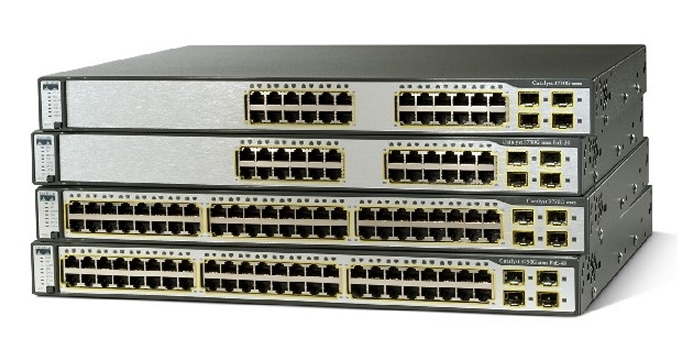
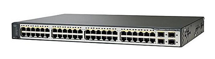
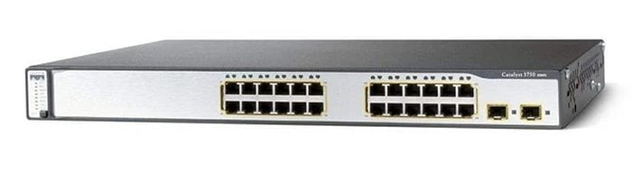
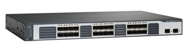
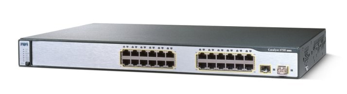
Troubleshooting


This chapter describes how to identify and resolve software problems related to the Cisco IOS software on the Catalyst 3750 switch. Depending on the nature of the problem, you can use the command-line interface (CLI), the device manager, or Network Assistant to identify and solve problems.

Unless otherwise noted, the term switch refers to a standalone switch and to a switch stack.

Additional troubleshooting information, such as LED descriptions, is provided in the hardware installation guide.


Note For complete syntax and usage information for the commands used in this chapter, see the command reference for this release and the Cisco IOS Command Summary, Release 12.2.


This chapter consists of these sections:

Recovering from a Software Failure

Recovering from a Lost or Forgotten Password

Preventing Switch Stack Problems

Recovering from a Command Switch Failure

Recovering from Lost Cluster Member Connectivity


Note Recovery procedures require that you have physical access to the switch.


Preventing Autonegotiation Mismatches

Troubleshooting Power over Ethernet Switch Ports

SFP Module Security and Identification

Monitoring SFP Module Status

Monitoring Temperature

Using Ping

Using Layer 2 Traceroute

Using IP Traceroute

Using TDR

Using Debug Commands

Using the show platform forward Command

Using the crashinfo File

Recovering from a Software Failure

Switch software can be corrupted during an upgrade, by downloading the wrong file to the switch, and by deleting the image file. In all of these cases, the switch does not pass the power-on self-test (POST), and there is no connectivity.

This procedure uses the Xmodem Protocol to recover from a corrupt or wrong image file. There are many software packages that support the Xmodem Protocol, and this procedure is largely dependent on the emulation software that you are using.

This recovery procedure requires that you have physical access to the switch.


Step 1 From your PC, download the software image tar file (image_filename.tar) from Cisco.com.

The Cisco IOS image is stored as a bin file in a directory in the tar file. For information about locating the software image files on Cisco.com, see the release notes.

Step 2 Extract the bin file from the tar file.

If you are using Windows, use a zip program that can read a tar file. Use the zip program to navigate to and extract the bin file.

If you are using UNIX, follow these steps:

1. Display the contents of the tar file by using the tar -tvf <image_filename.tar> UNIX command.

switch% tar -tvf image_filename.tar

2. Locate the bin file, and extract it by using the tar -xvf <image_filename.tar> <image_filename.bin> UNIX command.

switch% tar -xvf image_filename.tar image_filename.bin
x c3750-ipservices-mz.122-25.SEB/c3750-ipservices-mz.122-25.SEB.bin, 3970586 
bytes, 7756 tape blocks


3. Verify that the bin file was extracted by using the ls -l <image_filename.bin> UNIX command.

switch% ls -l image_filename.bin
-rw-r--r--   1 boba      3970586 Apr 21 12:00 
c3750-ipservices-mz.122-25.SEB/c3750-ipservices-mz.122-25.SEB.bin


Step 3 Connect your PC with terminal-emulation software supporting the Xmodem Protocol to the switch console port.

Step 4 Set the line speed on the emulation software to 9600 baud.

Step 5 Unplug the switch power cord.

Step 6 Press the Mode button, and at the same time, reconnect the power cord to the switch.

You can release the Mode button a second or two after the LED above port 1 goes off. Several lines of information about the software appear along with instructions:

The system has been interrupted prior to initializing the flash file system. The following 
commands will initialize the flash file system, and finish loading the operating system 
software#

flash_init
load_helper
boot

Step 7 Initialize the flash file system:

switch: flash_init

Step 8 If you had set the console port speed to anything other than 9600, it has been reset to that particular speed. Change the emulation software line speed to match that of the switch console port.

Step 9 Load any helper files:

switch: load_helper

Step 10 Start the file transfer by using the Xmodem Protocol.

switch: copy xmodem: flash:image_filename.bin

Step 11 After the Xmodem request appears, use the appropriate command on the terminal-emulation software to start the transfer and to copy the software image into flash memory.

Step 12 Boot the newly downloaded Cisco IOS image.

switch:boot flash:image_filename.bin

Step 13 Use the archive download-sw privileged EXEC command to download the software image to the switch or to the switch stack.

Step 14 Use the reload privileged EXEC command to restart the switch and to verify that the new software image is operating properly.

Step 15 Delete the flash:image_filename.bin file from the switch.


Recovering from a Lost or Forgotten Password

The default configuration for the switch allows an end user with physical access to the switch to recover from a lost password by interrupting the boot process during power-on and by entering a new password. These recovery procedures require that you have physical access to the switch.


Note On these switches, a system administrator can disable some of the functionality of this feature by allowing an end user to reset a password only by agreeing to return to the default configuration. If you are an end user trying to reset a password when password recovery has been disabled, a status message shows this during the recovery process.


These sections describes how to recover a forgotten or lost switch password:

Procedure with Password Recovery Enabled

Procedure with Password Recovery Disabled

You enable or disable password recovery by using the service password-recovery global configuration command. When you enter the service password-recovery or no service password-recovery command on the stack master, it is propagated throughout the stack and applied to all switches in the stack.

Follow the steps in this procedure if you have forgotten or lost the switch password.


Step 1 Connect a terminal or PC with terminal-emulation software to the switch console port. If you are recovering the password to a switch stack, connect to the console port of the stack master.

Step 2 Set the line speed on the emulation software to 9600 baud.

Step 3 Power off the standalone switch or the entire switch stack.

Step 4 Reconnect the power cord to the standalone switch or the stack master and, within 15 seconds, press the Mode button while the System LED is still flashing green. Continue pressing the Mode button until the System LED turns briefly amber and then solid green; then release the Mode button.

Several lines of information about the software appear with instructions, informing you if the password recovery procedure has been disabled or not.

If you see a message that begins with this:

The system has been interrupted prior to initializing the flash file system. The 
following commands will initialize the flash file system

proceed to the "Procedure with Password Recovery Enabled" section, and follow the steps.

If you see a message that begins with this:

The password-recovery mechanism has been triggered, but is currently disabled. 

proceed to the "Procedure with Password Recovery Disabled" section, and follow the steps.

Step 5 After recovering the password, reload the standalone switch or the stack master:

Switch> reload slot <stack-master-member-number>
Proceed with reload? [confirm] y

Step 6 Power on the rest of the switch stack.


Procedure with Password Recovery Enabled

If the password-recovery mechanism is enabled, this message appears:

The system has been interrupted prior to initializing the flash file system. The following 
commands will initialize the flash file system, and finish loading the operating system 
software:

flash_init
load_helper
boot

Step 1 Initialize the flash file system:

switch: flash_init

Step 2 If you had set the console port speed to anything other than 9600, it has been reset to that particular speed. Change the emulation software line speed to match that of the switch console port.

Step 3 Load any helper files:

switch: load_helper

Step 4 Display the contents of flash memory:

switch: dir flash:

The switch file system appears:

Directory of flash:
   13  drwx         192   Mar 01 1993 22:30:48  c3750-ipservices-mz-122-25.SEB
   11  -rwx        5825   Mar 01 1993 22:31:59  config.text
   18  -rwx         720   Mar 01 1993 02:21:30  vlan.dat

16128000 bytes total (10003456 bytes free) 

Step 5 Rename the configuration file to config.text.old.

This file contains the password definition.

switch: rename flash:config.text flash:config.text.old

Step 6 Boot the system:

switch: boot

You are prompted to start the setup program. Enter N at the prompt:

Continue with the configuration dialog? [yes/no]: N

Step 7 At the switch prompt, enter privileged EXEC mode:

Switch> enable

Step 8 Rename the configuration file to its original name:

Switch# rename flash:config.text.old flash:config.text 


Note Before continuing to Step 9, power on any connected stack members and wait until they have completely initialized. Failure to follow this step can result in a lost configuration depending on how your switch is set up.


Step 9 Copy the configuration file into memory:

Switch# copy flash:config.text system:running-config 
Source filename [config.text]? 
Destination filename [running-config]?

Press Return in response to the confirmation prompts.

The configuration file is now reloaded, and you can change the password.

Step 10 Enter global configuration mode:

Switch# configure terminal

Step 11 Change the password:

Switch (config)# enable secret password

The secret password can be from 1 to 25 alphanumeric characters, can start with a number, is case sensitive, and allows spaces but ignores leading spaces.

Step 12 Return to privileged EXEC mode:

Switch (config)# exit 
Switch# 

Step 13 Write the running configuration to the startup configuration file:

Switch# copy running-config startup-config

The new password is now in the startup configuration.


Note This procedure is likely to leave your switch virtual interface in a shutdown state. You can see which interface is in this state by entering the show running-config privileged EXEC command. To re-enable the interface, enter the interface vlan vlan-id global configuration command, and specify the VLAN ID of the shutdown interface. With the switch in interface configuration mode, enter the no shutdown command.


Step 14 Reload the switch stack:

Switch# reload


Procedure with Password Recovery Disabled

If the password-recovery mechanism is disabled, this message appears:

The password-recovery mechanism has been triggered, but
is currently disabled.  Access to the boot loader prompt
through the password-recovery mechanism is disallowed at
this point.  However, if you agree to let the system be
reset back to the default system configuration, access
to the boot loader prompt can still be allowed.

Would you like to reset the system back to the default configuration (y/n)?

Caution Returning the switch to the default configuration results in the loss of all existing configurations. We recommend that you contact your system administrator to verify if there are backup switch and VLAN configuration files.

If you enter n (no), the normal boot process continues as if the Mode button had not been pressed; you cannot access the boot loader prompt, and you cannot enter a new password. You see the message:

Press Enter to continue........

If you enter y (yes), the configuration file in flash memory and the VLAN database file are deleted. When the default configuration loads, you can reset the password.


Step 1 Elect to continue with password recovery and lose the existing configuration:

Would you like to reset the system back to the default configuration (y/n)? Y 

Step 2 Load any helper files:

Switch: load_helper

Step 3 Display the contents of flash memory:

switch: dir flash:

The switch file system appears:

Directory of flash:
13  drwx         192   Mar 01 1993 22:30:48 c3750-ipservice-mz-122-25.0

16128000 bytes total (10003456 bytes free) 

Step 4 Boot the system:

Switch: boot

You are prompted to start the setup program. To continue with password recovery, enter N at the prompt:

Continue with the configuration dialog? [yes/no]: N

Step 5 At the switch prompt, enter privileged EXEC mode:

Switch> enable

Step 6 Enter global configuration mode:

Switch# configure terminal

Step 7 Change the password:

Switch (config)# enable secret password

The secret password can be from 1 to 25 alphanumeric characters, can start with a number, is case sensitive, and allows spaces but ignores leading spaces.

Step 8 Return to privileged EXEC mode:

Switch (config)# exit 
Switch# 


Note Before continuing to Step 9, power on any connected stack members and wait until they have completely initialized.


Step 9 Write the running configuration to the startup configuration file:

Switch# copy running-config startup-config

The new password is now in the startup configuration.


Note This procedure is likely to leave your switch virtual interface in a shutdown state. You can see which interface is in this state by entering the show running-config privileged EXEC command. To re-enable the interface, enter the interface vlan vlan-id global configuration command, and specify the VLAN ID of the shutdown interface. With the switch in interface configuration mode, enter the no shutdown command.


Step 10 You must now reconfigure the switch. If the system administrator has the backup switch and VLAN configuration files available, you should use those.


Preventing Switch Stack Problems


NoteMake sure that the switches that you add to or remove from the switch stack are powered off. For all powering considerations in switch stacks, see the "Switch Installation" chapter in the hardware installation guide.

After adding or removing stack members, make sure that the switch stack is operating at full bandwidth (32 Gbps). Press the Mode button on a stack member until the Stack mode LED is on. The last two port LEDs on the switch should be green. Depending on the switch model, the last two ports are either 10/100/1000 ports or small form-factor pluggable (SFP) module ports. If one or both of the last two port LEDs are not green, the stack is not operating at full bandwidth.

We recommend using only one CLI session when managing the switch stack. Be careful when using multiple CLI sessions to the stack master. Commands that you enter in one session are not displayed in the other sessions. Therefore, it is possible that you might not be able to identify the session from which you entered a command.

Manually assigning stack member numbers according to the placement of the switches in the stack can make it easier to remotely troubleshoot the switch stack. However, you need to remember that the switches have manually assigned numbers if you add, remove, or rearrange switches later. Use the switch current-stack-member-number renumber new-stack-member-number global configuration command to manually assign a stack member number. For more information about stack member numbers, see the "Stack Member Numbers" section.


If you replace a stack member with an identical model, the new switch functions with the exact same configuration as the replaced switch. This is also assuming the new switch is using the same member number as the replaced switch.

Removing powered-on stack members causes the switch stack to divide (partition) into two or more switch stacks, each with the same configuration. If you want the switch stacks to remain separate, change the IP address or addresses of the newly created switch stacks. To recover from a partitioned switch stack:

1. Power off the newly created switch stacks.

2. Reconnect them to the original switch stack through their StackWise ports.

3. Power on the switches.

For the commands that you can use to monitor the switch stack and its members, see the "Displaying Switch Stack Information" section.

Recovering from a Command Switch Failure

This section describes how to recover from a failed command switch. You can configure a redundant command switch group by using the Hot Standby Router Protocol (HSRP). For more information, see "Clustering Switches" and "Configuring HSRP." Also see the Getting Started with Cisco Network Assistant, available on Cisco.com.


Note HSRP is the preferred method for supplying redundancy to a cluster.


If you have not configured a standby command switch, and your command switch loses power or fails in some other way, management contact with the member switches is lost, and you must install a new command switch. However, connectivity between switches that are still connected is not affected, and the member switches forward packets as usual. You can manage the members as standalone switches through the console port or, if they have IP addresses, through the other management interfaces.

You can prepare for a command switch failure by assigning an IP address to a member switch or another switch that is command-capable, making a note of the command-switch password, and cabling your cluster to provide redundant connectivity between the member switches and the replacement command switch. These sections describe two solutions for replacing a failed command switch:

Replacing a Failed Command Switch with a Cluster Member

Replacing a Failed Command Switch with Another Switch

These recovery procedures require that you have physical access to the switch.

For information on command-capable switches, see the release notes.

Replacing a Failed Command Switch with a Cluster Member

To replace a failed command switch with a command-capable member in the same cluster, follow these steps:


Step 1 Disconnect the command switch from the member switches, and physically remove it from the cluster.

Step 2 Insert the member switch in place of the failed command switch, and duplicate its connections to the cluster members.

Step 3 Start a CLI session on the new command switch.

You can access the CLI by using the console port or, if an IP address has been assigned to the switch, by using Telnet. For details about using the console port, see the switch hardware installation guide.

Step 4 At the switch prompt, enter privileged EXEC mode:

Switch> enable 
Switch#

Step 5 Enter the password of the failed command switch.

Step 6 Enter global configuration mode.

Switch# configure terminal 
Enter configuration commands, one per line.  End with CNTL/Z.

Step 7 Remove the member switch from the cluster.

Switch(config)# no cluster commander-address 

Step 8 Return to privileged EXEC mode.

Switch(config)# end 
Switch#

Step 9 Use the setup program to configure the switch IP information. This program prompts you for IP address information and passwords. From privileged EXEC mode, enter setup, and press Return.

Switch# setup
         --- System Configuration Dialog ---
Continue with configuration dialog? [yes/no]: y

At any point you may enter a question mark '?' for help.
Use ctrl-c to abort configuration dialog at any prompt.
Default settings are in square brackets '[]'.

Basic management setup configures only enough connectivity
for management of the system, extended setup will ask you
to configure each interface on the system

Would you like to enter basic management setup? [yes/no]: 

Step 10 Enter Y at the first prompt.

The prompts in the setup program vary depending on the member switch you selected to be the command switch:

Continue with configuration dialog? [yes/no]: y

or

Configuring global parameters:

If this prompt does not appear, enter enable, and press Return. Enter setup, and press Return to start the setup program.

Step 11 Respond to the questions in the setup program.

When prompted for the hostname, recall that on a command switch, the hostname is limited to 28 characters; on a member switch to 31 characters. Do not use -n, where n is a number, as the last characters in a hostname for any switch.

When prompted for the Telnet (virtual terminal) password, recall that it can be from 1 to 25 alphanumeric characters, is case sensitive, allows spaces, but ignores leading spaces.

Step 12 When prompted for the enable secret and enable passwords, enter the passwords of the failed command switch again.

Step 13 When prompted, make sure to enable the switch as the cluster command switch, and press Return.

Step 14 When prompted, assign a name to the cluster, and press Return.

The cluster name can be 1 to 31 alphanumeric characters, dashes, or underscores.

Step 15 After the initial configuration displays, verify that the addresses are correct.

Step 16 If the displayed information is correct, enter Y, and press Return.

If this information is not correct, enter N, press Return, and begin again at Step 9.

Step 17 Start your browser, and enter the IP address of the new command switch.

Step 18 From the Cluster menu, select Add to Cluster to display a list of candidate switches to add to the cluster.


Replacing a Failed Command Switch with Another Switch

To replace a failed command switch with a switch that is command-capable but not part of the cluster, follow these steps:


Step 1 Insert the new switch in place of the failed command switch, and duplicate its connections to the cluster members.

Step 2 Start a CLI session on the new command switch.

You can access the CLI by using the console port or, if an IP address has been assigned to the switch, by using Telnet. For details about using the console port, see the switch hardware installation guide.

Step 3 At the switch prompt, enter privileged EXEC mode:

Switch> enable 
Switch#

Step 4 Enter the password of the failed command switch.

Step 5 Use the setup program to configure the switch IP information.

This program prompts you for IP address information and passwords. From privileged EXEC mode, enter setup, and press Return.

Switch# setup
         --- System Configuration Dialog ---
Continue with configuration dialog? [yes/no]: y

At any point you may enter a question mark '?' for help.
Use ctrl-c to abort configuration dialog at any prompt.
Default settings are in square brackets '[]'.

Basic management setup configures only enough connectivity
for management of the system, extended setup will ask you
to configure each interface on the system

Would you like to enter basic management setup? [yes/no]: 

Step 6 Enter Y at the first prompt.

The prompts in the setup program vary depending on the switch you selected to be the command switch:

Continue with configuration dialog? [yes/no]: y

or

Configuring global parameters:

If this prompt does not appear, enter enable, and press Return. Enter setup, and press Return to start the setup program.

Step 7 Respond to the questions in the setup program.

When prompted for the hostname, recall that on a command switch, the hostname is limited to 28 characters. Do not use -n, where n is a number, as the last characters in a hostname for any switch.

When prompted for the Telnet (virtual terminal) password, recall that it can be from 1 to 25 alphanumeric characters, is case sensitive, allows spaces, but ignores leading spaces.

Step 8 When prompted for the enable secret and enable passwords, enter the passwords of the failed command switch again.

Step 9 When prompted, make sure to enable the switch as the cluster command switch, and press Return.

Step 10 When prompted, assign a name to the cluster, and press Return.

The cluster name can be 1 to 31 alphanumeric characters, dashes, or underscores.

Step 11 When the initial configuration displays, verify that the addresses are correct.

Step 12 If the displayed information is correct, enter Y, and press Return.

If this information is not correct, enter N, press Return, and begin again at Step 9.

Step 13 Start your browser, and enter the IP address of the new command switch.

Step 14 From the Cluster menu, select Add to Cluster to display a list of candidate switches to add to the cluster.


Recovering from Lost Cluster Member Connectivity

Some configurations can prevent the command switch from maintaining contact with member switches. If you are unable to maintain management contact with a member, and the member switch is forwarding packets normally, check for these conflicts:

A member switch (Catalyst 3750, Catalyst 3560, Catalyst 3550, Catalyst 3500 XL, Catalyst 2970, Catalyst 2960, Catalyst 2950, Catalyst 2900 XL, Catalyst 2820, and Catalyst 1900 switch) cannot connect to the command switch through a port that is defined as a network port.

Catalyst 3500 XL, Catalyst 2900 XL, Catalyst 2820, and Catalyst 1900 member switches must connect to the command switch through a port that belongs to the same management VLAN.

A member switch (Catalyst 3750, Catalyst 3560, Catalyst 3550, Catalyst 2970, Catalyst 2960, Catalyst 2950, Catalyst 3500 XL, Catalyst 2900 XL, Catalyst 2820, and Catalyst 1900 switch) connected to the command switch through a secured port can lose connectivity if the port is disabled because of a security violation.

Preventing Autonegotiation Mismatches

The IEEE 802.3ab autonegotiation protocol manages the switch settings for speed (10 Mbps, 100 Mbps, and 1000 Mbps, excluding SFP module ports) and duplex (half or full). There are situations when this protocol can incorrectly align these settings, reducing performance. A mismatch occurs under these circumstances:

A manually set speed or duplex parameter is different from the manually set speed or duplex parameter on the connected port.

A port is set to autonegotiate, and the connected port is set to full duplex with no autonegotiation.

To maximize switch performance and ensure a link, follow one of these guidelines when changing the settings for duplex and speed:

Let both ports autonegotiate both speed and duplex.

Manually set the speed and duplex parameters for the ports on both ends of the connection.


Note If a remote device does not autonegotiate, configure the duplex settings on the two ports to match. The speed parameter can adjust itself even if the connected port does not autonegotiate.


Troubleshooting Power over Ethernet Switch Ports

These sections describe how to troubleshoot Power over Ethernet (PoE) ports.

Disabled Port Caused by Power Loss

If a powered device (such as a Cisco IP Phone 7910) that is connected to a PoE switch port and is powered by an AC power source loses power from the AC power source, the device might enter an error-disabled state. To recover from an error-disabled state, enter the shutdown interface configuration command, and then enter the no shutdown interface command. You can also configure automatic recovery on the switch to recover from the error-disabled state. The errdisable recovery cause loopback and the errdisable recovery interval seconds global configuration commands automatically take the interface out of the error-disabled state after the specified period of time.

Use these commands, described in the command reference for this release, to monitor the PoE port status:

show controllers power inline privileged EXEC command

show power inline privileged EXEC command

debug ilpower privileged EXEC command

Disabled Port Caused by False Link Up

If a Cisco powered device is connected to a port and you configure the port by using the power inline never interface configuration command, a false link up can occur, placing the port into an error-disabled state. To take the port out of the error-disabled state, enter the shutdown and the no shutdown interface configuration commands.

You should not connect a Cisco powered device to a port that has been configured with the power inline never command.

SFP Module Security and Identification

Cisco small form-factor pluggable (SFP) modules have a serial EEPROM that contains the module serial number, the vendor name and ID, a unique security code, and cyclic redundancy check (CRC). When an SFP module is inserted in the switch, the switch software reads the EEPROM to verify the serial number, vendor name and vendor ID, and recompute the security code and CRC. If the serial number, the vendor name or vendor ID, the security code, or CRC is invalid, the software generates a security error message and places the interface in an error-disabled state.


Note The security error message references the GBIC_SECURITY facility. The switch supports SFP modules and does not support GBIC modules. Although the error message text refers to GBIC interfaces and modules, the security messages actually refer to the SFP modules and module interfaces. For more information about error messages, see the system message guide for this release.


If you are using a non-Cisco SFP module, remove the SFP module from the switch, and replace it with a Cisco module. After inserting a Cisco SFP module, use the errdisable recovery cause gbic-invalid global configuration command to verify the port status, and enter a time interval for recovering from the error-disabled state. After the elapsed interval, the switch brings the interface out of the error-disabled state and retries the operation. For more information about the errdisable recovery command, see the command reference for this release.

If the module is identified as a Cisco SFP module, but the system is unable to read vendor-data information to verify its accuracy, an SFP module error message is generated. In this case, you should remove and re-insert the SFP module. If it continues to fail, the SFP module might be defective.

Monitoring SFP Module Status

You can check the physical or operational status of an SFP module by using the show interfaces transceiver privileged EXEC command. This command shows the operational status, such as the temperature and the current for an SFP module on a specific interface and the alarm status. You can also use the command to check the speed and the duplex settings on an SFP module. For more information, see the show interfaces transceiver command in the command reference for this release.

Monitoring Temperature

The Catalyst 3750G-48TS, 3750G-48PS, 3750G-24TS-1U, and 3750G-24PS switches monitor the temperature conditions. The switch also uses the temperature information to control the fans.

Use the show env temperature status privileged EXEC command to display the temperature value, state, and thresholds. The temperature value is the temperature in the switch (not the external temperature).You can configure only the yellow threshold level (in Celsius) by using the system env temperature threshold yellow value global configuration command to set the difference between the yellow and red thresholds. You cannot configure the green or red thresholds. For more information, see the command reference for this release.

Using Ping

These sections contain this information:

Understanding Ping

Executing Ping

Understanding Ping

The switch supports IP ping, which you can use to test connectivity to remote hosts. Ping sends an echo request packet to an address and waits for a reply. Ping returns one of these responses:

Normal response—The normal response (hostname is alive) occurs in 1 to 10 seconds, depending on network traffic.

Destination does not respond—If the host does not respond, a no-answer message is returned.

Unknown host—If the host does not exist, an unknown host message is returned.

Destination unreachable—If the default gateway cannot reach the specified network, a destination-unreachable message is returned.

Network or host unreachable—If there is no entry in the route table for the host or network, a network or host unreachable message is returned.

Executing Ping

If you attempt to ping a host in a different IP subnetwork, you must define a static route to the network or have IP routing configured to route between those subnets. For more information, see "Configuring IP Unicast Routing."

IP routing is disabled by default on all switches. If you need to enable or configure IP routing, see "Configuring IP Unicast Routing."

Beginning in privileged EXEC mode, use this command to ping another device on the network from the switch:

Command
Purpose

ping ip host | address

Ping a remote host through IP or by supplying the hostname or network address.


Note Though other protocol keywords are available with the ping command, they are not supported in this release.


This example shows how to ping an IP host:

Switch# ping 172.20.52.3

Type escape sequence to abort.
Sending 5, 100-byte ICMP Echoes to 172.20.52.3, timeout is 2 seconds:
!!!!!
Success rate is 100 percent (5/5), round-trip min/avg/max = 1/2/4 ms
Switch#

Table 41-1 describes the possible ping character output.

Table 41-1 Ping Output Display Characters 

Character
Description

!

Each exclamation point means receipt of a reply.

.

Each period means the network server timed out while waiting for a reply.

U

A destination unreachable error PDU was received.

C

A congestion experienced packet was received.

I

User interrupted test.

?

Unknown packet type.

&

Packet lifetime exceeded.


To end a ping session, enter the escape sequence (Ctrl-^ X by default). Simultaneously press and release the Ctrl, Shift, and 6 keys and then press the X key.

Using Layer 2 Traceroute

These sections contain this information:

Understanding Layer 2 Traceroute

Usage Guidelines

Displaying the Physical Path

Understanding Layer 2 Traceroute

The Layer 2 traceroute feature allows the switch to identify the physical path that a packet takes from a source device to a destination device. Layer 2 traceroute supports only unicast source and destination MAC addresses. It finds the path by using the MAC address tables of the switches in the path. When the switch detects a device in the path that does not support Layer 2 traceroute, the switch continues to send Layer 2 trace queries and lets them time out.

The switch can only identify the path from the source device to the destination device. It cannot identify the path that a packet takes from source host to the source device or from the destination device to the destination host.

Usage Guidelines

These are the Layer 2 traceroute usage guidelines:

Cisco Discovery Protocol (CDP) must be enabled on all the devices in the network. For Layer 2 traceroute to function properly, do not disable CDP.

For a list of switches that support Layer 2 traceroute, see the "Usage Guidelines" section. If any devices in the physical path are transparent to CDP, the switch cannot identify the path through these devices. For more information about enabling CDP, see "Configuring CDP."

A switch is reachable from another switch when you can test connectivity by using the ping privileged EXEC command. All switches in the physical path must be reachable from each other.

The maximum number of hops identified in the path is ten.

You can enter the traceroute mac or the traceroute mac ip privileged EXEC command on a switch that is not in the physical path from the source device to the destination device. All switches in the path must be reachable from this switch.

The traceroute mac command output shows the Layer 2 path only when the specified source and destination MAC addresses belong to the same VLAN. If you specify source and destination MAC addresses that belong to different VLANs, the Layer 2 path is not identified, and an error message appears.

If you specify a multicast source or destination MAC address, the path is not identified, and an error message appears.

If the source or destination MAC address belongs to multiple VLANs, you must specify the VLAN to which both the source and destination MAC addresses belong. If the VLAN is not specified, the path is not identified, and an error message appears.

The traceroute mac ip command output shows the Layer 2 path when the specified source and destination IP addresses belong to the same subnet. When you specify the IP addresses, the switch uses the Address Resolution Protocol (ARP) to associate the IP addresses with the corresponding MAC addresses and the VLAN IDs.

If an ARP entry exists for the specified IP address, the switch uses the associated MAC address and identifies the physical path.

If an ARP entry does not exist, the switch sends an ARP query and tries to resolve the IP address. If the IP address is not resolved, the path is not identified, and an error message appears.

When multiple devices are attached to one port through hubs (for example, multiple CDP neighbors are detected on a port), the Layer 2 traceroute feature is not supported. When more than one CDP neighbor is detected on a port, the Layer 2 path is not identified, and an error message appears.

This feature is not supported in Token Ring VLANs.

Displaying the Physical Path

You can display physical path that a packet takes from a source device to a destination device by using one of these privileged EXEC commands:

tracetroute mac [interface interface-id] {source-mac-address} [interface interface-id] {destination-mac-address} [vlan vlan-id] [detail]

tracetroute mac ip {source-ip-address | source-hostname}{destination-ip-address | destination-hostname} [detail]

For more information, see the command reference for this release.

Using IP Traceroute

These sections contain this information:

Understanding IP Traceroute

Executing IP Traceroute

Understanding IP Traceroute

You can use IP traceroute to identify the path that packets take through the network on a hop-by-hop basis. The command output displays all network layer (Layer 3) devices, such as routers, that the traffic passes through on the way to the destination.

Your switches can participate as the source or destination of the traceroute privileged EXEC command and might or might not appear as a hop in the traceroute command output. If the switch is the destination of the traceroute, it is displayed as the final destination in the traceroute output. Intermediate switches do not show up in the traceroute output if they are only bridging the packet from one port to another within the same VLAN. However, if the intermediate switch is a multilayer switch that is routing a particular packet, this switch shows up as a hop in the traceroute output.

The traceroute privileged EXEC command uses the Time To Live (TTL) field in the IP header to cause routers and servers to generate specific return messages. Traceroute starts by sending a User Datagram Protocol (UDP) datagram to the destination host with the TTL field set to 1. If a router finds a TTL value of 1 or 0, it drops the datagram and sends an Internet Control Message Protocol (ICMP) time-to-live-exceeded message to the sender. Traceroute finds the address of the first hop by examining the source address field of the ICMP time-to-live-exceeded message.

To identify the next hop, traceroute sends a UDP packet with a TTL value of 2. The first router decrements the TTL field by 1 and sends the datagram to the next router. The second router sees a TTL value of 1, discards the datagram, and returns the time-to-live-exceeded message to the source. This process continues until the TTL is incremented to a value large enough for the datagram to reach the destination host (or until the maximum TTL is reached).

To learn when a datagram reaches its destination, traceroute sets the UDP destination port number in the datagram to a very large value that the destination host is unlikely to be using. When a host receives a datagram destined to itself containing a destination port number that is unused locally, it sends an ICMP port-unreachable error to the source. Because all errors except port-unreachable errors come from intermediate hops, the receipt of a port-unreachable error means that this message was sent by the destination port.

Executing IP Traceroute

Beginning in privileged EXEC mode, follow this step to trace that the path packets take through the network:

Command
Purpose

traceroute ip host

Trace the path that packets take through the network.


Note Though other protocol keywords are available with the traceroute privileged EXEC command, they are not supported in this release.


This example shows how to perform a traceroute to an IP host:

Switch# traceroute ip 171.9.15.10

Type escape sequence to abort.
Tracing the route to 171.69.115.10

  1 172.2.52.1 0 msec 0 msec 4 msec
  2 172.2.1.203 12 msec 8 msec 0 msec
  3 171.9.16.6 4 msec 0 msec 0 msec
  4 171.9.4.5 0 msec 4 msec 0 msec
  5 171.9.121.34 0 msec 4 msec 4 msec
  6 171.9.15.9 120 msec 132 msec 128 msec
  7 171.9.15.10 132 msec 128 msec 128 msec
Switch#

The display shows the hop count, IP address of the router, and the round-trip time in milliseconds for each of the three probes that are sent.

Table 41-2 Traceroute Output Display Characters 

Character
Description

*

The probe timed out.

?

Unknown packet type.

A

Administratively unreachable. Usually, this output means that an access list is blocking traffic.

H

Host unreachable.

N

Network unreachable.

P

Protocol unreachable.

Q

Source quench.

U

Port unreachable.


To end a trace in progress, enter the escape sequence (Ctrl-^ X by default). Simultaneously press and release the Ctrl, Shift, and 6 keys and then press the X key.

Using TDR

These sections contain this information:

Understanding TDR

Running TDR and Displaying the Results

Understanding TDR

In Cisco IOS Release 12.1(19)EA1 or later, you can use the Time Domain Reflector (TDR) feature to diagnose and resolve cabling problems. When running TDR, a local device sends a signal through a cable and compares the reflected signal to the initial signal.

TDR is supported only on copper Ethernet 10/100/1000 ports. It is not supported on 10/100 ports or SFP module ports.

TDR can detect these cabling problems:

Open, broken, or cut twisted-pair wires—The wires are not connected to the wires from the remote device.

Shorted twisted-pair wires—The wires are touching each other or the wires from the remote device. For example, a shorted twisted pair can occur if one wire of the twisted pair is soldered to the other wire.

If one of the twisted-pair wires is open, TDR can find the length at which the wire is open.

Use TDR to diagnose and resolve cabling problems in these situations:

Replacing a switch

Setting up a wiring closet

Troubleshooting a connection between two devices when a link cannot be established or when it is not operating properly

Running TDR and Displaying the Results

When you run TDR on an interface, you can run it on the stack master or a stack member.

To run TDR, enter the test cable-diagnostics tdr interface interface-id privileged EXEC command:

To display the results, enter the show cable-diagnostics tdr interface interface-id privileged EXEC command. For a description of the fields in the display, see the command reference for this release.

Using Debug Commands

These sections explains how you use debug commands to diagnose and resolve internetworking problems:

Enabling Debugging on a Specific Feature

Enabling All-System Diagnostics

Redirecting Debug and Error Message Output


Caution Because debugging output is assigned high priority in the CPU process, it can render the system unusable. For this reason, use debug commands only to troubleshoot specific problems or during troubleshooting sessions with Cisco technical support staff. It is best to use debug commands during periods of lower network traffic and fewer users. Debugging during these periods decreases the likelihood that increased debug command processing overhead will affect system use.


Note For complete syntax and usage information for specific debug commands, see the command reference for this release.


Enabling Debugging on a Specific Feature

When you enable debugging, it is enabled only on the stack master. To enable debugging on a stack member, you must start a session from the stack master by using the session switch-number privileged EXEC command. Then, enter the debug command at the command-line prompt of the stack member.

All debug commands are entered in privileged EXEC mode, and most debug commands take no arguments. For example, beginning in privileged EXEC mode, enter this command to enable the debugging for Switched Port Analyzer (SPAN):

Switch# debug span-session

The switch continues to generate output until you enter the no form of the command.

If you enable a debug command and no output appears, consider these possibilities:

The switch might not be properly configured to generate the type of traffic you want to monitor. Use the show running-config command to check its configuration.

Even if the switch is properly configured, it might not generate the type of traffic you want to monitor during the particular period that debugging is enabled. Depending on the feature you are debugging, you can use commands such as the TCP/IP ping command to generate network traffic.

To disable debugging of SPAN, enter this command in privileged EXEC mode:

Switch# no debug span-session

Alternately, in privileged EXEC mode, you can enter the undebug form of the command:

Switch# undebug span-session

To display the state of each debugging option, enter this command in privileged EXEC mode:

Switch# show debugging

Enabling All-System Diagnostics

Beginning in privileged EXEC mode, enter this command to enable all-system diagnostics:

Switch# debug all


Caution Because debugging output takes priority over other network traffic, and because the debug all privileged EXEC command generates more output than any other debug command, it can severely diminish switch performance or even render it unusable. In virtually all cases, it is best to use more specific debug commands.

The no debug all privileged EXEC command disables all diagnostic output. Using the no debug all command is a convenient way to ensure that you have not accidentally left any debug commands enabled.

Redirecting Debug and Error Message Output

By default, the network server sends the output from debug commands and system error messages to the console. If you use this default, you can use a virtual terminal connection to monitor debug output instead of connecting to the console port.

Possible destinations include the console, virtual terminals, internal buffer, and UNIX hosts running a syslog server. The syslog format is compatible with 4.3 Berkeley Standard Distribution (BSD) UNIX and its derivatives.


Note Be aware that the debugging destination you use affects system overhead. Logging messages to the console produces very high overhead, whereas logging messages to a virtual terminal produces less overhead. Logging messages to a syslog server produces even less, and logging to an internal buffer produces the least overhead of any method.


When stack members generate a system error message, the stack master displays the error message to all stack members. The syslog resides on the stack master.


Note Make sure to save the syslog to flash memory so that the syslog is not lost if the stack master fails.


For more information about system message logging, see "Configuring System Message Logging."

Using the show platform forward Command

The output from the show platform forward privileged EXEC command provides some useful information about the forwarding results if a packet entering an interface is sent through the system. Depending upon the parameters entered about the packet, the output provides lookup table results and port maps used to calculate forwarding destinations, bitmaps, and egress information.


Note For more syntax and usage information for the show platform forward command, see the switch command reference for this release.


Most of the information in the output from the command is useful mainly for technical support personnel, who have access to detailed information about the switch application-specific integrated circuits (ASICs). However, packet forwarding information can also be helpful in troubleshooting.

This is an example of the output from the show platform forward command on port 1 in VLAN 5 when the packet entering that port is addressed to unknown MAC addresses. The packet should be flooded to all other ports in VLAN 5.

Switch# show platform forward gigabitethernet1/0/1 vlan 5 1.1.1 2.2.2 ip 13.1.1.1 13.2.2.2 
udp 10 20     
Global Port Number:24, Asic Number:5
Src Real Vlan Id:5, Mapped Vlan Id:5

Ingress:
 Lookup                   Key-Used                    Index-Hit  A-Data
InptACL  40_0D020202_0D010101-00_40000014_000A0000     01FFA   03000000
L2Local  80_00050002_00020002-00_00000000_00000000     00C71   0000002B
Station Descriptor:02340000, DestIndex:0239, RewriteIndex:F005

==========================================
Egress:Asic 2, switch 1
Output Packets:

------------------------------------------
Packet 1
 Lookup                   Key-Used                    Index-Hit  A-Data
OutptACL 50_0D020202_0D010101-00_40000014_000A0000     01FFE   03000000

Port       Vlan      SrcMac          DstMac    Cos  Dscpv
Gi1/0/1    0005 0001.0001.0001  0002.0002.0002  

------------------------------------------
Packet 2
 Lookup                   Key-Used                    Index-Hit  A-Data
OutptACL 50_0D020202_0D010101-00_40000014_000A0000     01FFE   03000000

Port       Vlan      SrcMac          DstMac    Cos  Dscpv
Gi1/0/2    0005 0001.0001.0001  0002.0002.0002  

------------------------------------------
<output truncated>
------------------------------------------
Packet 10
 Lookup                   Key-Used                    Index-Hit  A-Data
OutptACL 50_0D020202_0D010101-00_40000014_000A0000     01FFE   03000000
Packet dropped due to failed DEJA_VU Check on Gi1/0/2

This is an example of the output when the packet coming in on port 1 in VLAN 5 is sent to an address already learned on the VLAN on another port. It should be forwarded from the port on which the address was learned.

Switch# show platform forward gigabitethernet1/0/1 vlan 5 1.1.1 0009.43a8.0145 ip 13.1.1.1 
13.2.2.2 udp 10 20
Global Port Number:24, Asic Number:5
Src Real Vlan Id:5, Mapped Vlan Id:5

Ingress:
 Lookup                   Key-Used                    Index-Hit  A-Data
InptACL  40_0D020202_0D010101-00_40000014_000A0000     01FFA   03000000
L2Local  80_00050009_43A80145-00_00000000_00000000     00086   02010197
Station Descriptor:F0050003, DestIndex:F005, RewriteIndex:0003

==========================================
Egress:Asic 3, switch 1
Output Packets:

------------------------------------------
Packet 1
 Lookup                   Key-Used                    Index-Hit  A-Data
OutptACL 50_0D020202_0D010101-00_40000014_000A0000     01FFE   03000000

Port       Vlan      SrcMac          DstMac    Cos  Dscpv
Gi1/0/2    0005 0001.0001.0001  0009.43A8.0145 

This is an example of the output when the packet coming in on port 1 in VLAN 5 has a destination MAC address set to the router MAC address in VLAN 5 and the destination IP address unknown. Because there is no default route set, the packet should be dropped.

Switch# show platform forward gigabitethernet1/0/1 vlan 5 1.1.1 03.e319.ee44 ip 13.1.1.1 
13.2.2.2 udp 10 20
Global Port Number:24, Asic Number:5
Src Real Vlan Id:5, Mapped Vlan Id:5

Ingress:
 Lookup                   Key-Used                    Index-Hit  A-Data
InptACL  40_0D020202_0D010101-00_41000014_000A0000     01FFA   03000000
L3Local  00_00000000_00000000-90_00001400_0D020202     010F0   01880290
L3Scndr  12_0D020202_0D010101-00_40000014_000A0000     034E0   000C001D_00000000
Lookup Used:Secondary
Station Descriptor:02260000, DestIndex:0226, RewriteIndex:0000

This is an example of the output when the packet coming in on port 1 in VLAN 5 has a destination MAC address set to the router MAC address in VLAN 5 and the destination IP address set to an IP address that is in the IP routing table. It should be forwarded as specified in the routing table.

Switch# show platform forward gigabitethernet1/0/1 vlan 5 1.1.1 03.e319.ee44 ip 110.1.5.5 
16.1.10.5
Global Port Number:24, Asic Number:5
Src Real Vlan Id:5, Mapped Vlan Id:5

Ingress:
 Lookup                   Key-Used                    Index-Hit  A-Data
InptACL  40_10010A05_0A010505-00_41000014_000A0000     01FFA   03000000
L3Local  00_00000000_00000000-90_00001400_10010A05     010F0   01880290
L3Scndr  12_10010A05_0A010505-00_40000014_000A0000     01D28   30090001_00000000
Lookup Used:Secondary
Station Descriptor:F0070007, DestIndex:F007, RewriteIndex:0007

==========================================
Egress:Asic 3, switch 1
Output Packets:

------------------------------------------
Packet 1
 Lookup                   Key-Used                    Index-Hit  A-Data
OutptACL 50_10010A05_0A010505-00_40000014_000A0000     01FFE   03000000

Port       Vlan      SrcMac          DstMac    Cos  Dscpv
Gi1/0/2    0007 XXXX.XXXX.0246  0009.43A8.0147 

Using the crashinfo File

The crashinfo file saves information that helps Cisco technical support representatives to debug problems that caused the Cisco IOS image to fail (crash). The switch writes the crash information to the console at the time of the failure, and the file is created the next time you boot the Cisco IOS image after the failure (instead of while the system is failing).

The information in the file includes the Cisco IOS image name and version that failed, a list of the processor registers, and a stack trace. You can provide this information to the Cisco technical support representative by using the show tech-support privileged EXEC command.

All crashinfo files are kept in this directory on the flash file system:

flash:/crashinfo/crashinfo_n where n is a sequence number.

Each new crashinfo file that is created uses a sequence number that is larger than any previously existing sequence number, so the file with the largest sequence number describes the most recent failure. Version numbers are used instead of a timestamp because the switches do not include a real-time clock. You cannot change the name of the file that the system will use when it creates the file. However, after the file is created, you can use the rename privileged EXEC command to rename it, but the contents of the renamed file will not be displayed by the show stacks or the show tech-support privileged EXEC command. You can delete crashinfo files by using the delete privileged EXEC command.

You can display the most recent crashinfo file (that is, the file with the highest sequence number at the end of its filename) by entering the show stacks or the show tech-support privileged EXEC command. You also can access the file by using any command that can copy or display files, such as the more or the copy privileged EXEC command.