Installation and Configuration Note for the Catalyst 4500 Series AC Power Shelf
Available Languages
Table Of Contents
Installation and Configuration Note for the Catalyst 4500 Series AC Power Shelf
Rack-Mounting and Connecting the AC Power Shelf
Obtaining Documentation and Submitting a Service Request
Installation and Configuration Note for the Catalyst 4500 Series AC Power Shelf
Product Numbers:
WS-P4502-1PSU—Catalyst 4500 AC power shelf with 2500 W power supply
PWR-4502—Redundant 2500 W power supply for AC power shelf
CAB-4502-DC-2M—2-m DC cable set
CAB-4502-DC-60-CM—60-cm DC cable set
WS-X4500-PS01—Service Access Cover
This publication describes how to install the Catalyst 4500 series AC power shelf. The AC power shelf provides additional power for switching modules that need to provide power to in-line devices such as IP telephones.
Contents
This document contains these sections:
•
Installing the AC Power Shelf
•
Obtaining Documentation and Submitting a Service Request
Safety Overview
Throughout this publication, safety warnings appear in procedures that may harm you if performed incorrectly. A warning symbol precedes each warning statement.
Installing the AC Power Shelf
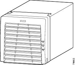
This section describes how to install the AC power shelf (see Figure 1) in a rack and connect it to your power supplies. You can install one or two 2500 W power supplies (see Figure 2) in the AC power shelf, depending on how much power is required.
WarningRead the installation instructions before connecting the system to the power source. Statement 1004
WarningOnly trained and qualified personnel should be allowed to install, replace, or service this equipment. Statement 1030
WarningThis unit is intended for installation in restricted access areas. A restricted access area can be accessed only through the use of a special tool, lock and key, or other means of security. Statement 1017
WarningThis equipment must be grounded. Never defeat the ground conductor or operate the equipment in the absence of a suitably installed ground conductor. Contact the appropriate electrical inspection authority or an electrician if you are uncertain that suitable grounding is available. Statement 1024
WarningThe plug-socket combination must be accessible at all times, because it serves as the main disconnecting device. Statement 1019
WarningBefore working on equipment that is connected to power lines, remove jewelry (including rings, necklaces, and watches). Metal objects will heat up when connected to power and ground and can cause serious burns or weld the metal object to the terminals. Statement 43
WarningUltimate disposal of this product should be handled according to all national laws and regulations. Statement 1040
Figure 1 AC Power Shelf
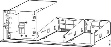
Figure 2 2500 W AC Power Supply
Required Tools
You will need the following tools to perform the procedures in this section:
•
Number 1 and number 2 Phillips screwdrivers to tighten the captive installation screws on most systems
•
3/16-inch flat-blade screwdriver to open the power supply release mechanism and for the captive installation screws on the supervisor engine and switching modules on some systems
•
Antistatic mat or antistatic foam in case you need to remove switching modules to troubleshoot the installation
•
Rack-mount kit
•
Tape measure
•
Level
•
Your own electrostatic discharge (ESD) grounding strap or the disposable ESD strap included with the system
•
11 mm or 7/16 inch wrench or socket for the output terminal nuts
•
Torque wrench and 11 mm or 7/16 inch socket (if you will be installing a strapping kit)
Rack-Mounting and Connecting the AC Power Shelf
Warning
To prevent bodily injury when mounting or servicing this unit in a rack, you must take special precautions to ensure that the system remains stable. The following guidelines are provided to ensure your safety:
•
This unit should be mounted at the bottom of the rack if it is the only unit in the rack.
•
When mounting this unit in a partially filled rack, load the rack from the bottom to the top with the heaviest component at the bottom of the rack.
•
If the rack is provided with stabilizing devices, install the stabilizers before mounting or servicing the unit in the rack. Statement 1006

Note
Install your AC power shelf close enough to your Catalyst 4500 series switch so that you can connect the power cable to the switch. It is recommended that you install the AC power shelf directly above your Catalyst 4500 series switch or in a directly adjacent rack.
To mount the AC power shelf on an equipment rack and connect it to your switch, follow these steps:
Step 1
Align the mounting holes of the L brackets with the mounting holes of the equipment rack.
Step 2
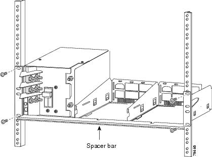
Secure the AC power shelf using four (two per side) 12-24 x 3/4-inch screws through the elongated holes in the L bracket and into the threaded holes in the mounting post. (See Figure 3.)
Figure 3 Mounting the AC Power Shelf on the Rack
Step 3
Using a tape measure and a level, ensure that the AC power shelf is mounted straight and level.
Step 4
Remove the spacer bar.
Step 5
If installing a second shelf in parallel, refer to the "Installing a Second Shelf" section.
Step 6
Make sure that the power switch on the output panel is off.
Step 7
Using the CAB-4502-DC-2M or CAB-4502-DC-60CM cable set, connect the ground and power terminals on the shelf to the DC input terminals on the switch.
Step 8
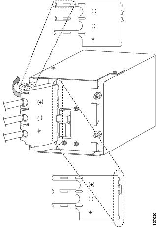
Install the service access cover (WS-X4500-PS01) over the DC terminals on the power shelf as described in the following sub steps:
a.
Insert the tabs on the service access cover into the slots to the left of the terminals.
b.
Bend the service access cover around the terminal block, allowing the corners to poke through the slots on the cover.
Figure 4 Installing the Service Access Cover
c.
Insert the tabs on the front of the service access cover into the slots to the right of the terminals.

CautionTurn off the Catalyst 4500 series switch and unplug the power cord or cords providing AC input power before removing or replacing the service access cover.
WarningThis product must be connected to a power-over-ethernet (PoE) IEEE 802.3af compliant power source or an IEC60950 compliant limited power source. Statement 353
Step 9
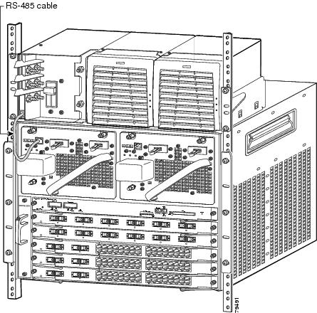
Connect the RS-485 cable (straight-through CAT5 cable commonly used in Ethernet connections) from an RJ-45 connector on the AC power shelf output panel to the RJ-45 connector on the DC-input power supply in your Catalyst 4500 series switch. (See Figure 5.)
Figure 5 Connecting the RJ-485 Cable
Step 10
Install the power supplies. Refer to the "Installing a Power Supply" section.
Step 11
Power on the power switch on the AC power shelf output panel.
Installing a Power Supply
You can install one or two power supplies into the AC power shelf. There are two slots to the right of the output panel as shown in Figure 1.

Note
Do not install the power supplies until the shelf is mounted in the rack.
To install a power supply in an AC power shelf, follow these steps:
Step 1
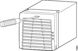
Use a flat-blade screwdriver to unlatch the power supply frame as shown in Figure 6.
Figure 6 Using a Screwdriver to Unlatch the Front Panel of the Power Supply
Step 2
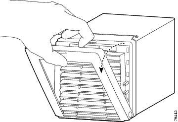
Pull the power supply frame downward as shown in Figure 7.
Figure 7 Pulling the Power Supply Frame Downward
Step 3
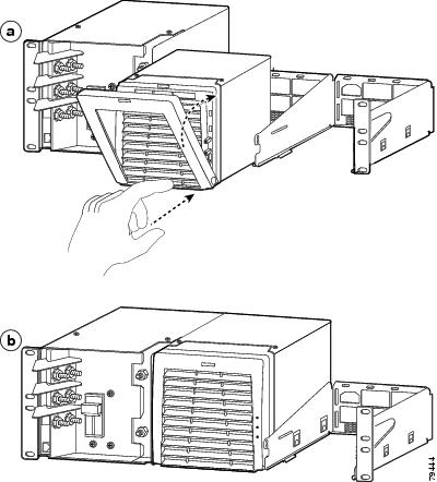
Align the power supply in a AC power shelf slot and gently slide it into the slot as described in the following substeps:
a.
Make sure the hinges on the bottom of the power supply frame connect with the arc-shaped slots on the frame of the voice power module.
b.
Slide the power supply into the slot, making sure that the frame closes completely and the latch clicks into the closed position as shown in Figure 8.
Figure 8 Sliding the Power Supply into the AC Power Shelf Slot
Step 4
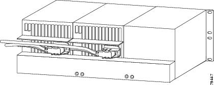
Plug one power cord (250 V, 20 A [U.S.A.]) into each installed power supply as shown in Figure 9. The power connector is on the back of the power supply.
Figure 9 Plugging in the Power Cords
Installing a Second Shelf
Two voice power shelves can be connected in parallel to provide power to a Catalyst 4500 series switch. This will require a strapping kit, which can be ordered separately. To connect the shelves, follow these steps:
Step 1
Install the first shelf as described in Steps 1-4 of the "Rack-Mounting and Connecting the AC Power Shelf" section.
Step 2
If the power supplies are already installed in the first shelf, disconnect the AC power cord from each power supply or remove the power supplies from the shelf. Turning the power supply off does not disable power from the power terminals.
WarningThis unit might have more than one power supply connection. All connections must be removed to de-energize the unit. Statement 1028
Step 3
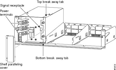
Using a pair of pliers, remove the breakaway tab on the top of the output panel of the AC power shelf you just installed, and remove the breakaway tab on the bottom of the output panel of the secondary AC power shelf.
Figure 10 Locating the Breakaway Tabs
Step 4
Install the second shelf in the rack. Do not leave a gap between the shelves, install the second shelf directly on top of the first.
Step 5
Remove the shelf paralleling cover from both shelves using a Phillips screwdriver.
Step 6
Remove the nuts on the power terminals using an 11-millimeter or 7/16-inch wrench.
Step 7
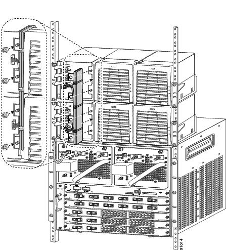
Attach the strapping kit tabs to the power terminals.
Figure 11 Attaching the Strapping Kit
Step 8
Replace and tighten down the nuts removed in Step 5. Do not tighten more than 65 inch pounds
(7 Newton meters).Step 9
Connect the wires attached to the strapping assembly to the signalling ports on both shelves.
WarningThis product must be connected to a power-over-ethernet (PoE) IEEE 802.3af compliant power source or an IEC60950 compliant limited power source. Statement 353
Step 10
Replace the shelf paralleling covers on both shelves.
Step 11
Attach the current and ground connectors as described in Step 6 to Step 8 of the "Installing the AC Power Shelf" section
Specifications
Table 1 AC Power Shelf Specifications
AC-input type
Autoranging input with power factor corrector
AC-input voltage
200 to 240 VAC (±10% for full range)
AC-input current per power supply
15 A maximum at 200 VAC
AC-input frequency
50/60 Hz (nominal) (±3% for full range)
Output capacity per power supply
2600 W maximum
Output holdup time
20 ms minimum
Power shelf weight
41.9 lb (19 kg)
Power shelf dimensions
height 5.13 in. (130 mm)
width 17.4 in. (423 mm)
length 12 in. (304 mm)Power supply weight
9.4 lbs (4.3 kg)
Power supply dimensions
height 5.13 in. (130 mm)
width 5.75 in. (146.1 mm)
length 10.77 in. (273.6 mm)
Related Documentation
For more detailed installation and configuration information, refer to the following documentation:
•
Catalyst 4000 Series Installation Guide
•
Catalyst 4500 Series Installation Guide
•
Catalyst 4000 Series Module Installation Guide
•
Regulatory Compliance and Safety Information for the Catalyst 4500 Series Switches
•
Software Configuration Guide—Catalyst 4000 Family, Catalyst 2948G, and Catalyst 2980G Switches
•
Command Reference—Catalyst 4000 Family, Catalyst 2948G, and Catalyst 2980G Switches
•
System Message Guide—Catalyst 6000 Family, Catalyst 5000 Family, Catalyst 4000 Family, Catalyst 2926G Series, Catalyst 2948G, and Catalyst 2980G Switches
Obtaining Documentation and Submitting a Service Request
For information on obtaining documentation, submitting a service request, and gathering additional information, see the monthly What's New in Cisco Product Documentation, which also lists all new and revised Cisco technical documentation, at:
http://www.cisco.com/en/US/docs/general/whatsnew/whatsnew.html
Subscribe to the What's New in Cisco Product Documentation as a Really Simple Syndication (RSS) feed and set content to be delivered directly to your desktop using a reader application. The RSS feeds are a free service and Cisco currently supports RSS version 2.0.
CCSP, CCVP, the Cisco Square Bridge logo, Follow Me Browsing, and StackWise are trademarks of Cisco Systems, Inc.; Changing the Way We Work, Live, Play, and Learn, and iQuick Study are service marks of Cisco Systems, Inc.; and Access Registrar, Aironet, ASIST, BPX, Catalyst, CCDA, CCDP, CCIE, CCIP, CCNA, CCNP, Cisco, the Cisco Certified Internetwork Expert logo, Cisco IOS, Cisco Press, Cisco Systems, Cisco Systems Capital, the Cisco Systems logo, Cisco Unity, Empowering the Internet Generation, Enterprise/Solver, EtherChannel, EtherFast, EtherSwitch, Fast Step, FormShare, GigaDrive, GigaStack, HomeLink, Internet Quotient, IOS, IP/TV, iQ Expertise, the iQ logo, iQ Net Readiness Scorecard, LightStream, Linksys, MeetingPlace, MGX, the Networkers logo, Networking Academy, Network Registrar, Packet, PIX, Post-Routing, Pre-Routing, ProConnect, RateMUX, ScriptShare, SlideCast, SMARTnet, StrataView Plus, TeleRouter, The Fastest Way to Increase Your Internet Quotient, and TransPath are registered trademarks of Cisco Systems, Inc. and/or its affiliates in the United States and certain other countries.
All other trademarks mentioned in this document or Website are the property of their respective owners. The use of the word partner does not imply a partnership relationship between Cisco and any other company. (0502R)
Copyright © 2004-2005 Cisco Systems, Inc. All rights reserved.
Contact Cisco
- Open a Support Case

- (Requires a Cisco Service Contract)


 Feedback