Catalyst 6000 Family Supervisor Engine 2 DRAM Upgrade Installation Note
Available Languages
Table Of Contents
Catalyst 6000 Family Supervisor Engine 2 DRAM Upgrade Installation Note
Verifying the Memory Configuration on the Supervisor Engine 2
Obtaining Documentation and Submitting a Service Request
Catalyst 6000 Family Supervisor Engine 2 DRAM Upgrade Installation Note
Part Number: MEM-S2-256MB=
This publication describes how to remove and install the synchronous dynamic random-access memory (DRAM) dual inline memory module (DIMM) on the Catalyst 6000 family Supervisor Engine 2 (WS-X6K-S2-MSFC2).
This installation upgrades the total DRAM from 128 MB to 256 MB.

CautionThe supervisor engine is a required system component. If only one supervisor engine is present, removing it while the system is operating causes the system to halt.
Contents
This publication consists of these sections:
•
Verifying the Memory Configuration on the Supervisor Engine 2
•
Obtaining Documentation and Submitting a Service Request
Safety Overview
Safety warnings appear throughout this publication in procedures that may harm you if performed incorrectly. A warning symbol precedes each warning statement.

Warning
Only trained and qualified personnel should be allowed to install or replace this equipment.
Verifying the Memory Configuration on the Supervisor Engine 2
To verify the amount of memory installed on the Supervisor Engine 2, do one of the following:
•
On systems running Catalyst software, enter the show version mod command. The total memory is shown under the DRAM Total column.
This example shows how to check the total memory on the Supervisor Engine 2 in slot 2:
Console> show version 2...<output truncated>DRAM FLASH NVRAMModule Total Used Free Total Used Free Total Used Free------ ------- ------- ------- ------- ------- ------- ----- ----- -----2 130944K 57916K 73028K 16384K 12003K 4381K 512K 257K 255KUptime is 0 day, 0 hour, 34 minutesConsole>In this example, the total memory is 128 MB.
•
On systems running Cisco IOS software, enter the remote command switch show version command. Combine the used memory and free memory to get the total memory.
This example shows how to check the total memory on the Supervisor Engine 2:
Router> remote command switch show version...<output truncated>cisco 6000 (NMP150) processor with 49152K/16384K bytes of memory....<output truncated>Router>In this example, the total memory is 64 MB.
Required Tools
These tools are required to upgrade the Supervisor Engine 2 DRAM:
•
Antistatic mat or foam pad to support the removed Supervisor Engine 2
•
3/16-inch flat-blade screwdriver for the captive installation screws on the Supervisor Engine 2
•
Number 1 Phillips screwdriver for the screws and cap nut that fasten the MSFC2 to the supervisor engine
•
Your own ESD-prevention equipment or the disposable grounding wrist strap included with all upgrade kits, field-replaceable units (FRUs), and spares
Refer to the Site Preparation and Safety Guide for ESD details including the locations of the ESD connectors on the Catalyst 6000 family switches.
Removing the MSFC2

CautionAlways use an ESD wrist strap when handling modules or coming into contact with internal components.
Before you remove the Supervisor Engine 2, you should first upload the current configuration to a server. This saves time when bringing the module back online. You can recover the configuration by downloading it from the server to the nonvolatile memory of the Supervisor Engine 2. For more information, refer to Chapter 26, "Working with Configuration Files," in the Catalyst 6000 Family Software Configuration Guide.
The DRAM DIMM is located beneath the MSFC2. To install the DIMM, you must remove the MSFC2 from the Supervisor Engine 2.

Note
The MSFC2 shipped after November 2001 is physically smaller than the previous MSFC2.
To remove the MSFC2 from the Supervisor Engine 2, follow these steps:
Step 1
Upload the current configuration to a server. On any modules running Cisco IOS software, save the running configuration.
Step 2
Remove the Supervisor Engine 2 from the Catalyst 6000 family switch (refer to the Catalyst 6000 Family Module Installation Guide for removal instructions).
Step 3
Place the Supervisor Engine 2 on an antistatic mat or foam.
Step 4
Remove the securing screws and cap nut that secure the MSFC2 to the Supervisor Engine 2. (See Figure 1 for an MSFC2 shipped before November 2001 or see Figure 2 for an MSFC2 shipped after November 2001.)

Note
The MSFC2 shipped after November 2001 is not secured with a cap nut. (See Figure 2.)
Figure 1 MSFC2 Shipped Before November 2001—Removing Securing Screws and Cap Nut
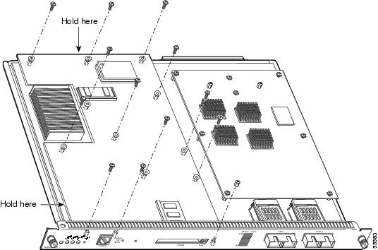
Figure 2 MSFC2 Shipped After November 2001—Removing Securing Screws

Step 5
Hold the top edge of the MSFC2 with your right hand and the bottom-left edge with your left hand. (See Figure 1 for an MSFC2 shipped before November 2001 or Figure 2 for an MSFC2 shipped after November 2001.) Gently lift the MSFC2 with both hands simultaneously and remove the MSFC2 from the Supervisor Engine 2.

CautionUse care not to damage the connectors on the Supervisor Engine 2. If you damage a connector, you will have to return the Supervisor Engine 2 to Cisco for repair.
Step 6
Place the MSFC2 on an antistatic mat or antistatic foam pad.
Proceed to the "Installing the DRAM DIMM" section to install the DRAM.
Installing the DRAM DIMM
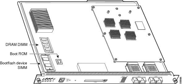
This section describes how to remove the existing DIMM and replace it with the upgrade DIMM. The DRAM DIMM location is shown in Figure 3.
Figure 3 Supervisor Engine 2 DRAM DIMM Location

CautionAlways use an ESD wrist strap when handling modules or coming into contact with internal components.
To install the DRAM upgrade, follow these steps:
Step 1
Remove the DIMM from the socket by pulling the locking spring clips on both sides of the DIMM holder outward and tilt the DIMM free of the clips (see Figure 4). Be careful not to break the clips on the DIMM connector.
Figure 4 Removing the DIMM

Step 2
Hold the DIMM by its edges and gently lift and remove it, placing it on an antistatic mat or foam (see Figure 5).
Figure 5 Handling a DIMM
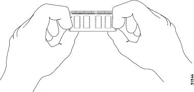

CautionDIMMs are sensitive components that are susceptible to ESD damage. To prevent ESD damage, handle DIMMs by the edges only; avoid touching the memory modules, pins, or traces (the metal fingers along the connector edge of the DIMM). (See Figure 5.)
Step 3
Remove the upgrade DIMM from the antistatic container.
Step 4
Hold the DIMM by its edges (see Figure 5).
Step 5
Tilt the DIMM to approximately the same angle as the socket, and insert the connector edge into the socket.

CautionWhen inserting the DIMM, use firm but not excessive pressure. If you damage a socket, you will have to return the Supervisor Engine 2 to Cisco for repair.
Step 6
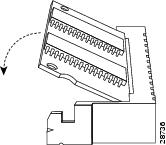
Press the DIMM down until it is secured by the spring clips (see Figure 6).
Figure 6 Installing the DIMM
Step 7
When the DIMM is installed, check the two alignment holes and ensure that the spring retainer is visible. If it is not, the DIMM is not seated properly. If the DIMM appears misaligned, carefully remove it and reseat it in the socket. Push the DIMM firmly back into the socket until the retainer springs snap into place.

Note
If you are upgrading the Supervisor Engine 2 boot ROM and bootflash device, do that now before you reinstall the MSFC2. Refer to the Catalyst 6000 Family Supervisor Engine 2 Boot ROM and Bootflash Device Upgrade Installation Note.
If you are not upgrading the Supervisor Engine 2 boot ROM and bootflash device, or if you have already upgraded the Supervisor Engine 2 boot ROM and bootflash device, see the "Installing the MSFC2" section.
Installing the MSFC2

Note
The MSFC2 shipped after November 2001 is physically smaller than the previous MSFC2.
To install the MSFC2 on the Supervisor Engine 2, follow these steps:
Step 1
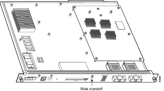
Align the MSFC2 with the standoffs on the Supervisor Engine 2. The MSFC2 shipped before November 2001 will also align with the male standoff. (See Figure 7.) Make sure the remaining mounting holes on the MSFC2 are aligned with the remaining standoffs.
Figure 7 Male Standoff Location on the Supervisor Engine 2
Step 2
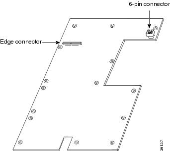
Ensure that the connectors on the MSFC2 (see Figure 8) are aligned with the connectors on the Supervisor Engine 2.
Figure 8 MSFC2 Connectors
Step 3
Carefully seat the MSFC2 onto the Supervisor Engine 2. (See Figure 9 for an MSFC2 shipped before November 2001 or Figure 10 for an MSFC2 shipped after November 2001.)
Step 4
Using your thumbs, apply pressure at the connector locations (shown in Figure 9 for an MSFC2 shipped before November 2001 or Figure 10 for an MSFC2 shipped after November 2001) to ensure the MSFC2 is securely seated on the Supervisor Engine 2.

CautionUse care not to damage the connectors on the Supervisor Engine 2. If you damage a connector, you will have to return the Supervisor Engine 2 to Cisco for repair.
Figure 9 MSFC2 Shipped Before November 2001—Seating on the Supervisor Engine 2
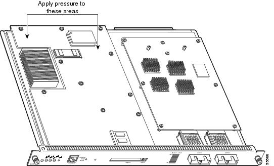
Figure 10 MSFC2 Shipped After November 2001—Seating on the Supervisor Engine 2


CautionEnsure that the MSFC2 is securely seated before you install and tighten the securing screws. Using the screws to seat the MSFC2 could warp the card.
Step 5
Use a Phillips-head screwdriver to install the screws and cap nut (if applicable) that secure the MSFC2 to the Supervisor Engine 2. (See Figure 11 for an MSFC2 shipped before November 2001 or Figure 12 for an MSFC2 shipped after November 2001.)

CautionYou must install the cap nut (if applicable) and all screws. The screws provide grounding between the MSFC2 and the Supervisor Engine 2. Failure to install the cap nut and all screws will invalidate the safety approvals and can cause fire and electrical hazards.
Figure 11 MSFC2 Shipped Before November 2001—Installing the Securing Screws and Cap Nut
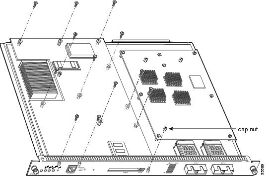
Figure 12 MSFC2 Shipped After November 2001—Installing the Securing Screws

Step 6
Install the Supervisor Engine 2 in the Catalyst 6000 family switch (refer to the Catalyst 6000 Family Module Installation Guide for installation instructions).
If you have redundant supervisor engines, go to Step 2 in the "Removing the MSFC2" section and follow the directions to upgrade the DRAM on the redundant supervisor engine.
Step 7
Enter the show version mod command to verify the amount of memory on the Supervisor Engine 2.
Related Documentation
For additional information on Catalyst 6000 family switches and command-line interface (CLI) commands, refer to the following publications:
•
Regulatory Compliance and Safety Information for the Catalyst 6000 Family Switches
•
Catalyst 6000 Family Supervisor Engine 2 Boot ROM and Flash Upgrade Installation Note
•
Catalyst 6000 Family Installation Guide
•
Catalyst 6000 Family Module Installation Guide
•
Catalyst 6000 Family Software Configuration Guide
•
Catalyst 6000 Family Command Reference
•
Catalyst 6000 Family IOS Software Configuration Guide
•
Catalyst 6000 Family IOS Command Reference
•
Site Preparation and Safety Guide
Obtaining Documentation and Submitting a Service Request
For information on obtaining documentation, submitting a service request, and gathering additional information, see the monthly What's New in Cisco Product Documentation, which also lists all new and revised Cisco technical documentation, at:
http://www.cisco.com/en/US/docs/general/whatsnew/whatsnew.html
Subscribe to the What's New in Cisco Product Documentation as a Really Simple Syndication (RSS) feed and set content to be delivered directly to your desktop using a reader application. The RSS feeds are a free service and Cisco currently supports RSS Version 2.0.

 Feedback