-
Cisco CallManager System Guide, Release 4.1(3)
-
Index
-
Preface
-
Introduction
-
Cisco IP Telephony Overview
-
System Configuration Overview
-
Multilevel Administration Access
-
System-Level Configuration Settings
-
Clustering
-
Redundancy
-
Call Admission Control
-
Cisco TFTP
-
Device Support
-
Services
-
Auto-Registration
-
Partitions and Calling Search Spaces
-
Time-of-Day Routing
-
Understanding Route Plans
-
Application Dial Rules Overview
-
Understanding the Directory
-
Managing User Directory Information
-
Media Resource Management
-
Annunciator
-
Conference Bridges
-
Transcoders
-
Music On Hold
-
Media Termination Points
-
Cisco DSP Resources for Transcoding, Conferencing, and MTP
-
Voice Mail Connectivity to Cisco CallManager
-
SMDI Voice Mail Integration
-
Cisco Unity Messaging Integration
-
Cisco DPA Integration
-
Call Park
-
Call Pickup and Group Call Pickup
-
Cisco IP Phone Services
-
Cisco CallManager Extension Mobility and Phone Login Features
-
Cisco CallManager Attendant Console
-
Cisco IP Manager Assistant
-
Understanding Cisco CallManager Voice Gateways
-
Understanding IP Telephony Protocols
-
Understanding Session Initiation Protocol (SIP)
-
Understanding Cisco CallManager Trunk Types
-
Cisco IP Phones
-
Understanding Video Telephony
-
Computer Telephony Integration
-
Cisco ATA 186 and Cisco ATA 188
-
Administrative Tools Overview
-
Administrative Accounts and Passwords
-
 Feedback
Table Of Contents
Understanding Cisco CallManager Voice Gateways
Cisco Access Digital Trunk Gateways DT-24+/DE-30+
Cisco Access Analog Station Gateways
Cisco VG248 Analog Phone Gateway
Cisco VG224 Analog Phone Gateway
Cisco IAD2400 Series Integrated Access Device
Cisco Catalyst 4000 and 6000 Voice Gateway Modules
Cisco Catalyst 6000 8 Port Voice T1/E1 and Services Module
Cisco Catalyst 6000 24 Port FXS Analog Interface Module
Cisco Communication Media Module
Cisco Catalyst 4000 Access Gateway Module
Cisco Catalyst 4224 Access Gateway Switch
Outbound FastStart Call Connections
Gateways, Dial Plans, and Route Groups
Dependency Records for Gateways and their Route Groups and Directory Numbers
Cisco VG248 Analog Phone Gateway
Transferring Calls Between Gateways
Configuring Transfer Capabilities Using Gateway Configuration
Configuring Transfer Capabilities by Using Call Classification Service Parameter
Blocking Transfer Capabilities by Using Service Parameters
Gateway Configuration Checklist
MGCP BRI Gateway Configuration Checklist
Where to Find More Information
Understanding Cisco CallManager Voice Gateways
Cisco IP telephony gateways enable Cisco CallManager to communicate with non-IP telecommunications devices. Cisco CallManager supports several types of voice gateways.
This section covers the following topics:
•
Gateways, Dial Plans, and Route Groups
•
•
•
Cisco Voice Gateways
Cisco CallManager supports several types of Cisco IP telephony gateways. Gateways use call control protocols to communicate with the PSTN and other non-IP telecommunications devices, such as private branch exchanges (PBXs).
Trunk interfaces specify how the gateway communicates with the PSTN or other external devices by using time-division multiplexing (TDM) signaling. Cisco CallManager and Cisco gateways use a variety of TDM interfaces, but supported TDM interfaces vary by gateway model. Refer to the Cisco IP Telephony Solutions Reference Network Design Guide for more information about selecting and configuring gateways. The following list gives available interfaces that Cisco CallManager supports:
•
•
•
•
•
•
•
Cisco CallManager can use H.323 gateways that support E1 CAS, but you must configure the E1 CAS interface on the gateway.
For information about IP telephony protocols, see the "Understanding IP Telephony Protocols" chapter.
These sections provide an overview of the following gateways that Cisco CallManager supports:
•
Standalone Voice Gateways
This section describes these standalone, application-specific gateway models that are supported for use with Cisco CallManager.
Cisco Voice Gateway 200
The Cisco IP Telephony Voice Gateway (VG200) provides a 10/100BaseT Ethernet port for connection to the data network. The following list gives available telephony connections:
•
•
•
•
•
–
–
The MGCP VG200 integration with legacy voice-messaging systems allows the Cisco CallManager to associate a port with a voice mailbox and connection.
Cisco Access Digital Trunk Gateways DT-24+/DE-30+
The Cisco Access Digital Trunk Gateways DT-24+/DE-30+ provide the following features:
•
•
•
•
Cisco Access Analog Station Gateways
Station gateways let you connect the Cisco CallManager to POTS analog telephones, interactive voice response (IVR) systems, fax machines, and voice-messaging systems. Station gateways provide FXS ports. The AS-2, AS-4, and AS-8 models accommodate two, four, and eight Voice over IP (VoIP) gateway channels, respectively.
Cisco Access AS gateways communicate with Cisco CallManager by using Skinny Gateway Protocol.
Cisco Analog Trunk Gateways
Analog trunk gateways let you connect Cisco CallManager to standard PSTN central office (CO) or PBX trunks. Trunk gateways provide FXO ports. The AT-2, AT-4, and AT-8 models accommodate two, four, and eight VoIP gateway channels. The signaling type specifies loop start.
Cisco Access AT gateways communicate with Cisco CallManager by using Skinny Gateway Protocol.
Cisco VG248 Analog Phone Gateway
The Cisco VG248 Analog Phone Gateway has a standalone, 19-inch rack-mounted chassis with 48-FXS ports. This product allows on-premise analog telephones, fax machines, modems, voice-messaging systems, and speakerphones to register with a single Cisco CallManager cluster.
Cisco VG248 Analog Phone Connectivity
The Cisco VG248 Analog Phone Gateway communicates with Cisco CallManager by using the Skinny Client Control Protocol to allow support for the following supplementary services features for analog phones:
•
•
•
•
•
•
•
•
•
•
•
•
•
Cisco VGC Phone Device Types
All Cisco VG248 ports and units appear as distinct devices in Cisco CallManager with the device type "Cisco VGC Phone." Cisco CallManager recognizes and configures each port as a phone.
Fax and Modem Connectivity
The Cisco VG248 supports legacy fax machines and modems. When using fax machines, the Cisco VG248 uses either the Cisco fax relay or pass-through/up speed technology to transfer faxes across the network with high reliability.
You can connect any modem to the Cisco VG248 by using pass-through mode.
Voice-Mail Connectivity
The Cisco VG248 generates call information by using the Simplified Message Desk Interface (SMDI) format for all calls that are ringing on any of the 48 analog lines that connect to it. It will also pass on SMDI call information from other Cisco VG248s, or from a legacy PBX, to the voice-messaging system. Any commands for message-waiting indicators get sent to Cisco CallManager and to any other attached SMDI hosts.
This mechanism allows for many new configurations when SMDI-based voice-messaging systems are used, including
•
•
•
•
Cisco VG248 Time Device
The Cisco VG248 contains a real-time clock that is persistent across power cycles and restarts. The real-time clock gets set for the first time when the device registers with Cisco CallManager. The clock gets set by using the DefineDateTime Skinny message that Cisco CallManager sends. After a power cycle or restart, the clock resets when the Cisco VG248 receives the DefineDateTime message from Cisco CallManager and then resets no more than once per hour thereafter.
Cisco VG248 Configuration File Updates
The Cisco VG248 queries the TFTP server to access the configuration files for the device. The configuration files update whenever you modify the configuration of the Cisco VG248 via Cisco CallManager.
Refer to the Gateway Configuration section and the Cisco IP Phone Configuration section of the Cisco CallManager Administration Guide and to the Cisco VG248 Analog Phone Gateway Software Configuration Guide for more information.
Cisco VG224 Analog Phone Gateway
The Cisco VG224 Analog Phone Gateway has a standalone, 17-inch rack-mounted chassis with 24-FXS ports. This product allows on-premise analog telephones, fax machines, modems, and speakerphones to register with Cisco CallManager.
Cisco IAD2400 Series Integrated Access Device
The Cisco IAD2420 integrated access device provides voice, data, and video services over internet protocol (IP) and asynchronous transfer mode (ATM) networks. By using the Cisco IAD 2420, service providers can deliver toll-quality voice and data services over circuit- or packet-switched networks. The Cisco IAD2420 provides an MGCP interface with Cisco CallManager and supports the following capabilities:
•
•
MGCP BRI Call Connections
Previously, gateways used H.323 signaling to Cisco CallManager to provide interfaces to the public switched telephone network (PSTN) for BRI ISDN connections. The following list gives drawbacks to using the H.323 protocol:
•
•
•
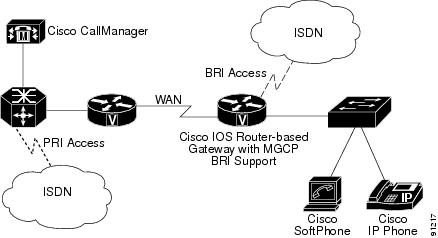
Now, Cisco CallManager can use a Media Gateway Control Protocol (MGCP) gateway to handle BRI ISDN connections to the PSTN and to provide a centrally administered gateway interface. Cisco CallManager uses logical connections to exchange MGCP and ISDN Q.931 messages with the gateway. This connection uses a User Datagram Protocol (UDP) logical connection for exchanging MGCP messages and a Transmission Control Protocol (TCP) connection for the backhaul ISDN Q.931 messages.
Figure 36-1 shows a typical scenario that centralizes call processing for remote-site BRI trunk gateways that connect to the PSTN. When a call arrives from or goes to the PSTN over the BRI trunk, the Cisco CallManager and the gateway (based on an IOS router) exchange ISDN Q.931 messages across the WAN.
Figure 36-1 Topology Shows a Scenario by Using MGCP BRI Interfaces
For more information about MGCP BRI with Cisco CallManager, refer to the MGCP-Controlled Backhaul of BRI Signaling in Conjunction with Cisco CallManager document on the Cisco.com website.
Note
Cisco Catalyst 4000 and 6000 Voice Gateway Modules
Several telephony modules for the Cisco Catalyst 4000 and 6000 family switches act as telephony gateways. You can use existing Cisco Catalyst 4000 or 6000 family devices to implement IP telephony in your network by using the following voice gateway modules:
•
•
Cisco Catalyst 6000 8 Port Voice T1/E1 and Services Module
The Cisco Catalyst 6000 8 Port Voice T1/E1 and Services Modules provide the following features:
•
–
–
•
•
Users have the flexibility to use ports on a T1 module for T1 connections or as network resources for voice services. Similarly, the E1 module provides ports for E1 connections or as network resources. The ports can serve as T1/E1 interfaces, or the ports will support transcoding or conferencing.
Note
Similar to the Cisco MGCP-controlled gateways with FXS ports, the Cisco 6608 T1 CAS gateway supports hookflash transfer. Hookflash transfer defines a signaling procedure that allows a device, such as a voice-messaging system, to transfer to another destination. While the device is connected to Cisco CallManager through a T1 CAS gateway, the device performs a hookflash procedure to transfer the call to another destination. Cisco CallManager responds to the hookflash by using a blind transfer to move the call. When the call transfer completes, the voice channel that connected the original call to the device gets released.
Note
Cisco Catalyst 6000 24 Port FXS Analog Interface Module
The Cisco Catalyst 6000 24 Port FXS Analog Interface Module provides the following features:
•
•
•
•
The Catalyst 6000 24 Port FXS Analog Interface Module provides 24 FXS ports for connecting to analog phones, conference room speakerphones, and fax machines. You can also connect to legacy voice-messaging systems by using SMDI and by associating the ports with voice-messaging extensions.
The FXS module provides legacy analog devices with connectivity into the IP network. Analog devices can use the IP network infrastructure for toll-bypass applications and to communicate with devices such as SCCP IP phones and H.323 end stations. The FXS module also supports fax relay, which enables compressed fax transmission over the IP WAN and preserves valuable WAN bandwidth for other data applications.
Cisco Communication Media Module
The Cisco Communication Media Module (CMM), which is a Catalyst 6500 line card, provides T1 and E1 gateways that allow organizations to connect their existing TDM network to their IP communications network. The Cisco CMM provides connectivity to the PSTN also. You can configure the Cisco CMM, which provides an MGCP interface to Cisco CallManager, with the following interface and service modules:
•
•
•
Cisco Catalyst 4000 Access Gateway Module
The Cisco Catalyst 4000 Access Gateway Module provides an MGCP or H.323 gateway interface to Cisco CallManager. You can configure this module with the following interface and service modules:
•
•
Cisco Catalyst 4224 Access Gateway Switch
The Cisco Catalyst 4224 Access Gateway Switch provides a single-box solution for small branch offices. The Catalyst 4224 provides switching, IP routing, and PSTN voice-gateway services by using onboard digital signal processors (DSPs). The Catalyst 4224 has four slots that you can configure with multiflex voice and WAN interface cards to provide up to 24 ports. These ports can support the following voice capabilities:
•
•
•
The Cisco Catalyst 4224 Access Gateway Switch provides an MGCP or H.323 interface to Cisco CallManager.
H.323 Gateways
H.323 devices comply with the H.323 communications standards and enable video conferencing over LANs and other packet-switched networks. You can add third-party H.323 devices or other Cisco devices that support H.323 (such as the Cisco 2600 series, 3600 series, or 5300 series gateways).
Cisco IOS H.323 Gateways
Cisco IOS H.323 gateways such as the Cisco 2600, 3600, 1751, 1760, 3810 V3, 7200 7500, AS5300, and VG200 provide full-featured routing capabilities. Refer to the documentation for each of these gateway types for information about supported voice gateway features and configuration.
T.38 Fax Relay
Transporting real-time Group 3 fax documents over internet protocol (IP) uses the International Telecommunications Union Telecommunication Standardization Sector (ITU-T) recommendation T.38 Fax Relay. The T.38 standard defines the IP network protocol that Internet-aware T.38 fax devices and T.38 IP fax gateways use. The T.38 Fax Relay for VoIP H.323 feature provides standards-based, fax relay protocol support for Cisco and other vendor gateways.
The T.38 Fax Relay feature provides a standards-based, fax relay protocol that is available on several Cisco gateways. Because the T.38 Fax Relay protocol is standards based, Cisco gateways and gatekeepers can interoperate with third-party T.38 enabled gateways and gatekeepers in a mixed vendor network that requires real-time fax relay capabilities.
Cisco CallManager handles the T.38 fax call by using a voice connection. When the originating gateway sends a fax, the gateway establishes an initial voice call. The terminating gateway detects the fax tone that the answering fax machine generates. The VoIP H.323 call stack then starts a T.38 mode request by using H.245 procedures. If the opposite end of the call acknowledges the T.38 mode request, the initial audio channel closes, and T.38 Fax Relay channel opens. When the fax transmission finishes, the call disconnects.
Outbound FastStart Call Connections
Calls that are placed from IP phones over large WAN topologies can experience voice clipping when the called party goes off hook to answer the call. When H.323 trunks or gateways are separated from the Cisco CallManager server, significant delays can occur because of the many H.245 messages that are exchanged when a call is set up.
With the FastStart feature, information that is required to complete a media connection between two parties gets exchanged during the H.225 portion of call setup, and this exchange eliminates the need for H.245 messages. The connection experiences one roundtrip WAN delay during call setup, and the calling party does not receive voice clipping when the called party answers the call.
Cisco CallManager uses media termination points (MTP) for making an H.323 outbound FastStart call. Cisco CallManager starts an outbound FastStart call by allocating an MTP and opening the receive channel. Next, the H.323 Fast Connect procedure sends the SETUP message with a FastStart element to the called endpoint. The FastStart element includes information about the receiving channel for the MTP.
The called endpoint accepts the H.323 Fast Connect procedure by sending a CALL PROCEEDING, PROGRESS, ALERT, or CONNECT message that contains a FastStart element. When Cisco CallManager receives the FastStart element, it connects the media immediately and avoids the delays with the usual exchange of H.245 messages.
The called endpoint can refuse the H.323 Fast Connect procedure by not returning the FastStart element in any of the messages up to and including the CONNECT message. In this case, the Cisco CallManager handles the call as a normal call and uses the MTP for subsequent media cut-through.
Note
The Outbound FastStart feature requires an MTP. If an MTP is not available when the call is set up, the call continues without FastStart and with no supplementary services. If you want all calls to use FastStart only, you can set the service parameter called "Fail call if MTP allocation fails," which is located under Cluster Wide Parameters (Device-H323). When you set this parameter to True, the system rejects calls when no MTP is available.
Related Topic
H.323 Gateway Configuration Settings, Cisco CallManager Administration Guide
Voice Gateway Model Summary
Table 36-1 summarizes Cisco voice gateways that Cisco CallManager supports with information about the gateway control protocols, trunk interfaces, and port types.
Gateways, Dial Plans, and Route Groups
Gateways use dial plans to access or call out to the PSTN, route groups, and group-specific gateways. The different gateways that are used within the Cisco IP Telephony Solutions have dial plans that are configured in different places:
•
•
The route group points to one or more gateways and can choose the gateways for call routing based on preference. The route group can serve as a trunk group by directing all calls to the primary device and then using the secondary devices when the primary is unavailable. One or more route lists can point to the same route group.
All devices in a given route group share the same characteristics such as path and digit manipulation. Cisco CallManager restricts the gateways that you can include in the same route group and the route groups that you can include in the same route list. For more information about routing, see the "Route Plan Overview" section.
Route groups can perform digit manipulation that will override what was performed in the route pattern. Configuration information that is associated with the gateway defines how the call is actually placed and can override what was configured in the route pattern.
You can configure H.323 trunks, not H.323gateways, to be gatekeeper-controlled trunks. This means that before a call is placed to an H.323 device, it must successfully query the gatekeeper. See the "Gatekeeper and Trunk Configuration in Cisco CallManager" section for more information.
Multiple clusters for inbound and outbound calls can share H.323 trunks, but MGCP and Skinny-based gateways remain dedicated to a single Cisco CallManager cluster.
Related Topics
•
Dependency Records for Gateways and their Route Groups and Directory Numbers
To find route groups or directory numbers that a specific gateway or gateway port is using, click the Dependency Records link that is provided on the Cisco CallManager Administration Gateway Configuration window. The Dependency Records Summary window displays information about route groups and directory numbers that are using the gateway or port. To find out more information about the route group or directory number, click the route group or directory number, and the Dependency Records Details window displays. If the dependency records are not enabled for the system, the dependency records summary window displays a message.
For more information about Dependency Records, refer to Accessing Dependency Records, Deleting Gateways, and Removing a Directory Number from a Phone in the Cisco CallManager Administration Guide.
•
Gateway Failover and Fallback
This section describes how these Cisco voice gateways handle Cisco CallManager failover and fallback situations.
•
MGCP Gateways
To handle Cisco CallManager failover situations, MGCP gateways receive a list of Cisco CallManagers that is arranged according to the Cisco CallManager group and defined for the device pool that is assigned to the gateway. A Cisco CallManager group can contain one, two, or three Cisco CallManagers that are listed in priority order for the gateway to use. If the primary Cisco CallManager in the list fails, the secondary Cisco CallManager gets used. If the primary and secondary Cisco CallManagers fail, the tertiary Cisco CallManager gets used.
Fallback describes the process of recovering a higher priority Cisco CallManager when a gateway fails over to a secondary or tertiary Cisco CallManager. Cisco MGCP gateways periodically take status of higher priority Cisco CallManagers. When a higher priority Cisco CallManager is ready, it gets marked as available again. The gateway reverts to the highest available Cisco CallManager when all calls go idle or within 24 hours, whichever occurs first. The administrator can force a fallback either by stopping the lower priority Cisco CallManager whereby calls get preserved, by restarting the gateway, which preserves calls, or by resetting Cisco CallManager, which terminates calls.
Note
IOS H.323 Gateways
Cisco IOS gateways also handle Cisco CallManager failover situations. By using several enhancements to the dial-peer and voice class commands in Cisco IOS Release 12.1(2)T, Cisco IOS gateways can support redundant Cisco CallManagers. The command, h225 tcp timeout seconds, specifies the time that it takes for the Cisco IOS gateway to establish an H.225 control connection for H.323 call setup. If the Cisco IOS gateway cannot establish an H.225 connection to the primary Cisco CallManager, it tries a second Cisco CallManager that is defined in another dial-peer statement. The Cisco IOS gateway shifts to the dial-peer statement with the next highest preference setting.
The following example shows the configuration for H.323 gateway failover:
interface FastEthernet0/0ip address 10.1.1.10 255.255.255.0dial-peer voice 101 voipdestination-pattern 1111session target ipv4:10.1.1.101preference 0voice class h323 1dial-peer voice 102 voipdestination-pattern 1111session target ipv4:10.1.1.102preference 1voice class h323 1voice class h323 1h225 timeout tcp establish 3
Note
Cisco VG248 Analog Phone Gateway
The Cisco VG248 Analog Phone Gateway supports the Skinny Client Control Protocol for clustering and failover.
Transferring Calls Between Gateways
Using Cisco CallManager Administration, you can configure gateways as OnNet (internal) gateways or OffNet (external) gateways by using Gateway Configuration or by setting a clusterwide service parameter. Used in conjunction with the clusterwide service parameter, Block OffNet to OffNet Transfer, the configuration determines whether calls can be transferred over a gateway.
To use the same gateway to route both OnNet and OffNet calls, associate the gateway with two different route patterns. Make one gateway OnNet and the other OffNet with both having the Allow Device Override check box unchecked.
Configuring Transfer Capabilities Using Gateway Configuration
Using Cisco CallManager Administration Gateway Configuration, you can configure a gateway as OffNet or OnNet. The system considers the calls that come to the network through that gateway OffNet or OnNet, respectively. Use the Gateway Configuration window field, Call Classification, to configure the gateway as OffNet, OnNet, or Use System Default. See Table 36-2 for description of these settings.
The Route Pattern Configuration window provides a drop-down list box called Call Classification, which allows you to configure a route pattern as OffNet or OnNet. When Call Classification is set to OffNet and the Allow Device Override check box is unchecked, the system considers the outgoing calls that use this route pattern as OffNet (if configured as OnNet and check box is unchecked, then outgoing calls are considered OnNet).
The same gateway can be used to route both OnNet and OffNet calls by associating the gateway with two different route patterns: one OnNet and the other OffNet, with both having the Allow Device Override check box unchecked. For outgoing calls, the outgoing device setting classifies the call as either OnNet or OffNet by determining whether the Allow Device Override check box is checked.
In route pattern configuration, if the Call Classification is set as OnNet, the Allow Device Override check box is checked, and the route pattern is associated with an OffNet gateway, the system considers the outgoing call OffNet.
Configuring Transfer Capabilities by Using Call Classification Service Parameter
To configure all gateways to be OffNet (external) or OnNet (internal), perform the following two steps:
1.
2.
Blocking Transfer Capabilities by Using Service Parameters
Block transfer provides a way of restricting transfer between external devices, so fraudulent activity gets prevented. You can configure the following devices as OnNet (internal) or OffNet (external) to Cisco CallManager:
•
•
•
•
•
If you do not want OffNet calls to be transferred to an external device (one that is configured as OffNet), set the Cisco CallManager clusterwide service parameter, Block OffNet to OffNet Transfer, to True.
If a user tries to transfer a call on an OffNet gateway that is configured as blocked, a message displays on the user phone to indicate that the call cannot be transferred.
Related Topics
•
•
•
Gateway Configuration Checklist
Table 36-3 provides an overview of the steps that are required to configure gateways in Cisco CallManager, along with references to related procedures and topics.
Table 36-3 Gateway Configuration Checklist
Step 1
Install and configure the gateway or voice gateway module in the network.
Refer to the installation and configuration documentation for the model of gateway that you are configuring.
Step 2
Gather the information that you need to configure the gateway to operate with Cisco CallManager.
Gateway Configuration Settings, Cisco CallManager Administration Guide
Port Configuration Settings, Cisco CallManager Administration Guide
Step 3
On the gateway, perform any required configuration steps.
Refer to the voice feature software configuration documentation or Cisco IOS documentation for the model of gateway that you are configuring.
Step 4
Add and configure the gateway in Cisco CallManager Administration.
Adding Gateways to Cisco CallManager, Cisco CallManager Administration Guide
Step 5
Add and configure ports on the gateway or
add and configure the Cisco VG248 Analog Phone Gateway.Port Configuration Settings, Cisco CallManager Administration Guide
Adding a Cisco VG248 Analog Phone Gateway, Cisco CallManager Administration Guide
Cisco IP Phone Configuration, Cisco CallManager Administration Guide
Step 6
For FXS ports, add directory numbers, if appropriate.
Adding a Directory Number, Cisco CallManager Administration Guide
Directory Number Configuration Settings, Cisco CallManager Administration Guide
Step 7
Configure the dial plan for the gateway for routing calls out to the PSTN or other destinations.
This configuration can include setting up a route group, route list, and route pattern for the Gateway in Cisco CallManager or, for some gateways, configuring the dial plan on the gateway itself.
Cisco IP Telephony Solution Reference Network Design
Cisco CallManager Administration Guide
Step 8
Reset the gateway to apply the configuration settings.
Resetting and Restarting Gateways, Cisco CallManager Administration Guide
Tip
MGCP BRI Gateway Configuration Checklist
Table 36-4 provides an overview of the steps that are required to configure a BRI gateway in Cisco CallManager, along with references to related procedures and topics.
Table 36-4 MGCP BRI Gateway Configuration Checklist
Step 1
Install and configure the gateway and voice modules in the network.
Refer to the installation and configuration documentation for the model of gateway that you are configuring.
Step 2
Gather the information that you need to configure the gateway to operate with Cisco CallManager and to configure the trunk interface to the PSTN or external non-IP telephony device.
Gateway Configuration Checklist
Adding a BRI Port to an MGCP Gateway, Cisco CallManager Administration Guide
Step 3
On the gateway, perform any required configuration steps.
Refer to the voice feature software configuration documentation or Cisco IOS documentation for the model of gateway that you are configuring.
Step 4
Add and configure the gateway in Cisco CallManager Administration.
Gateway Configuration, Cisco CallManager Administration Guide
Step 5
Add and configure ports on the gateway.
Gateway Configuration, Cisco CallManager Administration Guide
Step 6
Configure the dial plan for the gateway for routing calls out to the PSTN or other destinations.
This configuration can include setting up a route group, route list, and route pattern for the gateway in Cisco CallManager or, for some gateways, configuring the dial plan on the gateway itself.
Cisco CallManager Administration Guide
Cisco IP Telephony Network Design Guide
Step 7
Reset the gateway to apply the configuration settings.
Cisco CallManager Administration Guide
Tip
Where to Find More Information
Related Topics
•
•
•
•
•
•
Additional Cisco Documentation
•
•
•
•
•