Contents
- Mesh Deployment Modes
- Wireless Mesh Network
- Wireless Backhaul
- Universal Access
- Point-to-Multipoint Wireless Bridging
- Point-to-Point Wireless Bridging
- Configuring Mesh Range (CLI)
- Assumptions for the AP1522 Range Calculator
- Assumptions for the AP1552 Range Calculator
Mesh Deployment Modes
This chapter describes the mesh deployment modes and contains the following sections:
- Wireless Mesh Network
- Wireless Backhaul
- Point-to-Multipoint Wireless Bridging
- Point-to-Point Wireless Bridging
Wireless Mesh Network
In a Cisco wireless outdoor mesh network, multiple mesh access points comprise a network that provides secure, scalable outdoor wireless LAN.
The three RAPs are connected to the wired network at each location and are located on the building roof. All the downstream access points operate as MAPs and communicate using wireless links (not shown).
Both MAPs and RAPs can provide WLAN client access; however, the location of RAPs are often not suitable for providing client access. All the three access points in are located on the building roofs and are functioning as RAPs. These RAPs are connected to the network at each location.
Some of the buildings have onsite controllers to terminate CAPWAP sessions from the mesh access points but it is not a mandatory requirement because CAPWAP sessions can be back hauled to a controller over a wide-area network (WAN).
 Note | CAPWAP over CAPWAP is not supported. |
Wireless Backhaul
In a Cisco wireless backhaul network, traffic can be bridged between MAPs and RAPs. This traffic can be from wired devices that are being bridged by the wireless mesh or CAPWAP traffic from the mesh access points. This traffic is always AES encrypted when it crosses a wireless mesh link such as a wireless backhaul.
AES encryption is established as part of the mesh access point neighbor relationship with other mesh access points. The encryption keys used between mesh access points are derived during the EAP authentication process.
Only 5 GHz backhaul is possible on all mesh access points except 1522 in which either 2.4 or 5 GHz radio can be configured as a backhaul radio (see Configuring Advanced Features, page 159).
Universal Access
You can configure the backhaul on mesh access points to accept client traffic over its 802.11a radio. This feature is identified as Backhaul Client Access in the controller GUI (Monitor > Wireless). When this feature is disabled, backhaul traffic is transmitted only over the 802.11a or 802.11a/n radio and client association is allowed only over the 802.11b/g or 802.11b/g/n radio. For more information about the configuration, see the “Configuring Advanced Features” section on page 159.
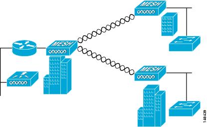
Point-to-Multipoint Wireless Bridging
In the point-to-multipoint bridging scenario, a RAP acting as a root bridge connects multiple MAPs as nonroot bridges with their associated wired LANs. By default, this feature is disabled for all MAPs. If Ethernet bridging is used, you must enable it on the controller for the respective MAP and for the RAP.
Point-to-Point Wireless Bridging
In a point-to-point bridging scenario, a 1500 Series Mesh AP can be used to extend a remote network by using the backhaul radio to bridge two segments of a switched network. This is fundamentally a wireless mesh network with one MAP and no WLAN clients. Just as in point-to-multipoint networks, client access can still be provided with Ethernet bridging enabled, although if bridging between buildings, MAP coverage from a high rooftop might not be suitable for client access.
If you intend to use an Ethernet bridged application, we recommend that you enable the bridging feature on the RAP and on all MAPs in that segment. You must verify that any attached switches to the Ethernet ports of your MAPs are not using VLAN Trunking Protocol (VTP). VTP can reconfigure the trunked VLANs across your mesh and possibly cause a loss in connection for your RAP to its primary WLC. An incorrect configuration can take down your mesh deployment.

For security reasons the Ethernet port on the MAPs is disabled by default. It can be enabled only by configuring Ethernet bridging on the Root and the respective MAPs. To enable Ethernet bridging using the controller GUI, choose page, click the Mesh tab, and then select the Ethernet Bridging check box.
Note | The overall throughput of backhaul radio decreases by half for each hop of a mesh tree. When the Ethernet-bridged clients are used in MAPs and heavy traffic is passed, it may result in a high throughput consumption, which may cause the downlink MAPs to disassociate from the network due to throughput starvation. |
Ethernet bridging has to be enabled for the following two scenarios:
When you want to use the mesh nodes as bridges.
When you want to connect Ethernet devices such as a video camera on the MAP using its Ethernet port.
Ensure that you enable Ethernet bridging for every parent mesh AP taking the path from the mesh AP in question to the controller. For example, if you enable Ethernet bridging on MAP2 in Hop 2, then you must also enable Ethernet bridging on MAP1 (parent MAP), and on the RAP connecting to the controller.
To configure range parameters for longer links, choose . Optimum distance (in feet) should exist between the root access point (RAP) and the farthest mesh access point (MAP). Range from the RAP bridge to the MAP bridge has to be mentioned in feet.
The following global parameter applies to all mesh access points when they join the controller and all existing mesh access points in the network:
- Configuring Mesh Range (CLI)
- Assumptions for the AP1522 Range Calculator
- Assumptions for the AP1552 Range Calculator
Configuring Mesh Range (CLI)
To configure the distance between the nodes doing the bridging, enter the config mesh range command.
APs reboot after you specify the range.
NoteTo estimate the range and the AP density, you can use range calculators that are available at:
Cisco 1520 Series Outdoor Mesh Range Calculation Utility: http://www.cisco.com/en/US/products/ps8368/products_implementation_design_guides_list.html
Range Calculator for 1550 Series Outdoor Mesh Access Points: http://www.cisco.com/en/US/products/ps11451/products_implementation_design_guides_list.html
To view the mesh range, enter the show mesh config command.
Assumptions for the AP1522 Range Calculator
- The AP1522 Range Calculator has been edited to stay within limitations for Tx power and EIRP under the listed regulatory domains. There may be cases where it exceeds the limitations. You must verify that the installation is within the laws of the location in which it is being installed.
- When you use the AP1522 Range Calculator, available power levels change based upon the regulatory domain, the antenna (or antenna gain) selected, the modulation mode, which is based on the data rate selected (OFDM requires a lower power level in some domains). You must verify all parameters after making any parameter changes.
- Rx sensitivity in 2.4 GHz is the composite sensitivity of all three Rx paths. That is, MRC is included in 2.4 GHz. There is only one Rx for 5 GHz.
- You can choose only the channels that the access point is certified for.
- You can select only valid power levels.
Assumptions for the AP1552 Range Calculator
- The AP1552 Range Calculator has been edited to stay within limitations for Tx power and EIRP under the listed regulatory domains. There may be cases where it exceeds the limitations. You must verify that the installation is within the laws of the location in which it is being installed.
- All three antenna ports must be used for external antenna models of 1552 for effective performance. Otherwise, range is significantly compromised. 1552 radios have two Tx paths and three Rx paths.
- The Tx power is the total composite power of both Tx paths.
- Rx sensitivity is the composite sensitivity of all three Rx paths. That is, MRC is included.
- The AP1552 Range Calculator assumes that ClientLink (Beamforming) is switched on.
- You can select a different antenna than the two that are available by default. If you enter a high gain antenna and choose a power that goes over the EIRP limit, then you get a warning and the range equals 0.
- You can choose only the channels that the access point is certified for.
- You can only select only valid power levels.