High Power Counter-Propagating and Co-Propagating Raman units for the Cisco ONS 15454 Multiservice Transport Platform (MSTP)
Available Languages
Product Overview
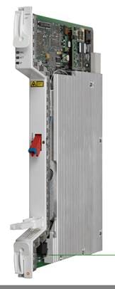
The Cisco® ONS 15454 Multiservice Transport Platform (MSTP) High-Power Counter-Propagating and Co‑Propagating Raman Amplifiers (Figure 1) operate in the C-band region of the optical spectrum to extend the reach and capacity of regional, long-haul, and ultra-long-haul optical networks beyond what is achievable through standard Raman amplifiers or Erbium Doped Fiber Amplifiers (EDFAs). These cards are part of the Cisco ONS 15454 MSTP intelligent dense wavelength division multiplexing (DWDM) platform, engineered to reduce DWDM complexity and speed the deployment of next-generation networking solutions.
Supporting 96 channels in the C band, the Cisco ONS 15454 High-Power Counter- and Co-Propagating Raman Amplifiers (15454-M-RAMAN-CTP and 15454-M-RAMAN-COP, respectively) are plug-in modules that provide the reach and optical performance required to meet the most demanding distance requirements of service provider and enterprise DWDM networks.
(15454-M-RAMAN-CTP and 15454-M-RAMAN-COP)


A Raman amplifier uses the intrinsic properties of silica fiber to obtain signal amplification, such that transmission fibers themselves can be used as a medium for amplification, allowing the attenuation of data signals transmitted over the fiber to be mitigated within the fiber itself. An amplifier working on the basis of this principle is commonly known as a distributed Raman amplifier (DRA) or simply a Raman amplifier. The high-power counter- and co-propagating Raman amplifiers are a marked improvement on this technology. In contrast to the standard Raman amplifier where a single counter-propagating Raman pump signal is responsible for the amplification of the traffic signals in the fiber, there are two units: the high power counter-propagating card, which in itself possesses a superior amplification capability compared to a standard Raman amplifier, and a co-propagating Raman card. Together the two units generate Raman pump signals that co- and counter-propagate with the data signal, amplifying it through the Raman effect. Together, the co- and counter-propagating Raman pumps from these units provide amplification to combat signal attenuation in fiber over a much longer distance than previously possible, considerably extending the reach of a single DWDM span.
As explained in Table 1, two different deployment options are available. One uses the high power counter-propagating unit alone, and the second uses both units, depending on the span length that needs to be traversed.
Table 1. Cisco ONS 15454 MSTP High-Power Counter- and Co-Propagating Raman Amplifier Deployment Configurations
| Feature |
Deployment Application |
| High power counter- and co-propagating Raman amplifiers (15454-M-RAMAN-CTP and 15454-M-RAMAN-COP) together (primary-secondary configuration) |
The high power counter-propagating unit injects counter-propagating optical power to generate a Raman effect in the span fiber and thus amplifies the signals propagating in the same fiber. Similarly, the co-propagating Raman unit injects co-propagating optical power that also amplifies the signal through a Raman effect in fiber. The signal thus receives amplification from the optical power injected by both these units present on opposite ends of the span. |
| High power counter-propagating Raman unit (15454-M-RAMAN-CTP) alone |
The high power counter-propagating unit injects counter-propagating optical power to generate a Raman effect in the span fiber and thus amplifies the signals propagating in the same fiber. |
Product Overview and Applications
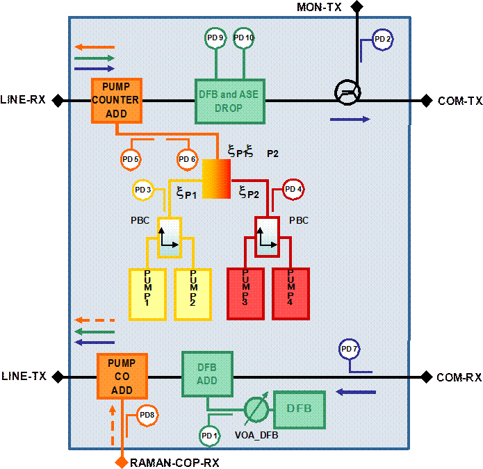
The high power counter- and co-propagating Raman amplifiers take advantage of the latest in amplifier technology, variable optical attenuators, photo diodes, and extensive software to facilitate a high degree of automation for simplified operations. The Raman pumps embedded in the two units use the latest laser technology, delivering up to 1000 mW of optical power by combining just four pump lasers, thus obtaining a very high efficiency and low power consumption while making possible an extended amplification process for long-haul transmission systems. Figures 2 and 3 show the functional block diagrams of both units.


The counter-propagating Raman amplifier includes an embedded distributed-feedback (DFB) laser at 1568.77 nm to be used for optical safety (link continuity). When loss of signal (LOS) is detected (a related fail-low alarm threshold for a period longer than a preset time span), the DFB laser and Raman pumps automatically shut down for optical safety and automatically restart at detection of valid restart conditions. The shutdown and restart functions can be managed through manual commands from hardware or software, providing an enhanced approach to optical safety. The pumps added from the co-propagating Raman unit to the counter-propagating Raman unit and the associated DFB act in a similar fashion. The counter-propagating unit provides parallel, low failure-in-time (FIT) optical safety functions, which allow the classification of the unit as Class 1M as defined by IEC/EN 60825-1. The embedded detection devices and control mechanisms allow the operator to shut down the amplifier (lowering its transmit optical power below the level defined in the recommendation mentioned previously) if any of the following situations occur:
● Raman pump back-reflection, which may be caused by bad connectors or similar problems with the span fiber
● Detection of open connectors
● Detection of broken fiber up to several tens of kilometers from the node
The counter-propagating unit allows full monitoring of pump power, signal power, and DFB laser power; whereas only the pump power can be monitored in the co-propagating unit. Both units feature a Raman pump back-reflection detector.
Due to their potential length, DWDM network spans using Raman amplification may exhibit loss exceeding the reach of the optical supervisory channel (OSC) interface. In these cases, the data-communications-network (DCN) extension capabilities of the Cisco ONS 15454 MSTP can be used to help ensure the correct operation and support of the embedded intelligent optical applications, such as Cisco Wavelength Path Provisioning (WPP), Automatic Power Control (APC), Network Topology Autodiscovery, and Network-Level Alarm Correlation (NLAC). DCN extension can be implemented over an out-of-band network, or the General Communications Channel (GCC) provided by the G.709 overhead present on a provisioned wavelength.
Selection and deployment of the Cisco ONS 15454 counter- and co-propagating Raman units depend on the requirements of the network. The Cisco Transport Planner optical design tool is available to assist in the engineering, design modeling, bill-of-materials (BoM) generation, and deployment of the DWDM network.
Both units incorporate faceplate-mounted LEDs to provide a quick visual check of the operational status of the card. Printed on each of the faceplates is an icon, an orange circle, which is mapped to shelf-slot icons indicating the shelf slot where the card can be physically installed.
Using the counter- and co-propagating amplifiers, the Cisco ONS 15454 MSTP can support numerous applications, including the following.
● Support for very long single spans: The primary application of these high-power Raman amplifiers is to provide distributed amplification in very long single spans. The counter- and co-propagating units can provide high capacity over very long fiber spans where intermediate amplification or regeneration cannot be supported (such as repeaterless submarine links or festoon applications). Up to 155-mile (250-km) single-span systems are possible using 10-Gbps and 40-Gbps wavelengths. Using 100-Gbps wavelengths, the single-span reach of the system can be extended to approximately 130 miles (210 km). The maximum single-span reach attainable by employing Raman amplification with up to 8 channels, using both units, is 61dB.
● Ultra-long-haul unregenerated transmission: The high power counter-propagating units can be used in conjunction with EDFA-based optical amplification to extend the unregenerated reach of DWDM systems by preserving optical signal-to-noise ratio (OSNR) as multiple spans are traversed, allowing for systems up to 2000 miles (3200 km) in length.
● Improved transmission reach and capacity for networks with long spans: Many DWDM networks are deployed in locations where excessively long spans exist because of the geography of the region. EDFA-based systems suffer a high OSNR degradation when the wavelengths cross these long spans because of their high attenuation and tilt. Selective use of Raman amplification can lower the insertion loss of these spans and improve the overall unregenerated distance and system capacity.
● Expansion of system capacity to 96 channels: These Raman amplifiers, in addition to the Enhanced C-Band 96-Channel EDFA Amplifiers, support up to 96 channels in the C band, allowing 50-GHz systems to reach 9.6 Tbps of capacity with 100-Gbps wavelengths.
● Upgrade of transmission systems to higher per-channel bit rates: Increasing the bit rate of the wavelengths in the system typically creates the need to guarantee a higher OSNR for these wavelengths. As systems transition to 100-Gbps (and greater) wavelengths, Raman amplification can be selectively deployed to improve overall system performance and allow the upgrade of existing systems to higher per-wavelength bit rates.
● Reduced latency of storage-area-network (SAN) services: The higher OSNR achieved by selective use of Raman amplifiers in the DWDM network supports the possible avoidance of Forward Error Correction (FEC), reducing end-to-end latency.
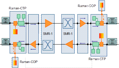
To equalize the Raman gain ripple, the high-power Raman amplifiers must be equipped in nodes with equalization ability: either a dynamic gain-equalizer (DGE) node or a reconfigurable optical add/drop multiplexing (ROADM) node. Multiple options are possible and are detailed in Figures 4 through 6.


Product Specifications
Tables 2 through 6 provide the specifications for the Cisco ONS 15454 High-Power Counter- and Co-Propagating Raman Amplifiers.
Table 2. Regulatory Compliance
| ANSI (SONET) System |
ETSI (SDH) System |
| Countries Supported |
|
|
● Canada
● United States
● Korea
|
● Europe
● Latin America
● Japan
● Asia Pacific
● Middle East and Africa
|
| EMC (Class A) |
|
|
● ICES-003 Issue 4 (2004)
● GR-1089-CORE, Issue 4 (Type 2 and Type 4 equipment)
● GR-1089-CORE – Issue 03 (Oct 2002) (Objective O3-2 – Section 3.2.1 – Radiated Emissions requirements with all doors open)
● FCC 47CFR15, Class A subpart B (2006)
|
● EN 300 386 v1.3.3 (2005) and v1.4.1 (2007)
● CISPR 22 – Fifth edition (2005-04) Class A and the amendment 1 (2005-07)
● CISPR 24 – First edition (1997-09) and amendment 1 (2001-07) and amendment 2 (2002-10).
● EN 55022:1998 Class A – CENELEC Amendment A2:2003
● EN 55024:1998 – CENELEC Amendment A1:2001 and Amendment A2:2003
● Resolution 237 (Brazil)
● VCCI V-3/2006.04
● EN 61000-6-1:2001
● EN 61000-6-2:1999
|
| Safety |
|
|
● UL/CSA 60950 -1 First Edition (2003)
● GR-1089-CORE, Issue 4 (Type 2 and Type 4 equipment)
|
● UL/CSA 60950 -1 First Edition (2003)
● IEC 60950-1 (2001/10)/Amendment 11:2004 to EN 60950-1:2001, 1st Edition (with all country deviations)
|
| Environmental |
|
|
● GR-63-CORE, Issue 3 (2006)
|
● ETS 300-019-2-1 V2.1.2 (Storage, Class 1.1)
● ETS 300-019-2-2 V2.1.2 (Transportation, Class 2.3)
● ETS 300-019-2-3 V2.1.2 (Operational, Class 3.1E)
● EU WEEE regulation
● EU RoHS regulation
|
| Optical Safety |
|
|
● EN or IEC-60825-2 Third edition (2004-06)
● EN or IEC 60825-1 Consol. Ed. 1.2 – incl. am1+am2 (2001-08)
● 21CFR1040 (2004/04) (Accession Letter and CDRH Report)
● IEC-60825-2 Third edition (2004-06)
● ITU-T G.664 (2006)
|
|
| Miscellaneous |
|
|
● Acoustic noise
◦ GR-63-CORE, Issue 3 (2006)
◦ ETS 300 753 ed.1 (1997-10)
● Rain, sand, dust, and moisture proofing
◦ AS 1939-1990, 4.2, IP 53
● Mechanical shock and bumps
◦ AS1099- 2.27
● Customer-specific requirements
◦ AT&T Network Equipment Development Standards (NEDS) Generic Requirements, AT&T 802-900-260
◦ SBC TP76200MP
◦ Verizon SIT.NEBS.NPI.2002.010
|
|
Table 3. System Requirements
| Component |
Cisco ONS 15454 M6 |
Cisco ONS 15454 M2 |
| Processor |
TNC/TSC/TNC-E/TSC-E |
TNC/TSC/TNC-E/TSC-E |
| Shelf assembly |
15454-M6-SA shelf assembly with FTA2 |
15454-M2-SA shelf assembly with FTA2 |
| System software |
Release 9.3 ANSI/ETSI or later |
Release 9.3 ANSI/ETSI or later |
| Slot compatibility |
Slots 2 through 7 |
Slots 2 through 3 |
Table 4. Card Specifications
| Specification |
Value |
| Management |
|
| Card LEDs
● Failure (FAIL)
● Active/standby (ACT/STBY)
● Signal fail (SF)
|
Red Green /yellow Yellow |
| General Specifications |
|
| General power drawn
● Typical
● Maximum
|
80W 90W |
| Weight (not including clamshell) |
3.17 lb (1.44 kg) |
| Optical connectors |
Cisco ONS 15454 High-Power Counter-Propagating Raman Unit (15454-M-RAMAN-CTP)
● Two LC-LC 2m cables to connect to or from COM Rx or COM Tx
● Two ES 2000 PS PC - LC 2m cables to connect to or from LINE Rx or LINE Tx
Cisco ONS 15454 High-Power Co-Propagating Raman Unit (15454-M-RAMAN-COP)
● One ES 2000 PS PC 2m cable to connect to counter-propagating unit (15454-M-RAMAN-CTP)
|
| Size |
One slot |
| Reliability |
|
| Predicted mean time between failure (MTBF) |
15454-M-RAMAN-CTP: 182,263 hrs 15454-M-RAMAN-COP: 110,854 hrs |
| Operating Environment |
|
| Continuous-operation air temperature |
32 to 140°F (0 to 60°C) |
| Short-term operation air temperature per 96 hours per year |
23 to 158°F (–5 to 70°C) |
| Humidity |
5 to 95% noncondensing |
| Storage Environment |
|
| Temperature |
–40 to 158°F (–40 to 70°C) |
| Humidity |
5 to 95% noncondensing |
| Transport Environment |
|
| Temperature |
–40 to 158°F (–40 to 70°C) |
| Humidity |
5 to 95% noncondensing |
Table 5. Optical Amplifier Specifications
| Specification |
Counter-Propagating Unit |
Co-Propagating Unit |
| Pump wavelength |
1428 nm (pumps 1 and 2) 1457 nm (pumps 3 and 4) |
1428 nm (pumps 1 and 2) 1457 nm (pumps 3 and 4) |
| Raman pump unit class |
1 M |
1 M |
| Operating range Raman pump power |
100 to 1000 mW |
200 to 1000 mW |
| Maximum output power: pump laser 1+ 2 (1428 nm) |
500 mW |
550 mW |
| Maximum output power: pump laser 1+ 2 (1457 nm) |
500 mW |
500 mW |
| Pump-power set resolution |
0.1 mW (maximum) |
0.1 mW (maximum) |
| Pump-power precision |
+ or – 2% |
+ or – 2% |
| Optical power-settling time |
0.1 to 1 sec |
0.1 to 1 sec |
| Maximum optical output power – LINE Rx port |
1200 mW (maximum) |
1200 mW (maximum) |
| C-band signal wavelength range |
1500 to 1567 nm (96 channels) |
C-band wavelengths do not propagate through this card. |
| C-band ripple COM-RX to LINE-TX LINE-RX to COM-TX |
0.5 dB (maximum) |
– |
| Insertion loss
●
LINE-RX to COM-TX (1500 to 1527 nm)
●
LINE-RX to COM-TX (1527 to 1567 nm)
●
COM-RX to LINE-TX (1500 to 1527 nm)
●
COM-RX to LINE-TX (1527 to 1567 nm)
● RAMAN-COP-RX to
LINE-TX
● LINE-RX to MON-TX
|
1.75 dB 1.5 dB 1.75 dB 1.5 dB 0.6 dB (pump wavelength) 22– 26 dB (C-band signals) |
– |
| Optical connectors back reflection |
–40 dB (maximum) |
– |
| PDL
●
COM-RX to LINE-TX
●
LINE-RX to COM-TX
|
0.2 dB (maximum) 0.2 dB (maximum) |
– |
| PMD
●
COM-RX to LINE-TX
●
LINE-RX to COM-TX
|
0.15 ps (maximum) 0.15 ps (maximum) |
– |
| C-band ripple
●
COM-RX to LINE-TX
●
LINE-RX to COM-TX
|
0.5 dB (maximum) 0.5 dB (maximum) |
– |
Table 6. DFB Laser Specifications
| Specification |
Value |
| DFB wavelength |
1568.77 nm |
| Operating-range DFB power |
–15 to 6 dBm |
| Off-state DFB laser power |
–50 dBm |
| DFB laser-set resolution |
0.1 mW (maximum) |
| Optical power-settling time |
0.1 to 1 sec |
| Maximum DFB laser power |
10 mW (maximum) |
| DFB spectral width (–3 dB full bandwidth) |
5 MHz (typical) |
| Brillouin suppression (on dispersion shifted fiber) |
12 dBm |
| DFB section class |
1 |
Warranty Information
Warranty information is available on Cisco.com at the Product Warranties page.
Ordering Information
To place an order, visit the Cisco Ordering Home Page and refer to Table 7. To download software, visit the Cisco Software Center.
Table 7. Ordering Information
| Part Number |
Description |
| 15454-M-RAMAN-CTP |
High-Power Counter-Propagating, 1W optical pump output power, C-band, 96-channel 50-GHz Raman unit with 2 ES 2000 PS PC – LC 2m cables |
| 15454-M-RAMAN-COP |
High-Power Co-Propagating, 1W optical pump output power, C-band, 96-channel 50-GHz Raman unit with 1 ES 2000 PS PC 2m cable |
 Feedback