CAB-530 MT Serial Cable Specifications
Available Languages
Contents
Introduction
This document provides the technical and cable specifications for the CAB-530MT serial cable.
Prerequisites
Requirements
There are no specific requirements for this document.
Components Used
This document is not restricted to specific software and hardware versions.
The information in this document was created from the devices in a specific lab environment. All of the devices used in this document started with a cleared (default) configuration. If your network is live, make sure that you understand the potential impact of any command.
Conventions
Refer to Cisco Technical Tips Conventions for more information on document conventions.
CAB-530MT Serial Cable Assembly
The cable gender for this product (part number 72-0797-01) is Male DB-60 to Male DB-25, mode - DTE only.
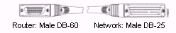
The CAB-530MT cable is used in the Cisco 7000 family, Cisco 4000 series, Cisco 3600 series, Cisco 2500 series, Cisco 1600 series, Cisco access servers, and AccessPro PC cards. This cable has a male DB-60 connector on the Cisco end and a male DB-25 connector on the network end.
EIA-530 DTE Cable Pinouts (DB-60 to DB-25)
The table below shows the EIA-530 DTE cable pinouts (DB-60 to DB-25).
Note: The arrows indicate signal direction:
-
---> indicates DTE to DCE
-
<--- indicates DCE to DTE
| 60 Pin1 | Signal | 25 Pin | Signal | Direction DTE DCE2 |
|---|---|---|---|---|
| J1-11 J1-12 | TxD/RxD+ TxD/RxD- | J2-2 J2-14 | BA(A), TxD+ BA(B), TxD- | ---> ---> |
| J1-28 J1-27 | RxD/TxD+ RxD/TxD- | J2-3 J2-16 | BA(A), RxD+ BB(B), RxD- | <--- <--- |
| J1-9 J1-10 | RTS/CTS+ RTS/CTS- | J2-4 J2-19 | CA(A), RTS+ CA(B), RTS- | ---> ---> |
| J1-1 J1-2 | CTS/RTS+ CTS/RTS- | J2-5 J2-13 | CB(A), CTS+ CB(B), CTS- | <--- <--- |
| J1-3 J1-4 | DSR/DTR+ DSR/DTR- | J2-6 J2-22 | CC(A), DSR+ CC(B), DSR- | <--- <--- |
| J1-46 J1-47 | Shield_GND MODE_2 | J2-1 - | Shield - | Shorted |
| J1-48 J1-49 | GND MODE_1 | - - | - - | Shorted |
| J1-5 J1-6 | DCD/DCD+ DCD/DCD- | J2-8 J2-10 | CF(A), DCD+ CF(B), DCD- | <--- <--- |
| J1-24 J1-23 | TxC/RxC+ TxC/RxC- | J2-15 J2-12 | DB(A), TxC+ DB(B), TxC- | <--- <--- |
| J1-26 J1-25 | RxC/TxCE+ RxC/TxCE- | J2-17 J2-9 | DD(A), RxC+ DD(B), RxC- | <--- <--- |
| J1-44 J1-45 | LL/DCD Circuit_GND | J2-18 J2-7 | LL Circuit_ GND | ---> - |
| J1-7 J1-8 | DTR/DSR+ DTR/DSR- | J2-20 J2-23 | CD(A), DTR+ CD(B), DTR- | ---> ---> |
| J1-13 J1-14 | TxCE/TxC+ TxCE/TxC- | J2-24 J2-11 | DA(A), TxCE+ DA(B), TxCE- | ---> ---> |
1Any pin not referenced is not connected.
2The EIA-530 interface cannot be operated in DCE mode. A DCE cable is not available for the EIA-530 interface.
Related Information
Revision History
| Revision | Publish Date | Comments |
|---|---|---|
1.0 |
19-Nov-2003
|
Initial Release |
 Feedback
Contact Cisco
- Open a Support Case

- (Requires a Cisco Service Contract)