5-in-1 V.35 Assembly and Pinouts
Available Languages
Contents
Introduction
This document explains the V.35 serial cable assembly and pinouts.
Prerequisites
Requirements
There are no specific requirements for this document.
Components Used
This document is not restricted to specific software and hardware versions.
The information in this document was created from the devices in a specific lab environment. All of the devices used in this document started with a cleared (default) configuration. If your network is live, make sure that you understand the potential impact of any command.
Conventions
For more information on document conventions, refer to the Cisco Technical Tips Conventions.
V.35 Speed and Distance Limitations
The table here lists the different V.35 speed and distance limitations:
 Caution: The EIA,TIA-449 and V.35 interfaces support data rates up to 2.048 Mbps. Cisco advices not to exceed this maximum as it could result in loss of data.
| Data Rate (Baud) | Distance (Feet) | Distance (Meters) |
|---|---|---|
| 2400 | 4,100 | 1,250 |
| 4800 | 2,050 | 625 |
| 9600 | 1,025 | 312 |
| 19200 | 513 | 156 |
| 38400 | 256 | 78 |
| 56000 | 102 | 31 |
| T1 | 50 | 15 |
CAB-V35MT Serial Cable Assembly
The cable gender for this product (part number 72-0791-01) is male DB-60 to male Winchester 15 Pin, mode - DTE.
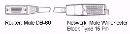
The CAB-V35MT serial cable is used in the Cisco 7000 family, Cisco 4000 series, Cisco 3600 series, Cisco 2500 series, Cisco 1600 series, Cisco access servers, and AccessPro PC cards. This cable has a male DB-60 connector on the Cisco end and a male Winchester connector on the network end.
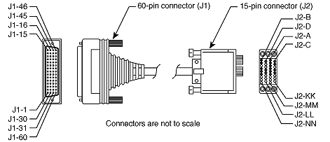
V.35 DTE Cable Pinouts (DB-60 to 34-Pin)
The table here shows the V.35 DTE cable pinouts (DB-60 to 34-Pin).
Note: The arrows indicate signal direction:
-
---> indicates DTE to DCE
-
<--- indicates DCE to DTE
| 60 Pin1 | Signal | Description | Direction | 34 Pin | Signal |
|---|---|---|---|---|---|
| J1-49 J1-48 | MODE_1 GND | Shorting Group | -- | -- | -- |
| J1-50 J1-51 J1-52 | MODE_0 GND MODE_DCE | Shorting Group | -- | -- | -- |
| J1-53 J1-54 J1-55 J1-56 | TxC/NIL RxC_TxCE RxD/TxD GND | Shorting Group | -- | -- | -- |
| J1-46 | Shield_GND | Single | -- | J2-A | Frame GND |
| J1-45 Shield | Circuit_GND -- | Twisted pair no. 12 | -- -- | J2-B Shield | Circuit_GND -- |
| J1-42 Shield | RTS/CTS -- | Twisted pair no. 9 | --> -- | J2-C Shield | RTS -- |
| J1-35 Shield | CTS/RTS -- | Twisted pair no. 8 | <-- -- | J2-D Shield | CTS -- |
| J1-34 Shield | DSR/DTR -- | Twisted pair no. 7 | <-- -- | J2-E Shield | DSR -- |
| J1-33 Shield | DCD/LL -- | Twisted pair no.6 | <-- -- | J2-F Shield | RLSD -- |
| J1-43 Shield | DTR/DSR -- | Twisted pair no. 10 | --> -- | J2-H Shield | DTR -- |
| J1-44 Shield | LL/DCD -- | Twisted pair no. 11 | --> -- | J2-K Shield | LT -- |
| J1-18 J1-17 | TxD/RxD+ TxD/RxD-- | Twisted pair no. 1 | --> --> | J2-P J2-S | SD+ SD-- |
| J1-28 J1-27 | RxD/TxD+ RxD/TxD-- | Twisted pair no. 5 | <-- <-- | J2-R J2-T | RD+ RD-- |
| J1-20 J1-19 | TxCE/TxC+ TxCE/TxC-- | Twisted pair no. 2 | --> --> | J2-U J2-W | SCTE+ SCTE-- |
| J1-26 J1-25 | RxC/TxCE+ RxC/TxCE-- | Twisted pair no. 4 | <-- <-- | J2-V J2-X | SCR+ SCR-- |
| J1-24 J1-23 | TxC/RxC+ TxC/RxC-- | Twisted pair no. 3 | <-- <-- | J2-Y J2-AA | SCT+ SCT-- |
1Any pin not referenced is not connected.
CAB-V35FC Serial Cable Assembly
The cable gender for this product (part number 72-0792-01) is male DB-60 to female Winchester Block Type, mode - DCE.
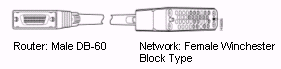
The CAB-V35FC serial cable is used in the Cisco 7000 family, Cisco 4000 series, Cisco 3600 series, Cisco 2500 series, Cisco 1600 series, Cisco access servers, and AccessPro PC cards. This cable has a male DB-60 connector on the Cisco end and a female Winchester connector on the network end.
V.35 DCE Cable Pinouts (DB-60 to 34-Pin)
The table here shows the V.35 DCE cable pinouts (DB-60 to 34-Pin).
Note: The arrows indicate signal direction:
-
---> indicates DTE to DCE
-
<--- indicates DCE to DTE
| 60 Pin1 | Signal | Description | Direction | 34 Pin | Signal |
|---|---|---|---|---|---|
| J1-49 J1-48 | MODE_1 GND | Shorting Group | -- | -- | -- |
| J1-50 J1-51 | MODE_0 GND | Shorting Group | -- | -- | -- |
| J1-53 J1-54 J1-55 J1-56 | TxC/NIL RxC_TxCE RxD/TxD GND | Shorting Group | -- | -- | -- |
| J1-46 | Shield_GND | Single | -- | J2-A | Frame GND |
| J1-45 Shield | Circuit_GND -- | Twisted pair no. 12 | -- -- | J2-B Shield | Circuit_GND -- |
| J1-35 Shield | CTS/RTS -- | Twisted pair no. 8 | <-- -- | J2-C Shield | RTS -- |
| J1-42 Shield | RTS/CTS -- | Twisted pair no. 9 | --> -- | J2-D Shield | CTS -- |
| J1-43 Shield | DTR/DSR -- | Twisted pair no. 10 | --> -- | J2-E Shield | DSR -- |
| J1-44 Shield | LL/DCD -- | Twisted pair no. 11 | --> -- | J2-F Shield | RLSD -- |
| J1-34 Shield | DSR/DTR -- | Twisted pair no.7 | <-- -- | J2-H Shield | DTR -- |
| J1-33 Shield | DCD/LL -- | Twisted pair no. 6 | <-- -- | J2-K Shield | LT -- |
| J1-28 J1-27 | RxD/TxD+ RxD/TxD-- | Twisted pair no. 5 | <-- <-- | J2-P J2-S | SD+ SD-- |
| J1-18 J1-17 | TxD/RxD+ TxD/RxD-- | Twisted pair no. 1 | --> --> | J2-R J2-T | RD+ RD-- |
| J1-26 J1-25 | RxC/TxCE+ RxC/TxCE-- | Twisted pair no. 4 | <-- <-- | J2-U J2-W | SCTE+ SCTE-- |
| J1-22 J1-21 | NIL/RxC+ NIL/RxC-- | Twisted pair no. 3 | --> --> | J2-V J2-X | SCR+ SCR-- |
| J1-20 J1-19 | TxCE/TxC+ TxCE/TxC-- | Twisted pair no. 2 | --> --> | J2-Y J2-AA | SCT+ SCT-- |
1Any pin that is not referenced is not connected.
Related Information
Revision History
| Revision | Publish Date | Comments |
|---|---|---|
1.0 |
19-Nov-2003
|
Initial Release |
 Feedback
Contact Cisco
- Open a Support Case

- (Requires a Cisco Service Contract)