Introduction
This document describes the cable and connector requirements for console and auxiliary (AUX) ports.
Prerequisites
Requirements
There are no specific requirements for this document.
Components Used
This document is not restricted to specific software and hardware versions.
The information in this document was created from the devices in a specific lab environment. All of the devices used in this document started with a cleared (default) configuration. If your network is live, ensure that you understand the potential impact of any command.
Conventions
Refer to Cisco Technical Tips Conventions for more information on document conventions.
Background Information
Cisco routers either have RJ-45-based or DB-25 DCE/DTE console and AUX ports. You can connect either a terminal (DTE) or a modem (DCE) to these ports. In either instance, you need both an RJ-45 cable and an RJ-45-to-DB-25 or RJ-45-to-DB-9 connector.
Console Port Settings for Terminal Connection
Before you connect a terminal to the console port, configure the terminal to match the router console port as shown here:
-
9600 baud
-
8 data bits
-
No parity
- 2 stop bits (9600 8N2) OR 1 stop bit
Types of Console and AUX Connectors
Cisco routers have three types of console and AUX connectors. The table in this section lists these types:
-
RJ-45
-
DB-25 DCE
-
DB-25 DTE
There are three styles of RJ-45-to-DB-25 connectors:
-
DCE style (modem)
-
DTE style
-
DCE style (non-modem)
Each of these styles has a different role. Generally, DTE is for terminals, DCE (modem) is for modems, and DCE (non-modem) is obsolete.
Note: Move pin 6 to pin 8 if you want to change a DCE style (non-modem) to a DCE style (modem).
Console and AUX Connectors for Cisco Routers
| Connector |
Graphic |
| RJ-45 |
 RJ-45 RJ-45
|
| DB-25 DCE |
 DB-25 DCE DB-25 DCE
|
| DB-25 DTE |
 DB-25 DTE DB-25 DTE
|
Cable for console and AUX port:
RJ-45 Cables
Cisco products use these types of RJ-45 cables:
Cisco does not provide these cables. These cables are widely available from other sources. Console cable is usually provided with the Console Cable Kit.
Note: The console port does not support modem control or hardware flow control.
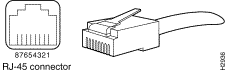
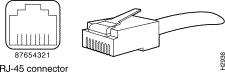 RJ-45 Connector
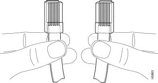
How to Identify an RJ-45 Cable
In order to identify the RJ-45 cable type, hold the two ends of the cable next to one another so you can see the colored wires inside the ends, as shown here:
 RJ-45 Cable Ends
There are three types of commonly used RJ-45 cables: straight, cross and rolled. Hold the two ends of an RJ-45 cable side by side. There are eight colored strips, or pins, at each end. If the order of the colored pins is the same at each end, the cable is straight. If the order of the colors is reversed at each end, the cable is rolled.
Examine the sequence of colored wires to determine the type of RJ-45 cable. This section explains how you can do this.
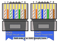
Straight-through Cable
In a straight-through cable, the colored wires are in the same sequence at both ends of the cable.
Straight-through Cable
 Straight-through Cable
RJ-45 Straight-through (Ethernet) Cable Pin-outs
| Signal |
RJ-45 Pin |
RJ-45 Pin |
Signal |
| Tx+ |
1 |
1 |
Tx+ |
| Tx– |
2 |
2 |
Tx– |
| Rx+ |
3 |
3 |
Rx+ |
| – |
4 |
4 |
– |
| – |
5 |
5 |
– |
| Rx– |
6 |
6 |
Rx– |
| – |
7 |
7 |
– |
| – |
8 |
8 |
– |
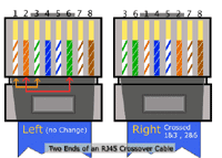
Crossover Cable
In a crossover cable, the first (far left) colored wire at one end of the cable is the third colored wire at the other end of the cable.
Crossover Cable
 Crossover Cable
RJ-45 Crossover (Ethernet) Cable Pin-outs
| Signal |
RJ-45 Pin |
RJ-45 Pin |
Signal |
| Tx+ |
1 |
3 |
Rx+ |
| Tx– |
2 |
6 |
Rx– |
| Rx+ |
3 |
1 |
Tx+ |
| – |
4 |
4 |
– |
| – |
5 |
5 |
– |
| Rx– |
6 |
2 |
Tx– |
| – |
7 |
7 |
– |
| – |
8 |
8 |
– |
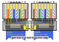
Rolled Cable
In a rolled cable, the colored wires at one end of the cable are in the reverse sequence of the colored wires at the other end of the cable.
Rolled Cable
 Rolled Cable
Rolled Cable Pin-outs
| Signal |
RJ-45 Pin |
RJ-45 Pin |
Signal |
| – |
1 |
8 |
– |
| – |
2 |
7 |
– |
| – |
3 |
6 |
– |
| – |
4 |
5 |
– |
| – |
5 |
4 |
– |
| – |
6 |
3 |
– |
| – |
7 |
2 |
– |
| – |
8 |
1 |
– |
Note: CAB-OCTAL-ASYNC, the 8-port RJ-45 adapter that is used with the Cisco 2509, 2510, 2511, and 2512, is the same as a rolled cable.
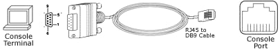
RJ-45 to DB-9 Female*
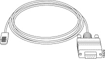 RJ-45 to DB-9 Female*
This cable is also known as Management Cable.
- Cisco provides this cable with the 600, 800, 1600 and 1700 Series Routers.
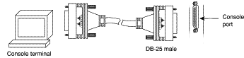
Type of Cable for DB-25 Connectors
RS 232 Straight-through Cable
This illustration shows serial cable CAB-R23= (part number 74-0173), which is a general serial cable for all router platforms:
Both Ends of RS 232 Straight-through Cable for DB-25 Connectors
 Both Ends of RS 232 Straight-through Cable for DB-25 Connectors
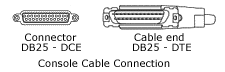
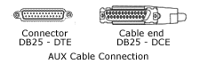
This cable has a female DB-25 connector on one end and a male DB-25 connector on the other end. Either end of the CAB-R23 cable can be the Cisco end or the network end, based on whether the Cisco router is designated as a DCE device or a DTE device. If the router is designated as a DCE device, the female DB-25 connector is the Cisco end. If the router is designated as a DTE device, the male DB-25 connector is the Cisco end.
Pin-outs for RS 232 Straight Through Cable (DB-25)
| Male DTE Pin-outs |
Female DTE Pin-outs |
| 25 Pin |
Signal |
25 Pin |
Signal |
| – |
– |
|
|
| J2-1 |
Shield GND |
J2-1 |
Shield GND |
| J2-2 Shield |
TxD – |
J2-2 Shield |
TxD – |
| J2-3 Shield |
RxD – |
J2-3 Shield |
RxD – |
| J2-4 Shield |
RTS – |
J2-4 Shield |
RTS – |
| J2-5 Shield |
CTS – |
J2-5 Shield |
CTS – |
| J2-6 Shield |
DSR – |
J2-6 Shield |
DSR – |
| J2-7 Shield |
Circuit GND – |
J2-7 Shield |
Circuit GND |
| J2-8 Shield |
DCD – |
J2-8 Shield |
DCD – |
| J2-15 Shield |
TxC – |
J2-15 Shield |
TxC – |
| J2-17 Shield |
RxC – |
J2-17 Shield |
RxC – |
| J2-18 Shield |
LTST – |
J2-18 Shield |
LTST – |
| J2-20 Shield |
DTR – |
J2-20 Shield |
DTR – |
| J2-24 Shield |
TxCE – |
J2-24 Shield |
TxCE – |
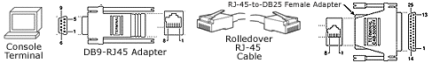
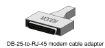
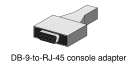
Adapters
You need two types of adapters to connect a PC to a router.
-
RJ-45-to-DB-9 Adapter
-
RJ-45-to-DB-25 Adapter
RJ-45-to-DB-9 Adapter
This adapter connects a router to a PC though a COM port.
RJ-45-to-DB-9 Adapter
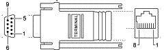 RJ-45-to-DB-9 Adapter
RJ-45-to-DB-25 Adapter
This adapter connects a router to PC through a serial port.
RJ-45-to-DB-25 Adapter
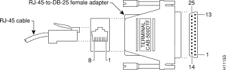 RJ-45-to-DB-25 Adapter-Female Adapter
Cable and Adapter Setups that Work
Here are the most common ways to console into a router.
Console Connection Combination
| Console Port |
Cable |
Adapter for PC |
Adapter for Console Port |
| RJ-45 |
RJ-45 Rolled |
DB-9 / DB-25 |
None |
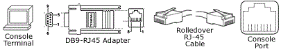 DB9-RJRT Adapter-Rolled Over RJ-45 Cable DB9-RJRT Adapter-Rolled Over RJ-45 Cable
|
| DB-25 DCE |
RJ-45 Rolled |
DB-9 / DB-25 |
RJ-45-to-DB-25 |
|
| DB-25 DCE |
DB-25 |
None |
None |
 DB-25 DCE, DB-25, None, None DB-25 DCE, DB-25, None, None
|
| RJ-45 |
RJ-45-to-DB-9 |
None |
None |
|
- Cisco provides this cable with the Cisco 600, 800, 1600 and 1700 Series Routers.
You cannot mix and match these components randomly. Here are the combinations that work:
Console Connection Combination
| Port |
RJ-45 Cable |
DB-25 Adapter |
To Attach |
| AUX / Console |
Straight |
DCE non-modem |
TERMINAL |
| AUX / Console |
Rolled |
DTE |
TERMINAL |
| AUX / Console |
Rolled |
DCE modem |
MODEM |
| AUX / Console |
RJ-45-to-DB9 |
None |
TERMINAL |
These are the only setups that work. If you do not have the components you need, use the RJ-45 Component Guide chart to order them.
RJ-45 Port and Adapter Pin-outs
This chart shows the pin-outs for RJ-45 console and AUX ports. The console port does not use RTS/CTS.
RJ-45 Port Pin-outs
| Signal |
Console Port (DTE) |
RJ-45 Rolled Cable |
Adapter |
Adapter |
Signal |
|
RJ-45 |
RJ-45 Pin |
DB-9 Pin |
DB-25 Pin |
|
| CTS |
1 |
8 |
7 |
4 |
RTS |
| DTR |
2 |
7 |
4 |
20 |
DSR |
| TxD |
3 |
6 |
3 |
2 |
RxD |
| GND |
4 |
5 |
5 |
7 |
GND |
| GND |
5 |
4 |
5 |
7 |
GND |
| RxD |
6 |
3 |
2 |
3 |
TxD |
| DSR |
7 |
2 |
6 |
8 |
DTR |
| RTS |
8 |
1 |
8 |
5 |
CTS |
DB-25 Console and AUX Port Pin-outs
Console Port Signals
| Pin |
Signal |
Direction |
Description |
| 1 |
GND |
– |
Ground |
| 2 |
TxD |
<-- |
Transmit Data |
| 3 |
RxD |
--> |
Receive Data |
| 6 |
DSR |
--> |
Data Set Ready (always on) |
| 7 |
GND |
– |
Ground |
| 8 |
DCD |
--> |
Data Carrier Detect (always on) |
Note: The console port does not support modem control or hardware flow control.
Auxiliary Port Signals
| Pin |
Signal |
Direction |
Description |
| 2 |
TxD |
--> |
Transmit Data |
| 3 |
RxD |
<-- |
Receive Data |
| 4 |
RTS |
--> |
Request To Send (used for hardware control) |
| 5 |
CTS |
<-- |
Clear To Send (used for hardware flow control) |
| 6 |
DSR |
<-- |
Data Set Ready |
| 7 |
Signal Ground |
– |
Carrier Detect (used for modem control) |
| 8 |
CD |
<-- |
Data Terminal Ready (used for modem control only) |
| 20 |
DTR |
--> |
|
Note: The auxiliary port supports hardware flow control and modem control.
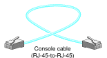
Console Cable Kit
A console cable kit is provided with your router. Use this kit when you connect your router to a PC or a terminal.
The console cable kit contains these items:
-
RJ-45-to-RJ-45 console cable (blue)
-
RJ-45-to-DB-25 adapter (gray)
-
RJ-45-to-DB-9 adapter (gray)
Note: The Cisco 7200 Series and Cisco 7301 are not shipped by default with a console cable kit. If a console cable is required, order an accessory kit (part number: ACS-2500ASYN).
| RJ-45-to-RJ-45 console cable |
RJ-45-to-DB-25 adapter |
RJ-45-to-DB-9 adapter |
 RJ-45-to-RJ-45 Console Cable RJ-45-to-RJ-45 Console Cable
|
 RJ-45-to-DB-25 Adapter RJ-45-to-DB-25 Adapter
|
 DB-9-to-RJ-45 Console Adapter DB-9-to-RJ-45 Console Adapter
|
Cisco RJ-45 Component Guide
This chart summarizes the RJ-45 components of Cisco:
RJ-45 Component Guide
| Style |
Catalog Part Number |
Catalog Description |
Label |
Shielded? |
| DTE |
CAB-500DTF= |
DB-25 CONNECTOR, DTE FEMALE |
29-0810-01/29-DTF-01 |
no |
| DTE |
CAB-500DTM= |
DB-25 CONNECTOR, DTE MALE |
|
no |
| modem |
CAB-25AS-MMOD= |
CABLE CONN-MODEM TO RJ45 SHLD |
|
yes |
| modem |
CAB-MMOD= |
ADP,RJ45/DSUB |
29-0881-01/29-MMOD-01 |
no |
| DCE |
CAB-500DCF= |
DB-25 CONNECTOR, (non-modem) DCE FEMALE |
29-0809-01/29-DCF-01 |
no |
| DCE |
CAB-500DCM= |
DB-25 CONNECTOR,(non-modem) DCE MALE |
29-0808-01/29-DCM-0129- 0808-01/29-DCM-01 |
no |
| NA |
Rolled Cable |
CABASY,RJ45 ROLLED, MODULAR |
72-0876-01/CAB-500RJ |
NA |
| NA |
Straight Cable |
–not in catalog– |
31-0756-01 |
NA |
| Cable for DB-25/DB-9 Connection |
| NA |
Depends on the router* |
RJ-45 to DB-9 female an all in one cable |
72-3383-01 |
NA |
| NA |
CAB-R23= |
RS 232 Straight-through Cable |
– |
NA |
| NA |
Depends on the router* |
DB-9 Male to DB-25 male for Modem connection |
29-4043-01 |
NA |
The first seven entries are DB-25 connectors, and the last two are RJ-45 cables. Connectors are described in terms of their sex and their role. For example, an FDTE is a female DTE style connector, an MMOD is a male modem style connector, and so on. Again, you need shielded cables in order to run at 115.2 kbps.
Related Information
 Feedback