PGW 2200 Softswitch PRI Backhaul Resolution
Available Languages
Bias-Free Language
The documentation set for this product strives to use bias-free language. For the purposes of this documentation set, bias-free is defined as language that does not imply discrimination based on age, disability, gender, racial identity, ethnic identity, sexual orientation, socioeconomic status, and intersectionality. Exceptions may be present in the documentation due to language that is hardcoded in the user interfaces of the product software, language used based on RFP documentation, or language that is used by a referenced third-party product. Learn more about how Cisco is using Inclusive Language.
Contents
Introduction
This document helps you troubleshoot information for the PRI backhaul on the Cisco PGW 2200 in Call Control mode. Due to differences between the protocol families, backhauling is divided into several categories. For example, ISDN for Q Signaling (QSIG) and Digital Private Network Signaling System (DPNSS).
This document only covers the PRI backhaul with the Cisco PGW 2200.
Prerequisites
Requirements
Readers of this document should have knowledge of these topics:
Components Used
The information in this document is based on Cisco PGW 2200 Software Releases 9.3(2) and later.
The information in this document was created from the devices in a specific lab environment. All of the devices used in this document started with a cleared (default) configuration. If your network is live, make sure that you understand the potential impact of any command.
Conventions
Refer to Cisco Technical Tips Conventions for more information on document conventions.
PRI Backhaul Resolution Description
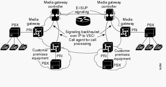
PRI/Q.931 signaling backhaul is the ability to reliably transport the signaling (Q.931 and above layers) from a PRI trunk (see Figure 1). This PRI trunk is physically connected to a media gateway that connects to a media gateway controller (MGC - Cisco PGW 2200) for processing. Signaling backhaul for ISDN PRI occurs at the Layer 2 (Q.921) and Layer 3 (Q.931) boundary. The lower layers of the protocol are terminated and processed on the media gateway (AS5xx0), while the upper layers are backhauled to the Cisco PGW 2200.
The upper layers of the protocol are backhauled, or transported to the Cisco PGW 2200 with the use of Reliable User Datagram Protocol (RUDP) over IP. RUDP provides autonomous notification of connected and failed sessions, and in-sequence, guaranteed delivery of signaling protocols across an IP network. Backhaul Session Manager is a software function on the Cisco PGW 2200 and media gateway that manages RUDP sessions. Signaling backhaul provides the additional advantage of distributed protocol processing. This permits greater expandability and scalability. It also offloads lower layer protocol processing from the Cisco PGW 2200. From the layer model, PRI backhaul is built up into IP/UDP/RUDP/Backhaul-Session-Manager/PRI ISDN Layer 3.
Figure 1: PRI Backhaul


Troubleshoot
Complete these steps in order to troubleshoot PRI Backhaul.
-
Step 3: Check the Session Manager link between the Cisco AS5xx0 and the Cisco PGW 2200.
-
Step 4: Check the Q.921 status between the AS5400 and the PABX.
Step 1: Check the Cisco Gateway AS5xx0 Configuration
Complete these steps in order to check the gateway configuration.
-
Issue these commands under global configuration mode to setup the backhauling session manager to talk to the Cisco PGW 2200 if you receive the IOS® error message % BSM: Session is not created, max limit exceeded You can support maximum of 16 session in IOS gateway 5xx0.
backhaul-session-manager
set set1
group group1 set set1
session group group1 x.x.x.x x.x.x.x port priority
This command output shows an example:
backhaul-session-manager
  set pgw-cag client nft
  group pgw-cag set pgw-cag
  session group pgw-cag 213.254.253.140 6000 213.254.252.5 6000 1
  session group pgw-cag 213.254.253.141 6000 213.254.252.5 6000 2
  session group pgw-cag 213.254.253.156 6000 213.254.252.21 6000 3
  session group pgw-cag 213.254.253.157 6000 213.254.252.21 6000 4
Note: The Cisco IOS configuration does not support when you use the Backhaul Session Manager configuration in order to place sessions that point to different physical PGW 2200s under the same group. You need to separate the two PGW 2200s into two groups. Refer to Cisco bug ID CSCec24132
 for additional information.
 -
Enter the pri-group timeslots 1-31 service mgcp command to setup the controller for PRI backhauling under the controller configuration.
For example:
controller E1 7/5
 pri-group timeslots 1-31 service mgcp
Note: This configuration example uses controller E1 7/5 which reflects at a later time to the Cisco PGW 2200 configuration.
-
Insert the isdn bind-l3 backhaul xxxx command under the ISDN D-channel configuration to link to the ISDN Layer 2 interface to the backhauling session manager.
For example:
!
interface Serial7/5:15
 no ip address
 isdn switch-type primary-net5
 isdn protocol-emulate network
 isdn incoming-voice modem
 isdn bind-l3 backhaul pgw-cag
 isdn PROGRESS-instead-of-ALERTING
 no isdn outgoing display-ie
 isdn outgoing ie redirecting-number
 isdn incoming alerting add-PI
 no cdp enable
Note: If you add isdn negotiate-bchan resend-setup cause code 41, it applies to outgoing calls only and not to calls that are received by the router. This CLI sends the setup without the EXCLUSIVE indicator and allows the switch to select another B-channel if it has one available. Otherwise, when the switch responds with cause code 41, the router selects another B-channel and sends the setup again.
Note: It is possible that the switch does not have a B-channel that matches the characteristics in the setup message. In this case, the switch is unable to assign another B-channel, and a setup with another PREFERRED B-channel also fails.
Note: You still cannot use MGCP NAS and PRI backhaul on the controller at the same time. The extsig mgcp command on the E1 controller (required for MGCP NAS) prevents the configuration of pri-group on the controller:
as5400(config)#contro e1 7/0
   as5400(config-controller)#extsig mgcp
   as5400(config-controller)#pri-group service mgcp
   %Default time-slot= 16 in use
-
Issue the debug backhaul-session-manager command in order to debug the backhauling session manager.
Step 2: Check the PGW 2200 Configuration
Complete these steps in order to check the PGW 2200 configuration.
-
Add IPFASPATH to the Cisco PGW 2200 configuration.
prov-add:IPFASPATH:NAME="pri2-sig",DESC="Signalling PRI2
withCommunicationNAS02",EXTNODE="NAS02",MDO="ETS_300_102",
CUSTGRPID="Cisco1",SIDE="network",ABFLAG="n",CRLEN=2
This ensures that the MDO variant is equal to the IOS gateway variant.
Note: Check the ISDN variant included in this table.
-
Add DCHAN to the Cisco PGW 2200 configuration.
prov-add:DCHAN:NAME="pri2-dch1",DESC="Dchannel PRI2 to
Project Communication",SVC="pri2-sig",PRI=1,SESSIONSET=
"mil1-pri2-ses",SIGSLOT=7,SIGPORT=5
This ensures that SigSlot/SigPort are specified. It also ensures that Cisco Gateway ports/slot and Cisco PGW 2200 ports match on the DCHAN.
Note: If you use the E1 7/5 controller on the IOS gateway that includes the isdn bind-l3 backhaul IOS command, the SIGSLOT=7,SIGPORT=5 for the MML DCHAN command needs to be the same information.
-
While you provision the switched trunks, ensure that you do not fill in the span parameter as '0'. You can see this from the content of the third column in the export_trunk.dat file.
The span value needs to be 'ffff' on the switched trunks. Issue the prov-exp:all:dirname="file_name" command from the MML command line in order to check this out.
mgcusr@pgw2200-1% mml
Copyright © 1998-2002, Cisco Systems, Inc.
Session 1 is in use, using session 2
pgw2200-1mml> prov-exp:all:dirname="check1"
   MGC-01 - Media Gateway Controller 2005-08-12 17:39:44.209 MEST
   M  RTRV
   "ALL"
   ;
pgw2200-1 mml> quit
Go to the /opt/CiscoMGC/etc/cust_specific/check1 directory. In the export_trunk.dat file, ensure that the third column contains 'ffff' instead of zeroes (0). If this is not the case, edit the file and change it.
-
Issue the prov-add:files:name="BCFile",file="export_trunk.dat",action="Import" command in order to initiate an MML provisioning session, and re-import the trunks file.
The modified export_trunk.dat file should be under the /opt/CiscoMGC/etc/cust_specific/check1 directory. Remember to issue a prov-cpy for the new configuration to take place.
-
Issue the MML command rtrv-alms to explain the type of error currently being experienced.
rtrv-dest:all

!--- Shows the MGCP connectivity status of nodes
!--- that the PGW 2200 defines.

rtrv-dchan:all

!--- On the active PGW 2200, the status is
!--- pri-1:ipfas-1,LID=0:IS. On the standby PGW 2200,
!--- the status is pri-1:ipfas-1,LID=0:OOS,STBY.

rtrv-iplnk:all

!--- All of the iplnk are on the standby PGW 2200 in the
!--- iplnk-1:OOS,STBY status. They are actually in
!--- the OOS state because no message is handled by them.
!--- On the active PGW 2200, you see the status as iplnk-1:IS.
!--- The other statuses are explained in the
!--- MML Command Reference Chapter of the Cisco MGC Software
!--- MML Command Reference Guide.


rtrv-tc:all

!--- Shows the status of all call channels.

rtrv-alms::cont

!--- Check the Alarms status on the Cisco PGW 2200.
You can also retrieve the details from /opt/CiscoMGC/var/log for the alm.csv file with the use of the perl command perl -F, -anwe 'print unpack("x4 A15", localtime($F[1])),".$F[2]: @F[0,3..7]"' < meas.csv.
Note: Use gmtime instead of localtime if you wish to convert to UTC timestamps. The output is in this format:
Aug 10 15:58:53.946: 0 0 1 "Fail to communicate with peer module
over link B" "ipAddrPeerB" "ProvObjManagement"

Aug 10 21:29:30.934: 0 1 1 "Provisioning: Dynamic Reconfiguration"
"POM-01" "ProvObjManagement"

Aug 10 21:29:48.990: 0 1 2 "Signal Channel Failure" "c7iplnk1-ls-stp1" "IosChanMgr"
Aug 10 21:29:49.620: 0 0 2 "Non-specific Failure" "ls-stp1" "IosChanMgr"
Aug 10 21:29:49.620: 0 0 2 "Signal Channel Failure" "c7iplnk1-ls-stp1" "IosChanMgr"
Aug 10 21:29:49.630: 0 0 2 "SS7 Signaling Service Unavailable" "srv-bru8" "IosChanMgr"
-
Issue the UNIX command tail -f platform.log in order to check the platform.log under directory /opt/CiscoMGC/var/log.
Refer to Log Messages for additional information.
-
Check the ISDN variant.
The isdn switch-type primary-net5 command is used on the IOS gateway. In Cisco PGW 2200, it is linked to mdo=ETS_300_102 in the IPFASPATH.
This table shows supported ISDN variants for the Cisco PGW 2200:
Variant name ISDNPRI Specification Remarks ETS_300_102 ISDNPRI ETSI 300_102 ETSI PRI ETS_300_102_C2 ISDNPRI ETSI 300_102 ETSI PRI ATT_41459 ISDNPRI AT&T 41459 ATT ISDN PRI ATT_41459_C2 ISDNPRI (Nortel Meridian) Cisco AT&T PRI ETS_300_172 ISDNPRI ETSI 300-172 ETSI QSIG Q931_AUSTRALIA ISDNPRI Q931 Australia PRI Q931 ISDNPRI Q931 Q931 Q931_SINGAPORE ISDNPRI Q931 Singapore PRI This sample command output is from the IOS gateway.
v5350-3(config)#isdn switch-type ?
  primary-4ess    Lucent 4ESS switch type for the U.S.
  primary-5ess    Lucent 5ESS switch type for the U.S.
  primary-dms100  Northern Telecom DMS-100 switch type for U.S.
  primary-net5    NET5 switch type for UK, Europe, Asia , Australia
  primary-ni      National ISDN Switch type for the U.S.
  primary-ntt     NTT switch type for Japan
  primary-qsig    QSIG switch type
  primary-ts014   TS014 switch type for Australia (obsolete)
v5350-3(config)#
Step 3: Check the RUDPV1 and Session Manager Link Between the AS5xx0 and the PGW 2200
Complete these steps in order to check the RUDPV1 and Session Manager link.
-
Issue these show and clear commands:
-
show rudpv1 failure—Shows any failures rudpv1 has detected. For example, you see SendWindowFullFailures. This indicates that there is congestion sending segments out on the IP link.
-
show rudpv1 parameters—Shows rudpv1 connection parameters and the state and parameters of all current sessions. The connection type is either ACTIVE or PASSIVE. Active indicates that this peer was the client and initiated the connection. Passive indicates that this peer was the server and listened for the connection.
-
show rudpv1 statistics—Shows rudpv1 internal statistics and the statistics for all current sessions and the cumulative statistics over all rudp connections since the last time the box was rebooted or a clear statistics command was executed.
-
clear rudpv1 statistics—Clears all rudpv1 statistics that have been collected. Execute this command any time current statistics are required and the IOS Gateway has been running for an extended period of time.
-
-
Issue the debug rudpv1 command.
#debug rudpv1 ?
  application  Enable application debugging
  client       Create client test process
  performance  Enable performance debugging
  retransmit   Enable retransmit/softreset debugging
  segment      Enable segment debugging
  server       Create server test process
  signal       Show signals sent to applications
  state        Show state transitions
  timer        Enable timer debugging
  transfer     Show transfer state information
In a live system, the debugs for performance, state, signal, and transfer are the most useful. The debugs for application, retransmit, and timer either generate too much output and cause the links to fail or were only useful for internal debugging purposes.
 Caution: This debug prints out one line for every segment sent or
received. If there is any significant amount of traffic that runs, this causes
timing delays which cause link failures.
 -
Issue the show backhaul-session-manager and show backhaul set all commands to see if the IP pipe that transports the signaling is ok.
NAS02#show backhaul-session-manager group status all
Session-Group
   Group Name   : pgw-cag
   Set Name     : pgw-cag
   Status       : Group-Inservice
   Status (use) : Group-Active

NAS02#show backhaul  set all
Session-Set
   Name   : pgw-cag
   State  : BSM_SET_ACTIVE_IS
   Mode   : Non-Fault-Tolerant(NFT)
   Option : Option-Client
   Groups : 1
   statistics
        Successful switchovers:0
        Switchover Failures: 0
        Set Down Count 1
        Group: pgw-cag
The different statuses for the show backhaul set all command are:
-
BSM_SET_IDLE
-
BSM_SET_OOS
-
BSM_SET_STDBY_IS
-
BSM_SET_ACTIVE_IS
-
BSM_SET_FULL_IS
-
BSM_SET_SWITCH_OVER
-
BSM_SET_UNKNOWN
If everything looks ok, this also confirms that the corresponding session-set link on the Cisco PGW 2200 has In-Service status (mml command rtrv-iplnk). The pipe between the Cisco PGW 2200 and the IOS gateway AC5xx0 is now fully operational. The next step is to check the boundary between the Cisco IOS gateway AS5xx0 and the PABX.
-
Step 4: Check the Q.921 Status Between the AS5xx0 and the PABX
Complete these steps in order to check the Q.921 status between the AS5xx0 and the PABX.
-
Issue the show isdn status and show isdn service commands.
NAS02#show isdn status
Global ISDN Switchtype = primary-net5
ISDN Serial7/5:15 interface
        ******* Network side configuration *******
        dsl 0, interface ISDN Switchtype = primary-net5
        L2 Protocol = Q.921  L3 Protocol(s) = BACKHAUL
    Layer 1 Status:
        ACTIVE
    Layer 2 Status:
        TEI = 0, Ces = 1, SAPI = 0, State = MULTIPLE_FRAME_ESTABLISHED
    Layer 3 Status:
        0 Active Layer 3 Call(s)
    Active dsl 0 CCBs = 0
    The Free Channel Mask:  0xFFFF7FFF
    Number of L2 Discards = 4, L2 Session ID = 25
    Total Allocated ISDN CCBs = 0


NAS02#show isdn service
PRI Channel Statistics:
ISDN Se7/5:15, Channel [1-31]
  Configured Isdn Interface (dsl) 0
   Channel State (0=Idle 1=Proposed 2=Busy 3=Reserved 4=Restart 5=Maint_Pend)
    Channel :  1 2 3 4 5 6 7 8 9 0 1 2 3 4 5 6 7 8 9 0 1 2 3 4 5 6 7 8 9 0 1
    State   :  0 0 0 0 0 0 0 0 0 0 0 0 0 0 0 3 0 0 0 0 0 0 0 0 0 0 0 0 0 0 0
    Service State (0=Inservice 1=Maint 2=Outofservice)
    Channel :  1 2 3 4 5 6 7 8 9 0 1 2 3 4 5 6 7 8 9 0 1 2 3 4 5 6 7 8 9 0 1
    State   :  0 0 0 0 0 0 0 0 0 0 0 0 0 0 0 2 0 0 0 0 0 0 0 0 0 0 0 0 0 0 0
Here you can start to see the problem of Q.921 not coming up that corresponds on the PGW 2200 side to the destination and D-channel that remains in the Out of Service state. The first possibility is a mismatch in the Q.921 network side configuration. It is simple to see that this is not the cause of the problem because removing the isdn protocol-emulate network from the AS5400 configuration did not solve the problem.
-
View the Q.921 debugs to see why the Q.921 link does not come up. This is the debug output.
Apr 14 10:57:23.600: ISDN Se7/5:15 Q921: Net TX -> SABMEp sapi=0 tei=0
Apr 14 10:57:24.600: ISDN Se7/5:15 Q921: Net TX -> SABMEp sapi=0 tei=0
Apr 14 10:57:25.600: ISDN Se7/5:15 Q921: Net TX -> SABMEp sapi=0 tei=0
Apr 14 10:57:45.419: ISDN Se7/5:15 Q921: Net RX <- BAD FRAME(0x02017F)
Apr 14 10:57:46.419: ISDN Se7/5:15 Q921: Net RX <- BAD FRAME(0x02017F)
The AS5400 transmits a Q.921 SABME to initialize the link and receives a frame that it could not interpret (bad frame). The possibilities are:
-
Hardware problem on the E1 for this AS5400.
-
E1 loop on the remote side.
-
Hardware or configuration issue on the remote side.
This first possibility is excluded by moving the configuration to another unused E1 on the same AS5400. The problem looks exactly the same. The customer also checks that there is no loop on the E1. At this point, check the PABX side.
-
-
Issue the show controller command to check for possible Layer 1 errors.
#show controllers E1 Framing is CRC4, Line Code is HDB3, Clock Source is Line. Data in current interval (480 seconds elapsed): 107543277 Line Code Violations, 0 Path Code Violations 120 Slip Secs, 480 Fr Loss Secs, 0 Line Err Secs, 0 Degraded Mins 0 Errored Secs, 0 Bursty Err Secs, 0 Severely Err Secs, 480 Unavail Secs Total Data (last 24 hours) 3630889 Line Code Violations, 4097 Path Code Violations, 2345 Slip Secs, 86316 Fr Loss Secs, 20980 Line Err Secs, 0 Degraded Mins, 1 Errored Secs, 0 Bursty Err Secs, 0 Severely Err Secs, 86317 Unavail Secs -
When you issue the shutdown command under the controller, the result is this debug message:
000046: Jun 2 16:19:16.740: %CSM-5-PRI: delete PRI at slot 7, unit 2, channel 0
000047: Jun  2 16:19:16.744: %CONTROLLER-5-UPDOWN: Controller E1 7/2, changed sn
000048: Jun  2 16:19:16.744: SESSION: PKT: xmt. (34) bufp: 0x6367F52C, len: 16
Issue the MML command rtrv-alms on the PGW 2200:
mml> rtrv-alms
  MGC-02 - Media Gateway Controller 2005-06-02 18:11:29.285 GMT
    M  RTRV                                                                                                                                                                                                                            "pri-bucegi: 2005-06-02 17:28:15.301 GMT,ALM=\"FAIL\",SEV=MJ"
When you issue the no shutdown command under the controller, the result is this debug message on the IOS gateway:
000138: Jun  2 17:03:25.350: %CONTROLLER-5-UPDOWN: Controller E1 7/2, changed sp
000139: Jun  2 17:03:25.350: %CSM-5-PRI: add PRI at slot 7, unit 2, channel 15 0
Refer to PRI/Q.931 Signaling Backhaul for Call Agent Applications for additional IOS debug commands.
Related Information
Revision History
| Revision | Publish Date | Comments |
|---|---|---|
1.0 |
02-Feb-2006 |
Initial Release |
 Caution: This debug prints out one line for every segment sent or
received. If there is any significant amount of traffic that runs, this causes
timing delays which cause link failures.
 Feedback