Ports and Interfaces

Ports

A port is a physical entity that is used for connections on the controller platform. controllers have two types of ports:

  • Distribution system ports

  • Service port


Note


For a comparison of ports in different controllers, see https://www.cisco.com/c/en/us/products/wireless/wireless-lan-controller/product-comparison.html.


This section contains the following subsections:

Distribution System Ports

A distribution system port connects the controller to a neighbor switch and serves as the data path between these two devices.

Restrictions for Configuring Distribution System Ports

  • Controller configuration in access mode is not supported. We recommend that you configure controllers in trunk mode when you configure controller ports on a switch.

  • If an IPv6 packet is destined to controller management IPv6 address and the client VLAN is different from the controller management VLAN, then the IPv6 packet is switched out of the controller box. If the same IPv6 packet comes as a network packet to the controller, management access is not denied.

Service Port

The service port can be used management purposes, primarily for out-of-band management. However, AP management traffic is not possible across the service port. In most cases, the service port is used as a "last resort" means of accessing the controller GUI for management purposes. For example, in the case where the system distribution ports on the controller are down or their communication to the wired network is otherwise degraded.

The service port is controlled by the service-port interface and is reserved for out-of-band management of the controller and system recovery and maintenance in the event of a network failure. It is also the only port that is active when the controller is in boot mode. The service port is not capable of carrying 802.1Q tags, so it must be connected to an access port on the neighbor switch. Use of the service port is optional.

Service ports are not intended for high volume of traffic. We recommend that you use the management interface through the system distribution ports (dedicated or LAG).

Service ports can be used for SNMP polling.


Note


The service port is not auto-sensing. You must use the correct straight-through or crossover Ethernet cable to communicate with the service port.

Caution


Do not configure wired clients in the same VLAN or subnet of the service port of the controller on the network. If you configure wired clients on the same subnet or VLAN as the service port, it is not possible to access the management interface of the controller. We recommend that you place the service port in a VLAN or a subnet that is dedicated to out-of-band management.

Note


For Cisco 5520 and 8540 Wireless Controllers, the disabling of administrative mode of the port does not physically disable the port. Only the packets are blocked due to which switchover does not happen.


For information about service ports in the applicable controllers, see the respective controller documentation:

Configuring Ports (GUI)

The controller’s ports are configured with factory-default settings designed to make the controllers’ ports operational without additional configuration. However, you can view the status of the controller’s ports and edit their configuration parameters at any time.

Procedure


Step 1

Choose Controller > Ports to open the Ports page.

This page shows the current configuration for each of the controller’s ports.

If you want to change the settings of any port, click the number for that specific port. The Port > Configure page appears.

Note

 
If the management and AP-manager interfaces are mapped to the same port and are members of the same VLAN, you must disable the WLAN before making a port-mapping change to either interface. If the management and AP-manager interfaces are assigned to different VLANs, you do not need to disable the WLAN.

Note

 
The number of parameters available on the Port > Configure page depends on your controller type.

The following show the current status of the port:

  • Port Number—Number of the current port.

  • Admin Status—Current state of the port. Values: Enable or Disable

  • Physical Mode—Configuration of the port physical interface. The mode varies by the controller type.

  • Physical Status—The data rate being used by the port. The available data rates vary based on controller type.

  • Link Status—Link status of the port. Values: Link Up or Link Down

  • Link Trap—Whether the port is set to send a trap when the link status changes. Values: Enable or Disable

  • Power over Ethernet (PoE)—If the connecting device is equipped to receive power through the Ethernet cable and if so, provides –48 VDC. Values: Enable or Disable

    Note

     
    Some older Cisco access points do not draw PoE even if it is enabled on the controller port. In such cases, contact the Cisco Technical Assistance Center (TAC).

The following is a list of the port’s configurable parameters.

  1. Admin Status—Enables or disables the flow of traffic through the port. Options: Enable or Disable, with default option of Enable.

    Note

     
    When a primary port link goes down, messages may get logged internally only and not be posted to a syslog server. It may take up to 40 seconds to restore logging to the syslog server.
  2. Physical Mode—Determines whether the port’s data rate is set automatically or specified by the user. The supported data rates vary based on the controller type. Default: Auto.

  3. Link Trap—Causes the port to send a trap when the port’s link status changes. Options: Enable or Disable, with default option of Enable.

Step 2

Click Apply.

Step 3

Click Save Configuration.

Step 4

Click Back to return to the Ports page and review your changes.

Step 5

Repeat this procedure for each additional port that you want to configure.


Configuring Ports (CLI)

The controller’s ports are configured with factory-default settings designed to make the controllers’ ports operational without additional configuration. However, you can view the status of the controller’s ports and edit their configuration parameters at any time.

Procedure


Step 1

Configure the administrative mode for a specific port or all ports by entering this command:

config port adminmode {port | all} {enable | disable}

Step 2

Configure the up and down link traps for a specific port or all ports by entering this command:

config port linktrap {port | all} {enable | disable}

Step 3

Configure the maximum speed for a port by entering this command:

config port maxspeed port {1000 | 2500 | 5000}

  • 1000: 1 Gbps

  • 2500: 2.5 Gbps

  • 5000: 5 Gbps

Step 4

Configure Power over Ethernet for a specific port or all ports by entering this command:

config port power {port | all} {enable | disable}


Monitoring Ports (CLI)

Procedure
  • See a summary or a detailed information about all ports by entering this command:

    show port {summary | detailed-info}

  • See information about a specific port by entering this command:

    show port port-num

  • See a VLAN port table summary by entering this command:

    show port vlan

  • See port statistics information by entering this command:

    show stats port {detailed | summary}

Interfaces

An interface is a logical entity on the controller. An interface has multiple parameters associated with it, including an IP address, default gateway (for the IP subnet), primary physical port, secondary physical port, VLAN identifier, and DHCP server.

These five types of interfaces are available on the controller. Four of these are static and are configured at setup time:


Note


An interface that is static means that at least one must exist in the controller and cannot be deleted. However, you can choose to modify the parameters for these interfaces after the initial setup.


  • Management interface (static and configured at setup time; mandatory)

  • AP-manager interface (static and configured at setup time; mandatory)

  • Virtual interface (static and configured at setup time; mandatory)

  • Service-port interface (static and configured at setup time; optional)

  • Dynamic interface (user-defined)


Note


Typically, you define the management, AP-manager, virtual, and service-port interface parameters using the Startup Wizard. However, you can display and configure interface parameters through either the GUI or CLI after the controller is running.

When LAG is disabled, each interface is mapped to at least one primary port, and some interfaces (management and dynamic) can be mapped to an optional secondary (or backup) port. If the primary port for an interface fails, the interface automatically moves to the backup port. In addition, multiple interfaces can be mapped to a single controller port.

The controllers mark packets greater than 1500 bytes as long. However, the packets are not dropped. The workaround for this is to configure the MTU on a switch to less than 1500 bytes.


Note


Interfaces that are quarantined are not displayed on the Controller > Interfaces page. For example, if there are 6 interfaces and one of them is quarantined, the quarantined interface is not displayed and the details of the other 5 interfaces are displayed on the GUI. You can get the total number of interfaces that is inclusive of quarantined interfaces through the count displayed on the top-right corner of the GUI.

This section contains the following subsections:

Restrictions for Configuring Interfaces

  • When the port comes up in VMware ESXi with configuration for NIC teaming, the vWLC may lose connectivity. However, the Cisco vWLC resumes connectivity after a while.

  • IPv4 address needs to be configured on the interface prior to configuring the IPv6 address.

Dynamic AP Management

A dynamic interface is created as a WLAN interface by default. However, any dynamic interface can be configured as an AP-manager interface, with one AP-manager interface allowed per physical port. A dynamic interface with the Dynamic AP Management option enabled is used as the tunnel source for packets from the controller to the access point and as the destination for CAPWAP packets from the access point to the controller.


Note


If link aggregation (LAG) is enabled, there can be only one AP-manager interface.

WLANs

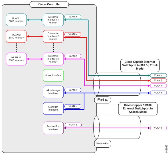
A WLAN associates a service set identifier (SSID) to an interface or an interface group. It is configured with security, quality of service (QoS), radio policies, and other wireless network parameters. Up to 512 WLANs can be configured per controller.

Figure 2. Relationship between Ports, Interfaces, and WLANs

Each controller port connection is an 802.1Q trunk and should be configured as such on the neighbor switch. On Cisco switches, the native VLAN of an 802.1Q trunk is an untagged VLAN. If you configure an interface to use the native VLAN on a neighboring Cisco switch, make sure you configure the interface on the controller to be untagged.


Note


A zero value for the VLAN identifier (on the Controller > Interfaces page) means that the interface is untagged.

The default (untagged) native VLAN on Cisco switches is VLAN 1. When controller interfaces are configured as tagged (meaning that the VLAN identifier is set to a nonzero value), the VLAN must be allowed on the 802.1Q trunk configuration on the neighbor switch and not be the native untagged VLAN.

We recommend that tagged VLANs be used on the controller. You should also allow only relevant VLANs on the neighbor switch’s 802.1Q trunk connections to controller ports. All other VLANs should be disallowed or pruned in the switch port trunk configuration. This practice is extremely important for optimal performance of the controller.


Note


We recommend that you assign one set of VLANs for WLANs and a different set of VLANs for management interfaces to ensure that controllers properly route VLAN traffic.

Management Interface

The management interface is the default interface for in-band management of the controller and connectivity to enterprise services such as AAA servers. It is also used for communications between the controller and access points, for all CAPWAP or intercontroller mobility messaging and tunneling traffic. You can access the GUI of the controller by entering the management interface IP address of the controller in the address field of your browser. The AP management is enabled by default on the management interface.

For CAPWAP, the controller requires one management interface to control all inter-controller communications and one AP-manager interface to control all controller-to-access point communications, regardless of the number of ports.


Note


To prevent or block a wired or wireless client from accessing the management network on a controller (from the wireless client dynamic interface or VLAN), the network administrator should ensure that only authorized clients gain access to the management network through proper CPU ACLs, or use a firewall between the client dynamic interface and the management network.

Caution


Do not map a guest WLAN to the management interface. If the EoIP tunnel breaks, the client could obtain an IP and be placed on the management subnet.

In a High Availability environment with Release 8.0 or a later release, ensure that the management interface and the redundancy management interface (RMI) are tagged for the HA-SSO to work as expected.

This section contains the following subsections:

Configuring the Management Interface (GUI)

Procedure

Step 1

Choose Controller > Interfaces to open the Interfaces page.

Step 2

Click the management link.

The Interfaces > Edit page appears.

Step 3

Set the management interface parameters:

Note

 
The management interface uses the controller’s factory-set distribution system MAC address.
  • Quarantine and quarantine VLAN ID, if applicable

  • VLAN identifier

    Note

     
    Enter 0 for an untagged VLAN or a nonzero value for a tagged VLAN. We recommend using tagged VLANs for the management interface.
  • Configuring Management Interface using IPv4— Fixed IP address, IP netmask, and default gateway.

    • Configuring Management Interface using IPv6—Fixed IPv6 address, prefix-length (interface subnet mask for IPv6) and the link local address of the IPv6 gateway router.

    Note

     
    • In a setup where IPv6 is used, we recommend the APs to be at least one hop away from the controller. As the IPv6 packets are always sent to the Gateway, if the AP and controller are in the same subnet, it increases the packet hops and impacts the performance.

    • Once the primary IPv6 Address, prefix length, and primary IPv6 gateway are configured on the management interface, they cannot be changed back to default values (:: /128).

    • In a setup where IPv6 CAPWAP is used, we recommend that the APs are at least 1 hop away from the controller because all IPv6 traffic is first forwarded to the gateway.

    • A configuration backup must be carried out before configuring IPv6 in case the user wants to revert back to IPv4 only management interface.

  • Physical port assignment

  • Primary and secondary DHCP servers

  • Access control list (ACL) setting, if required

Step 4

Click Save Configuration.

Step 5

If you made any changes to the management or virtual interface, reboot the controller so that your changes take effect.


Configuring the Management Interface (CLI)

Procedure

Step 1

Enter the show interface detailed management command to view the current management interface settings.

Note

 
The management interface uses the controller’s factory-set distribution system MAC address.

Note

 
This command output shows the port MAC address.

Step 2

Enter the config wlan disable wlan-number command to disable each WLAN that uses the management interface for distribution system communication.

Step 3

Enter these commands to define the management interface:

  1. Using IPv4 Address

    • config interface address management ip-addr ip-netmask gateway

    • config interface quarantine vlan management vlan_id

      Note

       
      Use the config interface quarantine vlan management vlan_id command to configure a quarantine VLAN on the management interface.
    • config interface vlan management {vlan-id | 0}

      Note

       
      Enter 0 for an untagged VLAN or a nonzero value for a tagged VLAN. We recommend using tagged VLANs for the management interface.
    • config interface ap-manager management {enable | disable}

      Note

       
      Use the config interface ap-manager management {enable | disable} command to enable or disable dynamic AP management for the management interface.
    • config interface port management primary-port [secondary-port]

    • config interface dhcp management ip-address-of-primary-dhcp-server [ip-address-of-secondary-dhcp-server]

    • config interface acl management access-control-list-name

  2. Using IPv6 Address

    Note

     
    we recommend the APs to be at least one hop away from the controller. As the IPv6 packets are always sent to the Gateway, if the AP and controller are in same subnet, it increases the packet hops and impacts the performance.
    • config ipv6 interface address management primary ip-address prefix-length IPv6_Gateway_Address

      Note

       
      Once the Primary IPv6 Address, Prefix Length, and Primary IPv6 Gateway are configured on the management interface, they cannot be changed back to default values (:: /128). A configuration backup must be carried out before configuring IPv6 in case the user wants to revert back to IPv4 only management interface.
    • config interface quarantine vlan management vlan_id

      Note

       
      Use the config interface quarantine vlan management vlan_id command to configure a quarantine VLAN on the management interface.
    • config interface vlan management {vlan-id | 0}

      Note

       
      Enter 0 for an untagged VLAN or a nonzero value for a tagged VLAN. We recommend using tagged VLANs for the management interface.
    • config interface ap-manager management {enable | disable}

      Note

       
      Use the config interface ap-manager management {enable | disable} command to enable or disable dynamic AP management for the management interface.
    • config interface port management physical-ds-port-number

    • config interface dhcp management ip-address-of-primary-dhcp-server [ip-address-of-secondary-dhcp-server]

    • config ipv6 interface acl management access-control-list-name

Step 4

Enter these commands if you want to be able to deploy your controller behind a router or other gateway device that is using one-to-one mapping network address translation (NAT):

  • config interface nat-address management {enable | disable}

  • config interface nat-address management set public_IP_address

NAT allows a device, such as a router, to act as an agent between the Internet (public) and a local network (private). In this case, it maps the controller's intranet IP addresses to a corresponding external address. The controller’s dynamic AP-manager interface must be configured with the external NAT IP address so that the controller can send the correct IP address in the Discovery Response.

Note

 
These commands are supported for use only with one-to-one-mapping NAT, where each private client has a direct and fixed mapping to a global address. These commands do not support one-to-many NAT, which uses source port mapping to enable a group of clients to be represented by a single IP address.

Step 5

Enter the save config command.

Step 6

Enter the show interface detailed management command to verify that your changes have been saved.

Step 7

If you made any changes to the management interface, enter the reset system command to reboot the controller in order for the changes to take effect.


Virtual Interface

The virtual interface is used to support mobility management, Dynamic Host Configuration Protocol (DHCP) relay, and embedded Layer 3 security such as guest web authentication. It also maintains the DNS gateway host name used by Layer 3 security and mobility managers to verify the source of certificates when Layer 3 web authorization is enabled.

Specifically, the virtual interface plays these two primary roles:

  • Acts as the DHCP server placeholder for wireless clients that obtain their IP address from a DHCP server.

  • Serves as the redirect address for the web authentication login page.

The virtual interface IP address is used only in communications between the controller and wireless clients. It never appears as the source or destination address of a packet that goes out a distribution system port and onto the switched network. For the system to operate correctly, the virtual interface IP address must be set (it cannot be 0.0.0.0), and no other device on the network can have the same address as the virtual interface. Therefore, the virtual interface must be configured with an unassigned and unused gateway IP address. The virtual interface IP address is not pingable and should not exist in any routing table in your network. In addition, the virtual interface cannot be mapped to a physical port.

We recommend that you configure a non-routable IP address for the virtual interface, ideally not overlapping with the network infrastructure addresses or external. Use one of the options proposed on RFC5737, for example, 192.0.2.0/24, 198.51.100.0/24, and 203.0.113.0/24 networks. This is to avoid using an IP address that is assigned to another device or system.

Restrictions

  • All controllers within a mobility group must be configured with the same virtual interface IP address. Otherwise, inter-controller roaming may appear to work, but the handoff does not complete, and the client loses connectivity for a period of time.

  • The first three octets of the IP address assigned to the virtual interface must not overlap with the same octets used for any IP address assigned to other interfaces such as the management, the dynamic interface, and so on, on the controller. This restriction has been addressed through CSCve90626 in Release 8.5.110.0 and later releases.

This section contains the following subsections:

Configuring Virtual Interfaces (GUI)

Procedure

Step 1

Choose Controller > Interfaces to open the Interfaces page.

Step 2

Click Virtual.

The Interfaces > Edit page appears.

Step 3

Enter the following parameters:

  • Any valid unassigned, and unused gateway IP address

  • DNS gateway hostname

    Note

     
    To ensure connectivity and web authentication, the DNS server should always point to the virtual interface. If a DNS hostname is configured for the virtual interface, then the same DNS host name must be configured on the DNS server(s) used by the client.

Step 4

Click Save Configuration.

Step 5

If you made any changes to the management or virtual interface, reboot the controller so that your changes take effect.


Configuring Virtual Interfaces (CLI)

Procedure

Step 1

Enter the show interface detailed virtual command to view the current virtual interface settings.

Step 2

Enter the config wlan disable wlan-number command to disable each WLAN that uses the virtual interface for distribution system communication.

Step 3

Enter these commands to define the virtual interface:

  • config interface address virtual ip-address

    Note

     
    For ip-address , enter a valid, unassigned, and unused gateway IP address.
  • config interface hostname virtual dns-host-name

Step 4

Enter the reset system command. At the confirmation prompt, enter Y to save your configuration changes to NVRAM. The controller reboots.

Step 5

Enter the show interface detailed virtual command to verify that your changes have been saved.


Service-Port Interfaces

The service-port interface controls communications through and is statically mapped by the system to the service port. The service port can be used for out-of-band management.

The service port can obtain an IPv4 address using DHCP, or it can be assigned a static IPv4 address, but a default gateway cannot be assigned to the service-port interface. Static IPv4 routes can be defined through the controller for remote network access to the service port.

If the service port is in use, the management interface must be on a different supernet from the service-port interface.

Similarly, the service port can be statically assigned an IPv6 address or select an IPv6 address using Stateless Address Auto-Configuration (SLAAC). The default gateway cannot be assigned to the service-port interface. Static IPv6 routes can be defined through the controller for remote network access to the service port.


Note


While IPv6 addressing is used along with stateless address auto-configuration, the controller does not perform the subnet verification; however, you must not connect the service-port in the same subnet as the other interfaces in the controller.

Note


This is the only SLAAC interface on the controller, all other interfaces must be statically assigned (just like for IPv4).

Note


User does not require IPv6 static routes to reach service port from the same network, but IPv6 routes requires to access service port from different network. The IPv6 static routes should be as same as IPv4.

The service-port interface supports the following protocols:

  • SSH and Telnet

  • HTTP and HTTPS

  • SNMP

  • FTP, TFTP, and SFTP

  • Syslog

  • ICMP (ping)

  • NTP


Note


TACACS+ and RADIUS are not supported through the service port.


This section contains the following subsections:

Configuring Service-Port Interfaces Using IPv4 (GUI)

Procedure

Step 1

Choose Controller > Interfaces to open the Interfaces page.

Step 2

Click the service-port link to open the Interfaces > Edit page.

Step 3

Enter the Service-Port Interface parameters:

Note

 
The service-port interface uses the controller’s factory-set service-port MAC address.
  • DHCP protocol (enabled)

  • DHCP protocol (disabled) and IP address and IP netmask

Step 4

Click Save Configuration to save your changes.

Step 5

If you made any changes to the management or virtual interface, reboot the controller so that your changes take effect.


Configuring Service-Port Interfaces Using IPv4 (CLI)

Procedure

Step 1

To view the current service-port interface settings, enter this command:

show interface detailed service-port

Note


The service-port interface uses the controller’s factory-set service-port MAC address.

Step 2

Enter these commands to define the service-port interface:

  • To configure the DHCP server, enter this command:

    config interface dhcp service-port enable

  • To disable the DHCP server, enter this command:

    config interface dhcp service-port disable

  • To configure the IPv4 address, enter this command:

    config interface address service-port ip-addr ip-netmask

The service port is used for out-of-band management of the controller. If the management workstation is in a remote subnet, you may need to add a IPv4 route on the controller in order to manage the controller from that remote workstation. To do so, enter this command:

config route add network-ip-addr ip-netmask gateway

To remove the IPv4 route on the controller, enter this command:

config route delete ip_address

Caution


Communication through the management interface might not work as expected if subnet that is added to static route overlaps with other infrastructure or devices.

Step 3

Enter the save config command to save your changes.

Step 4

Enter the show interface detailed service-port command to verify that your changes have been saved.


Configuring Service-Port Interface Using IPv6 (GUI)

Procedure

Step 1

Choose Controller > Interfaces to open the Interfaces page.

Step 2

Click the service-port link to open the Interfaces > Edit page.

Step 3

Enter the Service-Port Interface parameters:

Note

 
The service-port interface uses the controller’s factory-set service-port MAC address. Service Port can be statically assigned an address or select an address using SLAAC.
  • SLACC(enabled)

  • SLACC (disabled) and Primary Address and Prefix Length

Step 4

Click Save Configuration to save your changes.

Step 5

If you made any changes to the management or virtual interface, reboot the controller so that your changes take effect.


Configuring Service-Port Interfaces Using IPv6 (CLI)

Procedure

Step 1

To view the current service-port interface settings, enter this command:

show interface detailed service-port

Note


The service-port interface uses the controller’s factory-set service-port MAC address.

Step 2

Enter these commands to define the service-port interface:

  • To configure the service port using SLACC , enter this command:

    config ipv6 interface slacc service-port enable

  • To disable the service port from using SLACC, enter this command:

    config ipv6 interface slacc service-port disable

  • To configure the IPv6 address, enter this command:

    config ipv6 interface address service-port iipv6_address prefix-length

Step 3

The service port is used for out-of-band management of the controller. If the management workstation is in a remote subnet, you may need to add a route on the controller in order to manage the controller from that remote workstation. To do so, enter this command:

config ipv6 route add network_ipv6_addr prefix-len ipv6_gw_addr

Step 4

To remove the IPv6 route on the controller, enter this command:

config ipv6 route delete network _ipv6 addr

Step 5

Enter the save config command to save your changes.

Step 6

Enter the show interface detailed service-port command to verify that your changes have been saved.


Dynamic Interface

Dynamic interfaces are created by users and designed to be analogous to VLANs for wireless LAN clients. In a LAG setup, the dynamic interface on a controller is conceptually analogous to an SVI on a switch or router associated with a single VLAN and single subnet, although the controller does not have any routing capabilities. A controller can support up to 512 dynamic interfaces (VLANs). Each dynamic interface is individually configured and allows separate communication streams to exist on any or all of a controller’s distribution system ports. A dynamic interface is a Layer 3 interface on the controller to map a WLAN to a particular VLAN and subnet. If DHCP relay is enabled on the controller, then the applicable dynamic interface is used as the relay address. The dynamic interface will also be the interface through which network communication to and from the controller will occur if the destination address is in the same subnet assigned to a dynamic interface. Alternatively, a dynamic interface can also be configured as an AP management interface as well, in place of the default management interface on a separate port in a non-LAG setup. You can assign dynamic interfaces to distribution system ports, WLANs, the Layer 2 management interface, and the Layer 3 AP-manager interface, and you can map the dynamic interface to a backup port.

Management traffic such as Telnet or SSH, HTTP or HTTPS, and so on, can use a dynamic interface as their destination address if management by dynamic interface option is enabled.

You can configure zero, one, or multiple dynamic interfaces on a distribution system port. However, all dynamic interfaces must be on a different VLAN or IP subnet from all other interfaces configured on the port. If the port is untagged, all dynamic interfaces must be on a different IP subnet from any other interface configured on the port.

For information about maximum number of VLANs supported on a controller platform, see the respective controller platform's datasheet.


Note


You must not configure a dynamic interface in the same network as that of Local Mobility Anchor (LMA). If you do so, the GRE tunnel between the controller and LMA does not come up.


This section contains the following subsections:

Prerequisites for Configuring Dynamic Interfaces

While configuring on the dynamic interface of the controller, you must ensure the following:

  • You must use tagged VLANs for dynamic interfaces.

  • You must allocate a dedicated, static IP address for the subnet and VLAN that will be assigned to the dynamic interface.

Restrictions on Configuring Dynamic Interfaces

The following restrictions apply for configuring the dynamic interfaces on the controller:

  • If the SNMP management station is in the same subnet that is assigned to a dynamic interface, then for any SNMP polling, the request should be issued to the IP address assigned to that dynamic interface, rather than the management interface of the controller.

  • If you are using DHCP proxy and/or a RADIUS source interface, ensure that the dynamic interface has a valid routable address. Duplicate or overlapping addresses across controller interfaces are not supported.

  • You must not use ap-manager as the interface name while configuring dynamic interfaces as ap-manager is a reserved name.

Configuring Dynamic Interfaces (GUI)

Procedure

Step 1

Choose Controller > Interfaces to open the Interfaces page.

Step 2

Perform one of the following:

  • To create a new dynamic interface, click New. The Interfaces > New page appears. Go to Step 3.
  • To modify the settings of an existing dynamic interface, click the name of the interface. The Interfaces > Edit page for that interface appears. Go to Step 5.
  • To delete an existing dynamic interface, hover your cursor over the blue drop-down arrow for the desired interface and choose Remove.

Step 3

Enter an interface name and a VLAN ID.

Note

 
You cannot enter ap-manager as the interface name while configuring a dynamic interface as ap-manager is a reserved name.

Step 4

Click Apply to commit your changes. The Interfaces > Edit page is displayed.

Step 5

Configure the following parameters:

  • Guest LAN, if applicable

  • Quarantine and quarantine VLAN ID, if applicable

    Note

     
    Select the Quarantine check box if you want to configure this VLAN as unhealthy or you want to configure network access control (NAC) out-of-band integration. Doing so causes the data traffic of any client that is assigned to this VLAN to pass through the controller.
  • Physical port assignment

  • NAT address

    Note


    Check the Enable NAT Address check box and enter the external NAT IP address if you want to be able to deploy your controller behind a router or other gateway device that is using one-to-one mapping network address translation (NAT). NAT allows a device, such as a router, to act as an agent between the Internet (public) and a local network (private). In this case, it maps the controller’s intranet IP addresses to a corresponding external address. The controller’s dynamic AP-manager interface must be configured with the external NAT IP address so that the controller can send the correct IP address in the Discovery Response.

    The NAT parameters are supported for use only with one-to-one-mapping NAT, where each private client has a direct and fixed mapping to a global address. The NAT parameters do not support one-to-many NAT, which uses source port mapping to enable a group of clients to be represented by a single IP address.

  • Dynamic AP management

    Note


    When you enable this feature, this dynamic interface is configured as an AP-manager interface (only one AP-manager interface is allowed per physical port). A dynamic interface that is marked as an AP-manager interface cannot be used as a WLAN interface.

    Set the APs in a VLAN that is different than the dynamic interface configured on the controller. If the APs are in the same VLAN as the dynamic interface, the APs are not registered on the controller and the “LWAPP discovery rejected” and “Layer 3 discovery request not received on management VLAN” errors are logged on the controller.

  • VLAN identifier

  • Fixed IP address, IP netmask, and default gateway.

    Note

     
    Enter valid IP addresses in these fields.
  • Primary and secondary DHCP servers

  • Access control list (ACL) name, if required

    Note

     
    To ensure proper operation, you must set the Port Number and Primary DHCP Server parameters.

Step 6

Click Save Configuration to save your changes.

Step 7

Repeat this procedure for each dynamic interface that you want to create or edit.


Configuring Dynamic Interfaces (CLI)

Procedure

Step 1

Enter the show interface summary command to view the current dynamic interfaces.

Step 2

View the details of a specific dynamic interface by entering this command:

show interface detailed operator_defined_interface_name .

Note

 
Interface names that contain spaces must be enclosed in double quotes. For example: config interface create "vlan 25"

Step 3

Enter the config wlan disable wlan_id command to disable each WLAN that uses the dynamic interface for distribution system communication.

Step 4

Enter these commands to configure dynamic interfaces:

  • config interface create operator_defined_interface_name {vlan_id | x}

  • config interface address interface ip_addr ip_netmask [gateway]

  • config interface vlan operator_defined_interface_name {vlan_id | o}

  • config interface port operator_defined_interface_name physical_ds_port_number

  • config interface ap-manager operator_defined_interface_name {enable | disable}

    Note


    Use the config interface ap-manager operator_defined_interface_name {enable | disable} command to enable or disable dynamic AP management. When you enable this feature, this dynamic interface is configured as an AP-manager interface (only one AP-manager interface is allowed per physical port). A dynamic interface that is marked as an AP-manager interface cannot be used as a WLAN interface. You cannot use ap-manager as the operator_defined_interface_name while configuring a dynamic interface as ap-manager is a reserved name.

  • config interface dhcp operator_defined_interface_name ip_address_of_primary_dhcp_server [ip_address_of_secondary_dhcp_server]

  • config interface quarantine vlan interface_name vlan_id

    Note

     
    Use the config interface quarantine vlan interface_name vlan_id command to configure a quarantine VLAN on any interface.
  • config interface acl operator_defined_interface_name access_control_list_name

Step 5

Enter these commands if you want to be able to deploy your controller behind a router or other gateway device that is using one-to-one mapping network address translation (NAT):

  • config interface nat-address dynamic-interface operator_defined_interface_name {enable | disable}

  • config interface nat-address dynamic-interface operator_defined_interface_name set public_IP_address

NAT allows a device, such as a router, to act as an agent between the Internet (public) and a local network (private). In this case, it maps the controller’s intranet IP addresses to a corresponding external address. The controller’s dynamic AP-manager interface must be configured with the external NAT IP address so that the controller can send the correct IP address in the Discovery Response.

Note

 
These commands are supported for use only with one-to-one-mapping NAT, whereby each private client has a direct and fixed mapping to a global address. These commands do not support one-to-many NAT, which uses source port mapping to enable a group of clients to be represented by a single IP address.

Step 6

Enter the config wlan enable wlan_id command to reenable each WLAN that uses the dynamic interface for distribution system communication.

Step 7

Enter the save config command to save your changes.

Step 8

Enter the show interface detailed operator_defined_interface_name command and show interface summary command to verify that your changes have been saved.

Note

 
If desired, you can enter the config interface delete operator_defined_interface_name command to delete a dynamic interface.

AP-Manager Interface

A controller configured with IPv4 has one or more AP-manager interfaces, which are used for all Layer 3 communications between the controller and lightweight access points after the access points have joined the controller. The AP-manager IP address is used as the tunnel source for CAPWAP packets from the controller to the access point and as the destination for CAPWAP packets from the access point to the controller.


Note


A controller configured with IPv6 has only one AP-manager and is applicable on management interface. You cannot remove the AP-manager configured on management interface.

Note


The controller does not support jumbo frames. To avoid having the controller transmit CAPWAP packets to the AP that will necessitate fragmentation and reassembly, reduce MTU/MSS on the client side.

A controller configured with IPv6 does not support Dynamic AP-Manager. By default, the management interface acts like an AP-manager interface. Link Aggregation (LAG) is used for IPv6 AP load balancing.

This section contains the following subsections:

Restrictions for Configuring AP Manager Interface

  • For IPv4—The MAC address of the management interface and the AP-manager interface is the same as the base LAG MAC address.

  • An AP-manager interface is not required to be configured. The management interface acts like an AP-manager interface by default, and the access points can join on this interface.

  • If link aggregation (LAG) is enabled, there can be only one AP-manager interface. But when LAG is disabled, one or more AP-manager interfaces can be created, generally one per physical port.

    • When LAG is enabled—Supports only one AP Manager, which can either be on the management or dynamic interface with AP management.

    • When LAG is disabled—Supports one AP Manager per port. The Dynamic Interface tied to a VLAN can act as an AP Manager (when enabled).


      Note


      When you enable LAG, all the ports would lose their AP Manager status and the AP management reverts back onto the Management interface.
  • Port redundancy for the AP-manager interface is not supported. You cannot map the AP-manager interface to a backup port.

  • It is not possible to have APs and a non-AP-manager interface on the same VLAN. If they are in the same VLAN, the controller will move the traffic up on the incorrect VLAN as the controller gets the CAPWAP discovery on the non-AP-manager interface.

Configuring the AP-Manager Interface (GUI)

Procedure

Step 1

Choose Controller > Interfaces to open the Interfaces page.

Step 2

Click AP-Manager Interface.

The Interface > Edit page is displayed.

Note

 
For IPv6 only—A controller configured with IPv6 address does not support Dynamic AP-Manager. By default, the management interface acts like an AP-manager interface.

Step 3

Set the AP-Manager Interface parameters:

Step 4

Click Save Configuration to save your changes.

Step 5

If you made any changes to the management or virtual interface, reboot the controller so that your changes take effect.


Configuring the AP Manager Interface (CLI)

Before you begin

A controller configured with IPv6 address does not support Dynamic AP-Manager. The management interface acts like an AP-manager interface by default.

Procedure

Step 1

Enter the show interface summary command to view the current interfaces.

Step 2

Enter the show interface detailed interface-name command to view the current AP-manager interface settings.

Step 3

Enter the config wlan disable wlan-id command to disable each WLAN that uses the AP-manager interface for distribution system communication.

Step 4

Enter these commands to define the AP-manager interface:

  • config interface address management ip-addr ip-netmask gateway

  • config interface vlan management {vlan-id | 0}

    Note


    Enter 0 for an untagged VLAN or a nonzero value for a tagged VLAN. We recommend using tagged VLANs for the AP-manager interface.

  • config interface port management physical-ds-port-number

  • config interface dhcp management ip-address-of-primary-dhcp-server [ip-address-of-secondary-dhcp-server]

  • config interface acl management access-control-list-name

Step 5

Enter the save config command to save your changes.

Step 6

Enter the show interface detailed interface-name command to verify that your changes have been saved.


Interface Groups

Interface groups are logical groups of interfaces. Interface groups facilitate user configuration where the same interface group can be configured on multiple WLANs or while overriding a WLAN interface per AP group. An interface group can exclusively contain either quarantine or nonquarantine interfaces. An interface can be part of multiple interface groups.

A WLAN can be associated with an interface or interface group. The interface group name and the interface name cannot be the same.

This feature also enables you to associate a client to specific subnets based on the foreign controller that they are connected to. The anchor controller WLAN can be configured to maintain a mapping between foreign controller MAC and a specific interface or interface group (Foreign maps) as needed. If this mapping is not configured, clients on that foreign controller gets VLANs associated in a round robin fashion from interface group configured on WLAN.

You can also configure AAA override for interface groups. This feature extends the current access point group and AAA override architecture where access point groups and AAA override can be configured to override the interface group WLAN that the interface is mapped to. This is done with multiple interfaces using interface groups.

Controller marks VLAN as dirty when the clients are unable to receive IP address using DHCP. The VLAN interface is marked as dirty based on two methods:

Aggressive Method—When only one failure is counted per association per client and controller marks VLAN as dirty interface when a failure occurs three times for a client or for three different clients.

Non-Aggressive Method—When only one failure is counted per association per client and controller marks VLAN as a dirty interface only when three or more clients fail.

This section contains the following subsections:

Restrictions on Configuring Interface Groups

  • The priority order for configuring interface groups for WLAN is:

    • AAA override

    • AP group

    • Interface group


    Note


    AP group interface mapping for a WLAN is not supported in an anchor-foreign scenario.


  • Dual stack clients with a static-IPv4 address is not supported.

Creating Interface Groups (GUI)

Procedure

Step 1

Choose Controller > Interface Groups.

The Interface Groups page appears with the list of interface groups already created.

Note

 
To remove an interface group, hover your mouse pointer over the blue drop-down icon and choose Remove.

Step 2

Click Add Group.

The Add New Interface Group page appears.

Step 3

Enter the details of the interface group:

  • Interface Group Name—Specify the name of the interface group.

  • Description—Add a brief description of the interface group.

Step 4

Click Add.


Creating Interface Groups (CLI)

Procedure

Step 1

config interface group {create | delete} interface_group_name—Creates or deletes an interface group

Step 2

config interface group description interface_group_name description —Adds a description to the interface group


Adding Interfaces to Interface Groups (GUI)

Procedure

Step 1

Choose Controller > Interface Groups.

The Interface Groups page appears with a list of all interface groups.

Step 2

Click the name of the interface group to which you want to add interfaces.

The Interface Groups > Edit page appears.

Step 3

Choose the interface name that you want to add to this interface group from the Interface Name drop-down list.

Step 4

Click Add Interface to add the interface to the Interface group.

Step 5

Repeat Steps 2 and 3 if you want to add multiple interfaces to this interface group.

Note

 
To remove an interface from the interface group, hover your mouse pointer over the blue drop-down arrow and choose Remove.

Adding Interfaces to Interface Groups (CLI)

Procedure

Add interfaces to interface groups by entering this command:

config interface group interface add interface_group interface_name

Viewing VLANs in Interface Groups (CLI)

Procedure

View a list of VLANs in the interface groups by entering this command:

show interface group detailed interface-group-name


Adding an Interface Group to a WLAN (GUI)

Procedure

Step 1

Choose the WLAN tab.

The WLANs page appears listing the available WLANs.

Step 2

Click the WLAN ID of the WLAN to which you want to add the interface group.

Step 3

In the General tab, choose the interface group from the Interface/Interface Group (G) drop-down list.

Step 4

Click Apply.

Note

 
Suppose that the interface group that you add to a WLAN has RADIUS Server Overwrite interface enabled. In this case, when a client requests for authentication, the controller selects the first IP address from the interface group as the RADIUS server.

Adding an Interface Group to a WLAN (CLI)

Procedure

Add an interface group to a WLAN by entering this command:

config wlan interface wlan_id interface_group_name