IPS 5.X and later/IDSM2: Inline VLAN Pair Mode using CLI and IDM Configuration Example
Available Languages
Contents
Introduction
The association of VLANs in pairs on a physical interface is known as inline VLAN pair mode. Packets received on one of the paired VLANs are analyzed and forwarded to the other VLAN in the pair. Inline VLAN pairs are supported on all sensors that are compatible with Intrusion Prevention System (IPS) 5.1, except NM-CIDS, AIP-SSM-10, and AIP-SSM-20.
Inline VLAN pair mode is an active sensing mode where a sensing interface acts as an 802.1q trunk port, and the sensor performs VLAN bridging between pairs of VLANs on the trunk. This means that the switch connected to the sensing interface must be in trunk mode.
The sensor inspects the traffic it receives on each VLAN in each pair, and can either forward the packets on the other VLAN in the pair or drop the packet if an intrusion attempt is detected. You can configure an IPS sensor to simultaneously bridge up to 255 VLAN pairs on each sensing interface. The sensor replaces the VLAN ID field in the 802.1q header of each received packet with the ID of the egress VLAN on which the sensor forwards the packet. The sensor drops all packets received on any VLANs that are not assigned to inline VLAN pairs.
Note: For IPS-4260, fail-open hardware bypass is not supported on inline VLAN pairs. Refer to Hardware Bypass Configuration Restrictions for more information.
Prerequisites
Requirements
There are no specific requirements for this document.
Components Used
The information in this document is based on Cisco Intrusion Prevention System Sensor that uses the 5.1 and later.
The information in this document was created from the devices in a specific lab environment. All of the devices used in this document started with a cleared (default) configuration. If your network is live, make sure that you understand the potential impact of any command.
Related Products
The information in this document is also applicable to the Intrusion Detection System (IDSM-2) Services Module.
Conventions
Refer to Cisco Technical Tips Conventions for more information on document conventions.
VACL Capture Configuration
Refer to the Configuring VACL Capture section of Configuring IDSM-2 in order to send traffic to the IDSM on the switch.
Inline VLAN Pair Mode Configuration
In this section, you are presented with the information to configure the features described in this document.
Note: Use the Command Lookup Tool (registered customers only) to obtain more information on the commands used in this section.
Use the physical-interfaces interface_name command in the service interface submode in order to configure inline VLAN pairs using the CLI. The interface name is FastEthernet or GigabitEthernet.
These options apply:
-
admin-state {enabled | disabled}—The administrative link state of the interface, whether the interface is enabled or disabled.
Note: On all backplane sensing interfaces on all modules (IDSM-2 NM-CIDS, and AIP-SSM), admin-state is set to enabled and is protected (you cannot change the setting). The admin-state has no effect (and is protected) on the command and control interface. It only affects sensing interfaces. The command and control interface does not need to be enabled because it cannot be monitored.
-
default—Sets the value back to the system default setting.
-
description—Your description of the inline interface pair.
-
duplex—The duplex setting of the interface.
-
auto—Sets the interface to auto negotiate duplex.
-
full—Sets the interface to full duplex.
-
half—Sets the interface to half duplex.
Note: The duplex option is protected on all modules.
-
-
no—Removes an entry or selection setting.
-
speed—The speed setting of the interface.
-
auto—Sets the interface to auto negotiate speed.
-
10—Sets the interface to 10 MB (for TX interfaces only).
-
100—Sets the interface to 100 MB (for TX interfaces only).
-
1000—Sets the interface to 1 GB (for Gigabit interfaces)
Note: The speed option is protected on all modules.
-
-
subinterface-type—Specifies that the interface is a subinterface and what type of subinterface is defined.
-
inline-vlan-pair—Lets you define the subinterface as an inline VLAN pair.
-
none—No subinterfaces defined.
-
-
subinterface—Defines the subinterface as an inline VLAN pair.
-
vlan1—The first VLAN in the inline VLAN pair.
-
vlan2—The second VLAN in the inline VLAN pair.
-
CLI Configuration
Complete these steps in order to configure the inline VLAN pair settings on the sensor using CLI:
-
Log in to the CLI using an account with administrator privileges.
-
Enter the interface submode:
sensor#configure terminal
sensor(config)#service interface
sensor(config-int)#
-
Verify if any inline interfaces exist (the subinterface type should read "none" if no inline interfaces have been configured):
sensor(config-int)#show settings physical-interfaces (min: 0, max: 999999999, current: 2) ----------------------------------------------- <protected entry> name: GigabitEthernet0/0 <defaulted> ----------------------------------------------- media-type: tx <protected> description: <defaulted> admin-state: disabled <protected> duplex: auto <defaulted> speed: auto <defaulted> alt-tcp-reset-interface ----------------------------------------------- none ----------------------------------------------- ----------------------------------------------- ----------------------------------------------- subinterface-type ----------------------------------------------- none ----------------------------------------------- ----------------------------------------------- ----------------------------------------------- ----------------------------------------------- <protected entry> name: GigabitEthernet0/1 <defaulted> ----------------------------------------------- media-type: tx <protected> description: <defaulted> admin-state: disabled <defaulted> duplex: auto <defaulted> speed: auto <defaulted> alt-tcp-reset-interface ----------------------------------------------- none ----------------------------------------------- ----------------------------------------------- ----------------------------------------------- subinterface-type ----------------------------------------------- none ----------------------------------------------- ----------------------------------------------- ----------------------------------------------- ----------------------------------------------- <protected entry> name: GigabitEthernet0/2 <defaulted> ----------------------------------------------- media-type: tx <protected> description: <defaulted> admin-state: disabled <defaulted> duplex: auto <defaulted> speed: auto <defaulted> alt-tcp-reset-interface ----------------------------------------------- none ----------------------------------------------- ----------------------------------------------- ----------------------------------------------- subinterface-type ----------------------------------------------- none ----------------------------------------------- ----------------------------------------------- ----------------------------------------------- ----------------------------------------------- <protected entry> name: GigabitEthernet0/3 <defaulted> ----------------------------------------------- media-type: tx <protected> description: <defaulted> admin-state: disabled <defaulted> duplex: auto <defaulted> speed: auto <defaulted> alt-tcp-reset-interface ----------------------------------------------- none ----------------------------------------------- ----------------------------------------------- ----------------------------------------------- subinterface-type ----------------------------------------------- none ----------------------------------------------- ----------------------------------------------- ----------------------------------------------- ----------------------------------------------- <protected entry> name: Management0/0 <defaulted> ----------------------------------------------- media-type: tx <protected> description: <defaulted> admin-state: disabled <protected> duplex: auto <defaulted> speed: auto <defaulted> alt-tcp-reset-interface ----------------------------------------------- none ----------------------------------------------- ----------------------------------------------- ----------------------------------------------- subinterface-type ----------------------------------------------- none ----------------------------------------------- ----------------------------------------------- ----------------------------------------------- ----------------------------------------------- ----------------------------------------------- command-control: Management0/0 <protected> inline-interfaces (min: 0, max: 999999999, current: 0) ----------------------------------------------- ----------------------------------------------- bypass-mode: auto <defaulted> interface-notifications ----------------------------------------------- missed-percentage-threshold: 0 percent <defaulted> notification-interval: 30 seconds <defaulted> idle-interface-delay: 30 seconds <defaulted> ----------------------------------------------- sensor(config-int)# -
Remove any inline interfaces that use this physical interface:
sensor(config-int)#no inline-interfaces interface_name
-
Display the list of available interfaces:
sensor(config-int)#physical-interfaces ?
GigabitEthernet0/0     GigabitEthernet0/0 physical interface.
GigabitEthernet0/1     GigabitEthernet0/1 physical interface.
GigabitEthernet0/2     GigabitEthernet0/2 physical interface.
GigabitEthernet0/3     GigabitEthernet0/3 physical interface.
Management0/0          Management0/0 physical interface.
sensor(config-int)#physical-interfaces
-
Specify an interface:
sensor(config-int)#physical-interfaces GigabitEthernet0/2
-
Enable the admin-state of the interface:
sensor(config-int-phy)#admin-state enabled
The interface must be assigned to the virtual sensor and enabled in order to monitor traffic.
-
Add a description of this interface:
sensor(config-int-phy)#description INT1
-
Configure the duplex settings:
sensor(config-int-phy)#duplex full
This option is not available on modules.
-
Configure the speed:
sensor(config-int-phy)#speed 1000
This option is not available on modules.
-
Set up the inline VLAN pair:
sensor(config-int-phy)#subinterface-type inline-vlan-pair
sensor(config-int-phy-inl)#subinterface 1
sensor(config-int-phy-inl-sub)#vlan1 52
sensor(config-int-phy-inl-sub)#vlan2 53
-
Add a description for the inline VLAN pair:
sensor(config-int-phy-inl-sub)#description pairs vlans 52 and 53
-
Verify the inline VLAN pair settings:
sensor(config-int-phy-inl-sub)#show settings subinterface-number: 1 ----------------------------------------------- description: VLANpair1 default: vlan1: 52 vlan2: 53 ----------------------------------------------- sensor(config-int-phy-inl-sub)# -
Exit the interface submode:
sensor(config-int-phy-inl-sub)#exit
sensor(config-int-phy-inl)#exit
sensor(config-int-phy)#exit
sensor(config-int)#exit
Apply Changes:?[yes]:
-
Press Enter in order to apply the changes, or enter no to discard them.
-
Enter the virtual sensor configuration mode:
sensor(config)#service analysis-engine sensor(config-ana)#virtual-sensor vs0 -
Add the interface to the virtual-sensor:
sensor(config-ana-vir)#physical-interface GigabitEthernet0/2
subinterface-number 1
-
Exit the virtual-sensor submode:
sensor(config-ana-vir)#exit sensor(config-ana)#exit Apply Changes:?[yes]: -
Press Enter in order to apply the changes, or enter no to discard them.
IDM Configuration
Complete these steps to configure the inline VLAN pair settings on the sensor using IDS Device Manager (IDM):
-
Open your browser and enter https://<Management_IP_Address_of_IPS> to access the IDM on the IPS.
-
Click Download IDM Launcher and Start IDM to download the installer for the application.
-
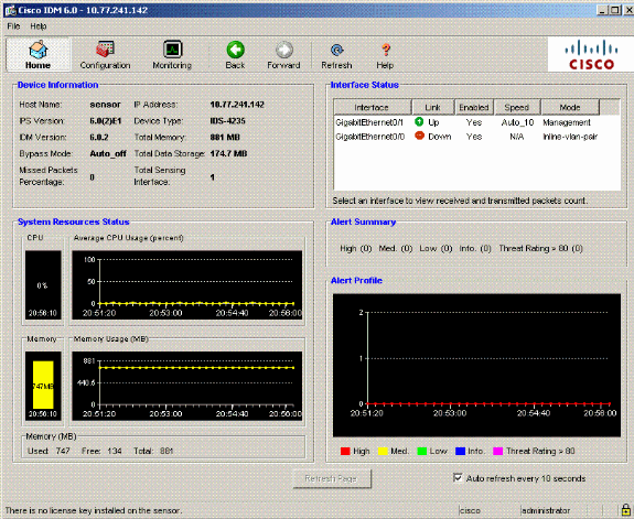
Go to the Home page in order to view the device information such as Host Name, IP Address, version, and the model., etc.
-
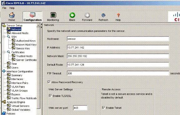
Go to Configuration > Sensor Setup and click Network. Here you can specify the Hostname, IP Address and Default Route.
-
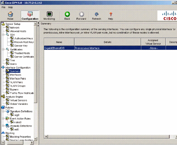
Go to Configuration > Interface Configuration and click Summary.
This page shows the configuration summary of the sensing interface.
-
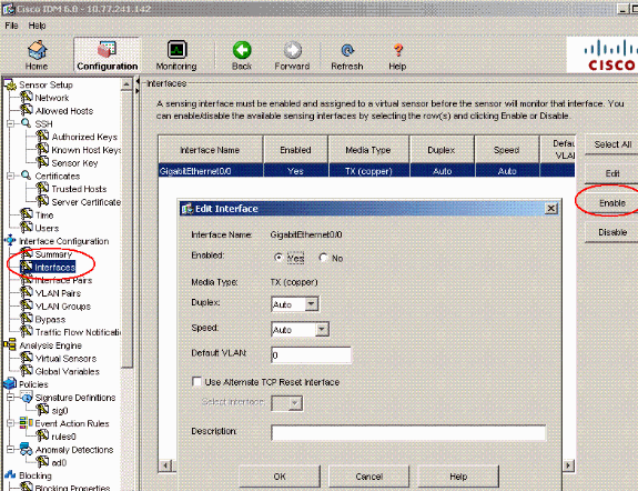
Go to Configuration > Interface Configuration > Interfaces and select the interface name.Then, click Enable in order to enable the sensing interface. Also, configure the Duplex, Speed and VLAN information.
-
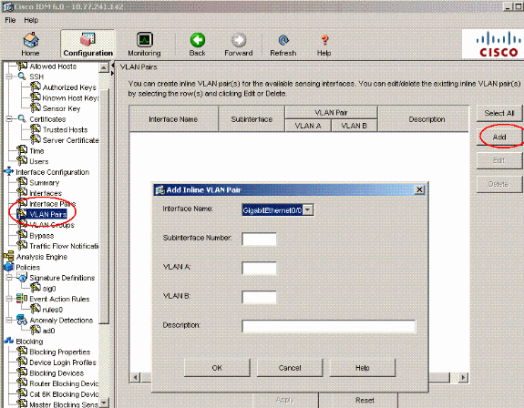
Go to Configuration > Interface Configuration > VLAN Pairs and click Add in order to create the Inline VLAN Pairs.
-
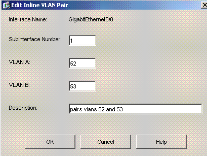
Enter the Subinterface Number, VLAN A and VLAN B for the sensing interface (GigabitEthernet0/0).
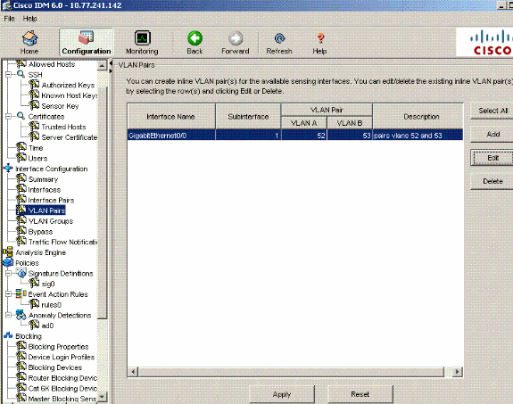
You can view the summary of the Inline VLAN Pair Configuration.
-
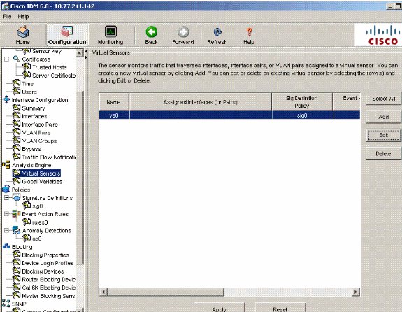
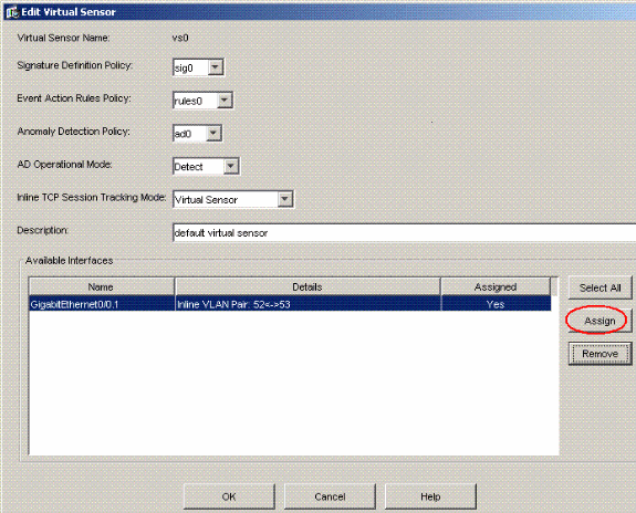
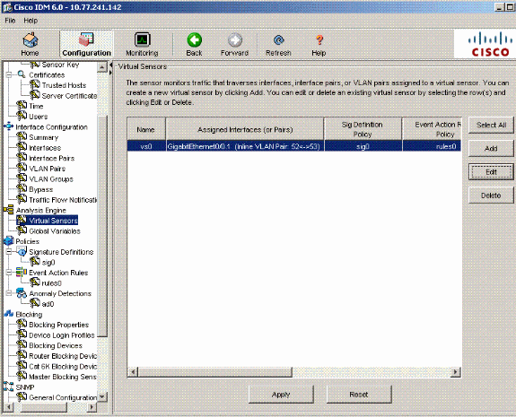
Go to Configuration > Analysis Engine > Virtual Sensor and click Edit in order to create the new virtual sensor.
-
Assign the Inline VLAN Pair 52 and 53 to the Virtual Sensor vs0.
View the summary of the assigned virtual sensor information.
Troubleshoot
There is currently no specific troubleshooting information available for this configuration.
Related Information
Revision History
| Revision | Publish Date | Comments |
|---|---|---|
1.0 |
27-Jun-2007 |
Initial Release |


 Feedback