Unified Communications Manager Express Toll Fraud Prevention
Available Languages
Contents
Introduction
This document provides a configuration guide that can be used in order to help secure a Cisco Communications Manager Express (CME) system and mitigate the threat of toll fraud. CME is Cisco’s router-based call control solution that provides a smart, simple and secure solution for organizations that want to implement Unified Communications. It is highly recommend that you implement the security measures described in this document in order to provide additional levels of security control and reduce the possibility of toll fraud.
The objective of this document is to educate you on the various security tools available on Cisco Voice Gateways and CME. These tools can be implemented on a CME system in order to help mitigate the threat of toll fraud by both internal and external parties.
This document provides instructions on how to configure a CME system with various toll security and feature restriction tools. The document also outlines why certain security tools are used in certain deployments.
The overall inherent flexibility of Cisco’s ISR platforms allows you to deploy CME in many different types of deployments. Thus it can be required to use a combination of the features described in this document to help lock down the CME. This document serves as a guideline for how to apply security tools on CME and in no way guarantees that toll-fraud or abuse by both internal and external parties will not occur.
Prerequisites
Requirements
Cisco recommends that you have knowledge of these topics:
-
Cisco Unified Communications Manager Express
Components Used
The information in this document is based on the Cisco Unified Communications Manager Express 4.3 and CME 7.0.
Note: Cisco Unified CME 7.0 includes the same features as Cisco Unified CME 4.3, which is renumbered to 7.0 to align with Cisco Unified Communications versions.
The information in this document was created from the devices in a specific lab environment. All of the devices used in this document started with a cleared (default) configuration. If your network is live, make sure that you understand the potential impact of any command.
Conventions
Refer to Cisco Technical Tips Conventions for more information on document conventions.
Overview
This document covers the most common security tools that can be used on a CME system to help mitigate the threat of toll fraud. The CME security tools referenced in this document include toll restriction tools and feature restriction tools.
Toll Restriction Tools
-
Direct-inward-dial
-
After-hours toll restriction
-
Class of Restriction
-
Access-list to restrict H323/SIP trunk access
Feature Restriction Tools
-
Transfer-pattern
-
Transfer-pattern blocked
-
Transfer max-length
-
Call-forward max-length
-
No forward local-calls
-
No auto-reg-ephone
Cisco Unity Express Restriction Tools
-
Secure Cisco Unity Express PSTN access
-
Message notification restriction
Call Logging
-
Call logging to capture call detail records (CDRs)
Internal vs. External Threats
This document discusses threats from both internal and external parties. Internal parties include IP phone users that reside on a CME system. External parties include users on foreign systems that can try to use the host CME to make fraudulent calls and have the calls charged back to your CME system.
Toll Restriction Tools
Direct-inward-dial
Abstract
Direct-inward-dial (DID) is used on Cisco voice gateways in order to allow the gateway to process an inbound call after it receives digits from the PBX or CO switch. When DID is enabled, the Cisco gateway does not present a secondary dial tone to the caller and does not wait to collect additional digits from the caller. It forwards the call directly to the destination that matches the inbound Dialed Number Identification Service (DNIS). This is called one-stage dialing.
Note: This is an external threat.
Problem Statement
If direct-inward-dial is NOT configured on a Cisco Gateway or CME, whenever a call comes in from the CO or PBX to the Cisco Gateway, the caller hears a secondary dial-tone. This is called two-stage dialing. Once the PSTN callers hears the secondary dial-tone, they are able to enter digits to reach any internal extension or if they know the PSTN access code, they can dial long-distance or international numbers. This presents a problem because the PSTN caller can use the CME system to place outbound long-distance or international calls and the company gets charged for the calls.
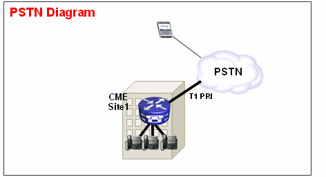
Example 1
At Site 1, the CME is connected to the PSTN through a T1 PRI trunk. The PSTN provider provides the 40855512.. DID range for CME Site 1. Thus all PSTN calls destined for 4085551200 – 4085551299 are routed inbound to the CME. If you do not configure direct-inward-dial on the system, an inbound PSTN caller hears a secondary a dial-tone and must manually dial the internal extension. The bigger problem is that if the caller is an abuser and knows the PSTN access code on the system, commonly 9, they can dial 9 then any destination-number they want to reach.
Solution 1
In order to mitigate this threat, you must configure direct-inward-dial. This causes the Cisco gateway to forward the inbound call directly to the destination that matches the inbound DNIS.
Sample Configuration
dial-peer voice 1 pots
port 1/0:23
incoming called-number .
direct-inward-dial
For DID to work correctly, make sure the inbound call matches the correct POTS dial-peer where the direct-inward-dial command is configured. In this example, the T1 PRI is connected to port 1/0:23. In order to match the correct inbound dial peer, issue the incoming called-number dial peer command under the DID POTS dial peer.
Example 2
At Site 1, the CME is connected to the PSTN through a T1 PRI trunk. The PSTN provider gives the 40855512.. and 40855513.. DID ranges for CME Site 1. Thus all PSTN calls destined for 4085551200 – 4085551299 and 4085551300 - 4085551399 are routed inbound to the CME.
Incorrect Configuration:
If you configure an inbound dial-peer, as in the sample configuration in this section, the possibility for toll fraud still occurs. The problem with this inbound dial-peer is that it only matches inbound calls to 40852512.. and then applies the DID service. If a PSTN call comes into 40852513.., the inbound pots dial-peer does not match and thus the DID service is not applied. If an inbound dial-peer with DID is not matched, then the default dial-peer 0 is used. DID is disabled by default on dial-peer 0.
Sample Configuration
dial-peer voice 1 pots
incoming called-number 40855512..
direct-inward-dial
Correct Configuration
The correct way to configure DID service on an inbound dial-peer is shown in this example:
Sample Configuration
dial-peer voice 1 pots
port 1/0:23
incoming called-number .
direct-inward-dial
Refer to DID Configuration for POTS Dial Peers for more information on DID for digital T1/E1 voice ports.
Note: The use of DID is not needed when Private-Line Automatic Ringdown (PLAR) is used on a voice-port or a service script such as Auto-Attendant (AA) is used on the inbound dial-peer.
Sample Configuration—PLAR
voice-port 1/0
connection-plar 1001
Sample Configuration—Service Script
dial-peer voice 1 pots
service AA
port 1/0:23
After-hours Toll Restrictions
Abstract
After-hours Toll Restriction is a new security tool available in CME 4.3/7.0 that allows you to configure toll restriction policies based on time and date. You can configure policies so that users are not allowed to make calls to predefined numbers during certain hours of the day or all the time. If the 7x24 after-hours call blocking policy is configured, it also restricts the set of numbers that can be entered by an inside user to set call-forward all.
Note: This is an internal threat.
Example 1
This example defines several patterns of digits for which outbound calls are blocked. Patterns 1 and 2, which block calls to external numbers that begin with "1" and "011," are blocked on Monday through Friday before 7 a.m. and after 7 p.m., on Saturday before 7 a.m. and after 1 p.m., and all day Sunday. Pattern 3 blocks calls to 900 numbers 7 days a week, 24 hours a day.
Sample Configuration
 telephony-service
 after-hours block pattern 1 91
 after-hours block pattern 2 9011
 after-hours block pattern 3 91900 7-24
 after-hours day mon 19:00 07:00
 after-hours day tue 19:00 07:00
 after-hours day wed 19:00 07:00
 after-hours day thu 19:00 07:00
 after-hours day fri 19:00 07:00
 after-hours day sat 13:00 07:00
 after-hours day sun 12:00 12:00
Refer to Configuring Call Blocking for more information on toll restriction.
Class of Restriction
Abstract
If you want granular control when you configure toll restriction, you must use Class of Restriction (COR). Refer to Class of Restriction: Example for more information.
H.323 / SIP Trunks toll fraud restrictions
Abstract
In cases where a CME system is connected over a WAN to other CME devices through a SIP or H.323 trunk, you can restrict SIP/H.323 trunk access to the CME in order to prevent abusers from using your system to illegally relay calls to the PSTN.
Note: This is an external threat.
Example 1
In this example, the CME 1 has PSTN connectivity. CME 2 is connected over the WAN to CME 1 through a H.323 trunk. In order to secure the CME 1, you can configure an access-list and apply it inbound on the WAN interface and thus only allow IP traffic from CME 2. This prevents the Rogue IP PBX from sending VOIP calls through CME 1 to the PSTN.
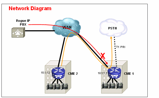
Solution
Do not allow the WAN interface on CME 1 to accept traffic from rogue devices that it does not recognize. Note that there is an implicit DENY all at the end of an access-list. If there are more devices from which you want to allow inbound IP traffic, be sure to add the IP address of the device to the access-list.
Sample Configuration—CME 1
interface serial 0/0
  ip access-group 100 in
!
access-list 100 permit ip 10.1.1.2 255.255.255.255 any
Example 2
In this example, the CME 1 is connected to the SIP provider for PSTN connectivity with the sample configuration provided at Cisco CallManager Express (CME) SIP Trunking Configuration Example.
Since CME 1 is on the public internet, it is possible that toll fraud can occur if a rogue user scans public IP addresses for well known ports for H.323 (TCP 1720) or SIP (UDP or TCP 5060) signaling and sends SIP or H.323 messages that route calls back out of the SIP trunk to the PSTN. Most common abuses in this case are the rogue user makes multiple international calls through the SIP or H.323 trunk and causes the owner of the CME 1 to pay for these toll fraud calls - in some cases thousands of dollars.
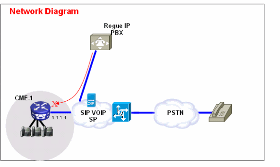
Solution
In order to mitigate this threat, you can use multiple solutions. If any VOIP signaling (SIP or H.323) is not used over the WAN link(s) into CME 1, this must be blocked with the firewall techniques on CME 1 (Access-lists or ACLs) as much as possible.
-
Secure the WAN interface with the Cisco IOS® firewall on CME 1:
This implies that you allow only known SIP or H.323 traffic to come in on the WAN interface. All other SIP or H.323 traffic is blocked. This also requires that you know the IP addresses that the SIP VOIP SP uses for signaling on the SIP Trunk. This solution assumes that the SP is willing to provide all the IP addresses or DNS names they use in their network. Also, if DNS names are used, the configuration requires that a DNS server that can resolve these names is reachable. Also, if the SP changes any addresses on their end, the configuration needs to be updated on CME 1. Note that these lines need to be added in addition to any ACL entries already present on the WAN interface.
Sample Configuration—CME 1
interface serial 0/0
  ip access-group 100 in
!
access-list 100 permit udp host 1.1.1.254 eq 5060 any

!--- 1.1.1.254 is SP SIP proxy

access-list 100 permit udp host 1.1.1.254 any eq 5060
access-list 100 permit udp any any range 16384 32767
-
Ensure calls that come in on the SIP trunk do NOT hairpin back out:
This implies that the CME 1 configuration only allows SIP – SIP hairpin of calls to a specific known PSTN number range, all other calls are blocked. You must configure specific inbound dial-peers for the PSTN numbers that come in on the SIP trunk that are mapped to extensions or auto attendant(s) or voicemail on CME 1. All other calls to numbers that are not part of the CME 1 PSTN number range are blocked. Note, this does not affect call forwards / transfers to voicemail (Cisco Unity Express) and call forward all to PSTN numbers from IP phones on CME 1, because the initial call is still targeted towards an extension on CME 1.
Sample Configuration—CME 1
dial-peer voice 1000 voip
  description ** Incoming call to 4085551000 from SIP trunk **
  voice-class codec 1
  voice-class sip dtmf-relay force rtp-nte
  session protocol sipv2
  incoming called-number 4085551000
  dtmf-relay rtp-nte
  no vad
!
dial-peer voice 1001 voip
  permission term

 !--- Prevent hairpinning calls back over SIP Trunk.

  description ** Incoming call from SIP trunk **
  voice-class codec 1
  voice-class sip dtmf-relay force rtp-nte
  session protocol sipv2
  incoming called-number .T

 !--- Applies to all other inbound calls.

  dtmf-relay rtp-nte
  no vad
-
Use translation rules in order to block specific dial strings:
Most toll frauds involve international call dialing. As a result, you can create a specific inbound dial-peer that matches specific dialed strings and blocks calls to them. Most CMEs use a specific access code, such as 9, to dial out and the international dialing code in the US is 011. Therefore, the most common dial string to block in the US is 9011 + any digits after that come in on the SIP trunk.
Sample Configuration—CME 1
voice translation-rule 1000
 rule 1 reject /^9011/
 rule 2 reject /^91900…….$/
 rule 3 reject /^91976…….$/
!
voice translation-profile BLOCK
translate called 1000
!
dial-peer voice 1000 voip
description ** Incoming call from SIP trunk **
incoming called-number 9011T
call-block translation-profile incoming BLOCK
Feature Restriction Tools
Transfer Pattern
Abstract
Transfers to all numbers except those on local SCCP IP phones are automatically blocked by default. During configuration, you can allow transfers to non local numbers. The transfer-pattern command is used in order to allow the transfer of telephony calls from Cisco SCCP IP phones to phones other than Cisco IP Phones, such as external PSTN calls or phones on another CME system. You can use the transfer-pattern in order to limit the calls to internal extensions only or perhaps limit calls to PSTN numbers in a certain area code only. These examples show how the transfer-pattern command can be used to limit calls to different numbers.
Note: This is an internal threat.
Example 1
Allow users to transfer calls out to only the 408 area code. In this example, the assumption is that the CME is configured with a dial-peer that has a destination-pattern of 9T.
Sample Configuration
telephony-service
transfer-pattern 91408
Transfer-Pattern Blocked
Abstract
In Cisco Unified CME 4.0 and later versions, you can prevent individual phones from transferring calls to numbers that are globally enabled for transfer. The transfer-pattern blocked command over-rides the transfer-pattern command and disables call transfer to any destination that needs to be reached by a POTS or VoIP dial-peer. This includes PSTN numbers, other voice gateways and Cisco Unity Express. This ensures that individual phones do not incur toll charges when calls are transferred outside the Cisco Unified CME system. Call transfer blocking can be configured for individual phones or configured as part of a template that is applied to a set of phones.
Note: This is an internal threat.
Example 1
In this sample configuration, ephone 1 is not allowed to use transfer-pattern (defined globally) to transfer calls, while ephone 2 can use the transfer-pattern defined under telephony-service to transfer calls.
Sample Configuration
ephone-template 1
transfer-pattern blocked
!
ephone 1
ephone-template 1
!
ephone 2
!
Transfer max-length
Abstract
The transfer max-length command specifies the maximum number of digits the user can dial when a call is transferred. The transfer-pattern max-length over-rides the transfer-pattern command and enforces maximum digits allowed for transfer destination. The argument specifies the number of digits allowed in a number to which a call is transferred. Range: 3 to 16. Default: 16.
Note: This is an internal threat.
Example 1
This configuration only allows phones that have this ephone-template applied to transfer to destinations that are a maximum of four digits long.
Sample Configuration
ephone-template 1
transfer max-length 4
Call Forward max-length
Abstract
In order to restrict the number of digits that can be entered with the CfwdALL soft key on an IP phone, use the call-forward max-length command in ephone-dn or ephone-dn-template configuration mode. In order to remove a restriction on the number of digits that can be entered, use the no form of this command.
Note: This is an internal threat.
Example 1
In this example, directory extension 101 is allowed to perform a call-forward to any extension that is one to four digits in length. Any call-forwards to destinations longer than four digits fail.
Sample Configuration
ephone-dn  1  dual-line
number 101
call-forward max-length 4
or
ephone-dn-template  1
call-forward max-length 4
No Forward Local Call
Abstract
When the no forward local-calls command is used in ephone-dn configuration mode, internal calls to a particular ephone-dn with no forward local-calls applied are not forwarded if the ephone-dn is busy or does not answer. If an internal caller rings this ephone-dn and the ephone-dn is busy, the caller hears a busy signal. If an internal caller rings this ephone-dn and it does not answer, the caller hears a ringback signal. The internal call is not forwarded even if call forwarding is enabled for the ephone-dn.
Note: This is an internal threat.
Example 1
In this example, extension 2222 calls extension 3675 and hears a ringback or a busy signal. If an external caller reaches extension 3675 and there is no answer, the call is forwarded to extension 4000.
Sample Configuration
ephone-dn  25
number 3675
no forward local-calls
call-forward noan 4000 timeout 30
Disable Auto-Registration on CME System
Abstract
When auto-reg-ephone is enabled underneath telephony-service on a SCCP CME system, new IP phones that are plugged into the system are auto registered and if auto assign is configured to automatically assign extension numbers, then a new IP phone is able to make calls immediately.
Note: This is an internal threat.
Example 1
In this configuration, a new CME system is configured so that you must manually add an ephone in order for the ephone to register to the CME system and use it to make IP telephony calls.
Solution
You can disable auto-reg-ephone underneath telephony-service so that new IP phones connected to a CME system do not auto register to the CME system.
Sample Configuration
telephony-service
no auto-reg-ephone
Example 2
If you use SCCP CME and plan to register Cisco SIP phones to the system, you must configure the system so that the SIP endpoints have to authenticate with a username and password. In order to do so, simply configure this:
voice register global
 mode cme
 source-address 192.168.10.1 port 5060
 authenticate register
Refer to SIP: Setting Up Cisco Unified CME for a more comprehensive configuration guide for SIP CME.
Cisco Unity Express Restriction Tools
Secure Cisco Unity Express: AA PSTN access
Abstract
When your system is configured so that inbound calls are forwarded to auto-attendant (AA) on Cisco Unity Express, it may be necessary to disable external transfer to the PSTN from Cisco Unity Express AA. This does not allow external users to dial outbound to external numbers after they reach Cisco Unity Express AA.
Note: This is an external threat.
Note: Solution
Note: Disable the allowExternalTransfers option on the Cisco Unity Express GUI.
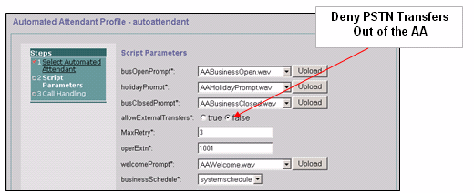
Note: If PSTN access from the AA is required, limit the numbers or range of numbers that are considered valid by the script.
Cisco Unity Express Restriction Tables
Abstract
You can use the Cisco Unity Express restriction tables in order to restrict the destinations that can be reached during an outcall from Cisco Unity Express. The Cisco Unity Express restriction table can be used in order to prevent toll fraud and malicious use of the Cisco Unity Express system to make outbound calls. If you use the Cisco Unity Express restriction table, you can specify call patterns to wild card match. Applications that use the Cisco Unity Express restriction table include:
-
Fax
-
Cisco Unity Express Live Replay
-
Message Notification
-
Non-Subscriber Message Delivery
Note: This is an internal threat.
Solution
In order to restrict the destination patterns that can be reached by Cisco Unity Express on an outbound external call, configure the Call Pattern in the System > Restrictions Tables from the Cisco Unity Express GUI.
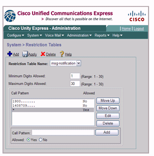
Call Logging
Enhanced CDR
You can configure the CME system to capture enhanced CDR and log the CDR to the router flash or an external FTP server. These records can then be used to retrace calls to see if abuse by internal or external parties has occurred.
The file accounting feature introduced with CME 4.3/7.0 in Cisco IOS Release 12.4(15)XY provides a method to capture accounting records in comma separated value (.csv) format and store the records to a file in internal flash or to an external FTP server. It expands gateway accounting support, which also includes the AAA and syslog mechanisms of logging accounting information.
The accounting process collects accounting data for each call leg created on a Cisco voice gateway. You can use this information for post processing activities such as to generate billing records and for network analysis. Cisco voice gateways capture accounting data in the form of call detail records (CDRs) that contain attributes defined by Cisco. The gateway can send CDRs to a RADIUS server, syslog server, and with the new file method, to flash or an FTP server in .csv format.
Refer to CDR Examples for more information on the Enhanced CDR capabilities.
Related Information
- Cisco Unified Communications Manager Express Security Best Practices
- Cisco Communications Manager Express Administrators Guide
- Cisco Communications Manager Express Administrators Guide – Call Blocking
- Understanding Dial-Peer Matching on IOS platforms
- Number Translation using Voice Translation Profiles
- CME Solution Reference Network Design Guide
- Technical Support & Documentation - Cisco Systems
Contact Cisco
- Open a Support Case

- (Requires a Cisco Service Contract)
 Feedback