Making a Management Cable for the Cisco 600 Series CPE
Available Languages
Contents
Introduction
This document describes the pinouts used for making a management cable for the Cisco 600 series Customer Premises Equipment (CPE). The cable allows the user to manage and configure the Cisco 600 from a Windows PC running HyperTerminal. This document specifically covers PCs that have a communications port (COM port) with a DB-9 serial port connector and the Cisco 600 CPE, which has an RJ-45 serial port.
Before You Begin
Conventions
For more information on document conventions, see the Cisco Technical Tips Conventions.
Prerequisites
There are no specific prerequisites for this document.
Components Used
The information in this document is based on the hardware versions below.
-
RJ-45 male connector
-
High quality cable, such as category 5
-
DB-9 female connector
The information presented in this document was created from devices in a specific lab environment. All of the devices used in this document started with a cleared (default) configuration. If you are working in a live network, ensure that you understand the potential impact of any command before using it.
Background Theory
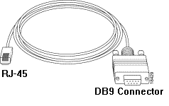
The following is a typical management cable shipped with the Cisco 600 CPE.

Making a Management Cable
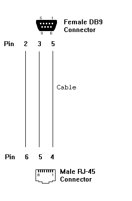
Using the required connectors and cable, build a management cable using the following diagram as a guide.

Using a Management Cable
Step-by-Step Instructions
When you finish building the management cable, follow the steps below to properly use it.
-
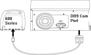
Connect the cable's DB-9 female connector to the DB-9 (male) serial COM port of your PC.
-
Connect the cable's RJ-45 male connector to the management port (labeled "MGMT") of your Cisco 600 CPE.

-
Configure your terminal access program (such as HyperTerminal in Windows) with the following settings:
-
COM port: Port into which you plug the cable.
-
Baud rate: 38400 bps - recommended (standard 9600 bps possible)
-
Data bits: 8
-
Parity: None
-
Stop bits: 1
-
Flow control: None
-
-
Press Enter until you see the prompt (such as cbos>, modem1> or usa>). When you see the prompt, the PC and CPE are communicating.
Note: If the computer has only a DB-25 serial port, a DB-9 to DB-25 adapter is also needed. Also, the same cable can be used to connect a dumb terminal to the Cisco 600 management port.
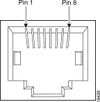
Management Port Connector Pinouts

Serial Port Connector Pinouts
Standard PC DB-9 Serial Port

DB-9 Male Pinouts
| Pin | Function |
|---|---|
| 1 | Data Carrier Detect (CD) |
| 2 | Receive Data (RD) |
| 3 | Transmitted Data (TD) |
| 4 | Data Terminal Ready (DTR) |
| 5 | Signal Ground (GND) |
| 6 | Data Set Ready (DSR) |
| 7 | Request To Send (RTS) |
| 8 | Clear To Send (CTS) |
| 9 | Ring Indicator (RI) |
Verify
There is currently no verification procedure available for this configuration.
Troubleshoot
There is currently no specific troubleshooting information available for this configuration.

 Feedback