What is APPN?
Available Languages
Contents
Introduction
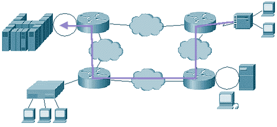
Figure 1

Advanced Peer-to-Peer Networking (APPN) is the second generation of Systems Network Architecture (SNA). It was developed by IBM to meet these requirements:
-
To provide an effective routing protocol to allow SNA traffic to flow natively and concurrently with other protocols.
-
To allow sessions to be established between the end users without involvement of the mainframe.
-
To reduce excessive requirements to predict resources and paths.
-
To maintain a class of service (CoS) and to provide prioritization within SNA traffic.
-
To provide an environment that supports both legacy and APPN traffic.
Prerequisites
Requirements
There are no specific prerequisites for this document. Refer to IBM Document SNA Technical Overview (GC30-3073-04) ![]() for more detailed information on APPN.
for more detailed information on APPN.
Components Used
This document is not restricted to specific software or hardware versions.
Conventions
For more information on document conventions, refer to the Cisco Technical Tips Conventions.
Defining APPN
-
APPN provides peer-to-peer networking; it dynamically locates and defines resources and routes. Sessions can be established between any two logical units in the network, without the involvement of a mainframe.
-
Directory services are distributed. A Network Node (NN) needs to remember only the resources that use its services. However, it is possible to centralize directory services on virtual telecommunications access method (VTAM).
-
Each APPN router maintains a complete map of the network topology that includes all NNs (routers) and links. This allows each router to select the best path through the network at any time, based on the CoS. The topology is updated as changes in the network occur.
-
CoS is carried forward from the legacy SNA and is improved. In APPN, CoS actually extends out to the end nodes in the network rather than just between front-end processors (FEPs), as it did in legacy SNA. Additionally, CoS can now be defined at a much more granular level with explicit definitions of line speeds, cost, and other characteristics.
APPN Terminology
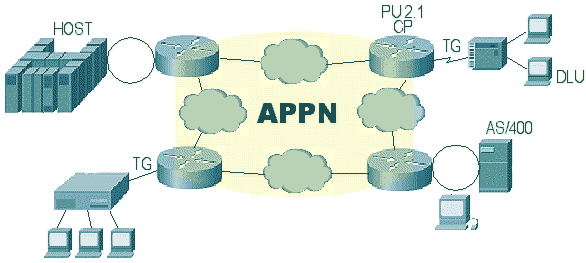
Figure 2

-
Transmission Group (TG)???Refers to the same thing in both APPN terminology and legacy SNA: the set of lines that connect two adjacent nodes. The difference is that the current APPN architecture limits a TG to a single link, although multi-link TGs are expected to be implemented in the future. The topology database contains NNs and TGs, the links that connect NNs.
-
Dependent Logical Units???Legacy logical units (LUs) in types 0, 1, 2, 3, and so forth. They can not initiate sessions without the intervention of VTAM and they can not participate actively in a peer-to-peer session initiation.
-
Physical Unit 2.1 (PU 2.1)???The Physical Unit type for peer-to-peer processing.
-
Control point (CP)???A main component of an APPN node. The CP is responsible for the management of the APPN node. It activates the links to adjacent nodes, activates the CP-CP sessions with other nodes, locates network resources, and collects and exchanges topology information with other nodes.
Types of APPN Nodes
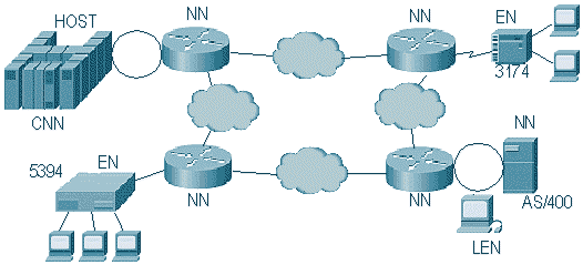
Figure 3

-
Network Node (NN)???A router in an APPN network. Other resources go to the NN when activation of sessions and location of resources are required.
-
End Node (EN)???Can be thought of as an application host, which accesses the network via its NN server. An EN contains a subset of APPN functionality; it does not have functions like network topology, maintenance, and rerouting.
-
Low Entry Node (LEN)???The original peer node that IBM defined for AS/400s and S/36s. It allowed communication between two nodes with the intervention of VTAM. Unfortunately, it did not provide for immediate routing, so relay applications or direct connections were required. APPN nodes are the extensions added to LEN nodes to provide this added functionality. LEN nodes can access an APPN network through an NN server, but resources must be predefined.
-
Composite Network Node (CNN)???Invented to describe the APPN functionality that is implemented in VTAM and in Network Control Program (NCP). VTAM can be a standalone NN, but NCP can not. Therefore, when they work together, they can represent a single NN.
-
Branch Network Node (BrNN)???Appears as an EN to an upstream NN while it provides NN services for downstream ENs and LENs. This support for BrNN is also commonly referred to as Branch Extender (BX). The BX function eliminates APPN topology and APPN broadcast search flows between APPN NNs and the SNA application hosts in the network, which makes the APPN network much more scalable. Cisco???s current APPN implementation, SNASwitch, replaces the legacy APPN implementation from 12.1 and uses BX.
Network Connection
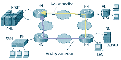
Figure 4

An EN can connect to an NN; or two NNs can connect dynamically, without the need to define everything prior to the connection. There are three steps in this process:
-
Once the physical connection between the adjacent nodes is established, the two nodes exchange basic information???such as name, node type, and pacing support???through an Exchange ID (XID) type 3.
-
After this exchange, parallel LU 6.2 sessions can be established between the control points of the two nodes. This is required between an EN and its NN server and is optional between NNs. Once established, this session is used to send control information, like Topology Updates, between nodes.
-
Once the CP-CP session is established, the topology flows across the network interface. Updates continue to flow as changes occur in the network.
 Feedback