OSPFv3 Virtual Link Configuration Example
Available Languages
Contents
Introduction
This document provides a example on configuring the virtual links in Open Shortest Path First Version 3 (OSPFv3). OSPFv3 expands on OSPF version 2 to provide support for IPv6 routing prefixes and the larger size of IPv6 addresses.
For each virtual link, a master security information datablock is created for the virtual link. Because a secure socket must be opened on each interface, there will be a corresponding security information datablock for each interface in the transit area. The secure socket state is kept in the interface's security information datablock. The state field in the master security information datablock reflects the status of all of the secure sockets opened for the virtual link. If all of the secure sockets are UP, then the security state for the virtual link will be set to UP.
Packets sent on a virtual link with IPsec must use predetermined source and destination addresses. The first local area address found in the router's intra-area-prefix LSA for the area is used as the source address. This source address is saved in the area data structure and used when secure sockets are opened and packets sent over the virtual link. The virtual link will not transition to the point-to-point state until a source address is selected. Also, when the source or destination address changes, the previous secure sockets must be closed and new secure sockets opened.
This configuration example uses the area virtual-link command to define an OSPF virtual link in the router configuration mode.
Note: Each virtual link neighbor must include the transit area ID and the corresponding virtual link neighbor router ID in order for a virtual link to be properly configured. Use the show ip ospf EXEC command to see the router ID.
Prerequisites
Requirements
Ensure that you meet these requirements before you attempt this configuration:
-
Complete the OSPF network strategy and planning for your IPv6 network.
-
Enable IPv6 unicast routing.
-
Enable IPv6 on the interface.
Components Used
This document is not restricted to specific software and hardware versions.
The configurations in this document is based on the Cisco 3700 series router on Cisco IOS® Software Release software 12.4 (15)T 13.
Conventions
Refer to Cisco Technical Tips Conventions for more information on document conventions.
Configure
In this section, you are presented with the information to configure the features described in this document.
Note: Use the Command Lookup Tool (registered customers only) to find more information on the commands used in this document.
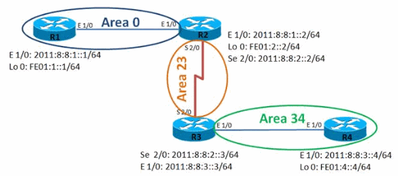
Network Diagram
This document uses this network setup:

Configurations
This document uses these configurations:
-
Router R1
-
Router R2
-
Router R3
-
Router R4
| Router R1 |
|---|
hostname R1 ! ipv6 unicast-routing ipv6 cef ! interface Loopback0 no ip address ipv6 address FE01:1::1/64 ipv6 enable ipv6 ospf 10 area 0 ! interface Ethernet1/0 no ip address ipv6 address 2011:8:8:1::1/64 ipv6 enable ipv6 ospf 10 area 0 ! ipv6 router ospf 10 router-id 1.1.1.1 log-adjacency-changes |
| Router R2 |
|---|
hostname R2 ! ipv6 unicast-routing ipv6 cef ! interface Loopback0 no ip address ipv6 address FE01:2::2/64 ipv6 enable ipv6 ospf 10 area 0 ! interface Ethernet1/0 no ip address ipv6 address 2011:8:8:1::2/64 ipv6 enable ipv6 ospf 10 area 0 ! interface Serial2/0 no ip address ipv6 address 2011:8:8:2::2/64 ipv6 enable ipv6 ospf 10 area 23 serial restart-delay 0 clock rate 64000 ! ipv6 router ospf 10 router-id 2.2.2.2 log-adjacency-changes area 23 virtual-link 3.3.3.3 ! |
| Router R3 |
|---|
hostname R3 ! ipv6 unicast-routing ipv6 cef ! interface Loopback0 no ip address ipv6 address FE01:3::3/64 ipv6 enable ipv6 ospf 10 area 23 ! interface Ethernet1/0 no ip address ipv6 address 2011:8:8:3::3/64 ipv6 enable ipv6 ospf 10 area 34 ! interface Serial2/0 no ip address ipv6 address 2011:8:8:2::3/64 ipv6 enable ipv6 ospf 10 area 23 serial restart-delay 0 ! ipv6 router ospf 10 router-id 3.3.3.3 log-adjacency-changes area 23 virtual-link 2.2.2.2 ! |
| Router R4 |
|---|
hostname R4 ! ipv6 unicast-routing ipv6 cef ! interface Loopback0 no ip address ipv6 address FE01:4::4/64 ipv6 enable ipv6 ospf 10 area 34 ! interface Ethernet1/0 no ip address ipv6 address 2011:8:8:3::4/64 ipv6 enable ipv6 ospf 10 area 34 ! ipv6 router ospf 10 router-id 4.4.4.4 log-adjacency-changes ! |
Verify
Use these commands to verify the configuration:
In Router R1
The output clearly shows that the router R1 can ping successfully the loopback address of the router R4.
| ping ipv6 |
|---|
R1#ping ipv6 Target IPv6 address: fe01:4::4 Ping Loopback 0 interface of R4 Repeat count [5]: Datagram size [100]: Timeout in seconds [2]: Extended commands? [no]: Type escape sequence to abort. Sending 5, 100-byte ICMP Echos to FE01:4::4, timeout is 2 seconds: !!!!! Success rate is 100 percent (5/5), round-trip min/avg/max = 48/72/96 ms |
In Router R2
The show ipv6 ospf neighbor command provides neighbor information on a per interface basis.
| show ipv6 ospf neighbor |
|---|
R2# show ipv6 ospf neighbor

Neighbor ID     Pri   State           Dead Time   Interface ID    Interface
3.3.3.3                 0   FULL/  -                -                22        OSPFv3_VL0

Virtual Link Between R2 & R3

1.1.1.1                 1   FULL/DR         00:00:35         4                 Ethernet1/0
3.3.3.3 0 FULL/ - 00:00:31 12 Serial2/0 |
In Router R4
The output clearly shows that the router R4 can ping successfully the loop back interface of router R1.
| ping ipv6 |
|---|
R4#ping ipv6 Target IPv6 address: fe01:1::1 Ping Loopback 0 interface of R1 Repeat count [5]: Datagram size [100]: Timeout in seconds [2]: Extended commands? [no]: Type escape sequence to abort. Sending 5, 100-byte ICMP Echos to FE01:1::1, timeout is 2 seconds: !!!!! Success rate is 100 percent (5/5), round-trip min/avg/max = 56/100/224 ms |
Troubleshoot
There is currently no specific troubleshooting information available for this configuration.
Related Information
Revision History
| Revision | Publish Date | Comments |
|---|---|---|
1.0 |
24-Aug-2011 |
Initial Release |
Contact Cisco
- Open a Support Case

- (Requires a Cisco Service Contract)
 Feedback