Understanding Multiprotocol Label Switching (MPLS) Label Imposition in an ATM Environment
Available Languages
Contents
Introduction
This document describes the path used by an IP packet when it travels through an MPLS-enabled ATM core and describes the major show commands.
Note: The routers in this document are from the Cisco 3600 series that run Cisco IOS® Version 12.0(7)T and use OC-3 interfaces. The ATM LSR is an 8540MSR.
Prerequisites
Requirements
There are no specific requirements for this document.
Conventions
Refer to Cisco Technical Tips Conventions for more information on document conventions.
Network Diagram
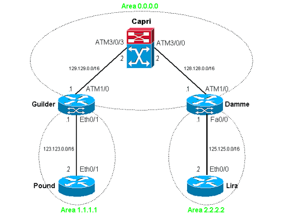
The scenarios in this document are based on this setup. In order to view the configurations for these devices, refer to this sample configuration.

Show Commands
Guilder
Guilder is an interesting router in this setup since it imposes labels to the IP packets that come from the Ethernet side. Since we work on an ATM interface that is connected to an MPLS-enabled ATM core, the imposed label means a forwarded IP packet on a Tag VC (TVC).
In this scenario, Pound sends IP packets to Lira. For example, if you ping 125.125.0.2 from Pound, it works as expected:
Pound#ping 125.125.0.2
Type escape sequence to abort.
Sending 5, 100-byte ICMP Echos to 125.125.0.2, timeout is 2 seconds:
!!!!!
Success rate is 100 percent (5/5), round-trip min/avg/max = 1/2/4 ms
From Guilder's routing table, we can easily see that the destination can be reached through the ATM cloud:
Guilder#show ip route 125.125.0.2
Routing entry for 125.125.0.0/16
  Known via "ospf 1", distance 110, metric 12, type inter area
  Redistributing via ospf 1
  Last update from 129.129.0.2 on ATM1/0.1, 01:15:26 ago
  Routing Descriptor Blocks:
  * 129.129.0.2, from 120.120.0.1, 01:15:26 ago, via ATM1/0.1
      Route metric is 12, traffic share count is 1
We have configured the ATM subinterface 1/0.1 to label the outbound IP packets, so we can receive more details through the Tag forwarding table:
Guilder#show tag-switching forwarding-table 125.125.0.2 detail
Local  Outgoing    Prefix            Bytes tag  Outgoing   Next Hop
tag    tag or VC   or Tunnel Id      switched   interface
30     2/36        125.125.0.0/16    0          AT1/0.1    point2point
        MAC/Encaps=4/8, MTU=4470, Tag Stack{2/36(vcd=299)}
        012B0900 0012B000
We see now that Guilder imposes the outbound TVC VPI 2, VCI 36, which corresponds to VCD 299. This information is saved in the CEF forwarding table:
Guilder#show ip cef 125.125.0.2 detail
125.125.0.0/16, version 143, cached adjacency to ATM1/0.1
0 packets, 0 bytes
  tag information set
    local tag: 30
    fast tag rewrite with AT1/0.1, point2point, tags imposed: {2/36(vcd=299)}
  via 129.129.0.2, ATM1/0.1, 0 dependencies
    next hop 129.129.0.2, ATM1/0.1
    valid cached adjacency
    tag rewrite with AT1/0.1, point2point, tags imposed: {2/36(vcd=299)}
The IP packets are indeed sent on the right VC:
Guilder#show atm vc 299
ATM1/0.1: VCD: 299, VPI: 2, VCI: 36
UBR, PeakRate: 155000
AAL5-MUX, etype:0x8847, Flags: 0x40C84, VCmode: 0x0
OAM frequency: 0 second(s)
InARP DISABLED
Transmit priority 0
InPkts: 0, OutPkts: 5, InBytes: 0, OutBytes: 540
InPRoc: 0, OutPRoc: 0
InFast: 0, OutFast: 5, InAS: 0, OutAS: 0
InPktDrops: 0, OutPktDrops: 0
CrcErrors: 0, SarTimeOuts: 0, OverSizedSDUs:
0OAM cells received:
0OAM cells sent: 0
Status: UP
Tag VC: local tag: 0
As you see, only five IP packets have been sent. This is synchronized with the simple ping that we initiated. At the same time, you can wonder why we do not see five input packets. In other words, why are the outbound and inbound paths different? This is normal since there is one VC per route entry (per prefix), and, as a result, the TVCs are unidirectional.
Capri
Surprisingly, there is not much we can get from the switch when all routes/VCs are stable; it merely switches ATM cells. See this example:
Capri#show tag atm-tdp bindings 125.125.0.0 16
 Destination: 125.125.0.0/16
    Transit ATM3/0/3 2/36 Active -> ATM3/0/0 2/38 Active
Some details must be pointed out. Examine this output:
Capri#show atm vc conn-type tvc int atm 3/0/3
Interface         VPI  VCI   Type   X-Interface      X-VPI X-VCI Encap  Status
ATM3/0/3          2    33    TVC(I) ATM3/0/0          2    36           UP
ATM3/0/3          2    33    TVC(O) ATM3/0/0          2    53           UP
ATM3/0/3          2    34    TVC(I) ATM0              0    317   MUX    UP
ATM3/0/3          2    34    TVC(O) ATM3/0/0          2    54           UP
ATM3/0/3          2    35    TVC(I) ATM3/0/0          2    37           UP
ATM3/0/3          2    35    TVC(O) ATM3/0/0          2    55           UP
ATM3/0/3          2    36    TVC(I) ATM3/0/0          2    38           UP
ATM3/0/3          2    37    TVC(I) ATM0              0    318   MUX    UP
As we can see, some TVCs end on the interface ATM0. On a 8540MSR, the interface ATM0 corresponds to the CPU. Those TVCs correspond to IP addresses local to the 8540MSR, such as a local loopback.
We know that Guilder sends IP packets with destination 125.125.0.2 on TVC 2/36. On the LSR side, this TVC is an inbound (I) TVC only.
Damme
In order to reach 125.125.0.2, we expect the IP packets to be sent to the Fast Ethernet interface 0/0 in accordance with the network diagram. We know we have not configured Label Switching on this Fast Ethernet interface. This is the result:
damme#show tag-switching forwarding-table 125.125.0.2 detail
Local  Outgoing    Prefix            Bytes tag  Outgoing   Next Hop
tag    tag or VC   or Tunnel Id      switched   interface
damme#
As a result, there is no label to add. Only the information of the routing table is used:
damme#show ip route 125.125.0.2
 Routing entry for 125.125.0.0/16
  Known via "connected", distance 0, metric 0 (connected, via interface)
  Redistributing via ospf 1
  Routing Descriptor Blocks:
  * directly connected, via FastEthernet0/0
      Route metric is 0, traffic share count is 1
This information is saved once again in the CEF switching table:
damme#show ip cef 125.125.0.2 detail
125.125.0.2/32, version 62, connected, cached adjacency 125.125.0.2
0 packets, 0 bytes
  via 125.125.0.2, FastEthernet0/0, 0 dependencies
    next hop 125.125.0.2, FastEthernet0/0
    valid cached adjacency
Related Information
Revision History
| Revision | Publish Date | Comments |
|---|---|---|
1.0 |
05-Jun-2005 |
Initial Release |
Contact Cisco
- Open a Support Case

- (Requires a Cisco Service Contract)
 Feedback