SONET Graphical Overview
Available Languages
Contents
Introduction
This document provides an overview of Synchronous Optical Network (SONET), represented in images.
Note: Tables and diagrams courtesy of JDS Uniphase Corporation
Prerequisites
Requirements
There are no specific requirements for this document.
Components Used
This document is not restricted to specific software and hardware versions.
Conventions
Refer to Cisco Technical Tips Conventions for more information on document conventions.
SONET Overview
This section provides an overview of SONET in a graphical format.
The SONET Link
Figure 1 shows what a SONET link looks like.
Figure 1 – A SONET Link 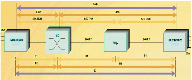
STS-1 Frames
Figure 2 shows the Synchronous Transport Signal level 1 (STS-1) frame structure.
Figure 2 – STS-1 Frame Structure 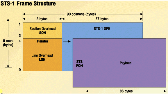
STS-1 SONET Overhead
Figure 3 shows the STS-1 Transport and Path Overhead (SONET Overhead).
Figure 3 – STS-1 Transport and Path Overhead 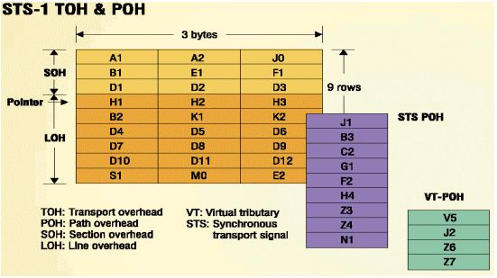
OC-12 Concatenation
Figure 4 looks at OC-12 concatenation.
Figure 4 – OC-12 Concatenation 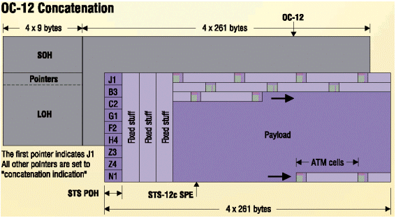
SONET Hierarchy
Figure 5 displays the SONET hierarchy.
Figure 5 – SONET Hierarchy 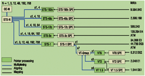
SONET Maintenance Interactions
Figure 6 shows how SONET maintenance interactions appear.
Figure 6 – SONET Maintenance Interactions 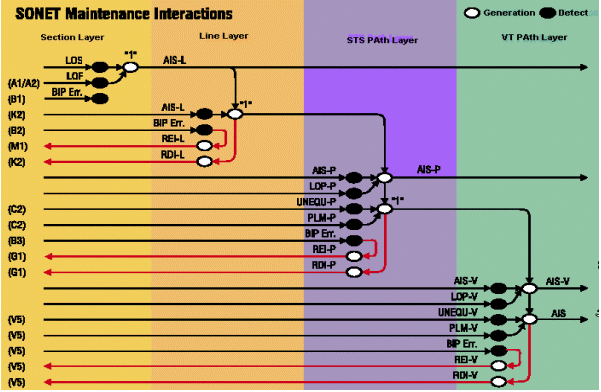
Alarms and Detection Criteria
Table 1 lists what the alarms mean, and their detection criteria.
Table 1 – Meaning of Alarms and their Detection Criteria 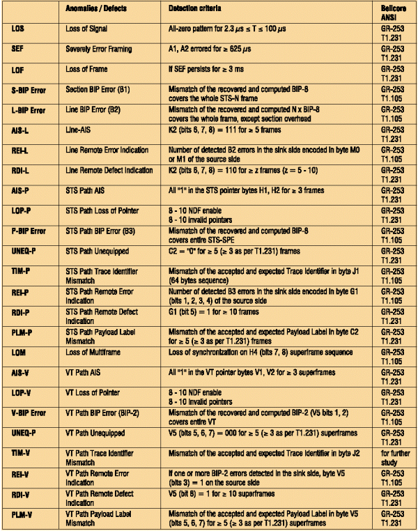
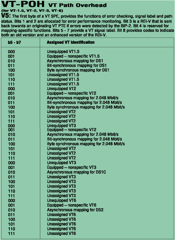
STS-1 SOH, LOH, POH and VT POH Bytes
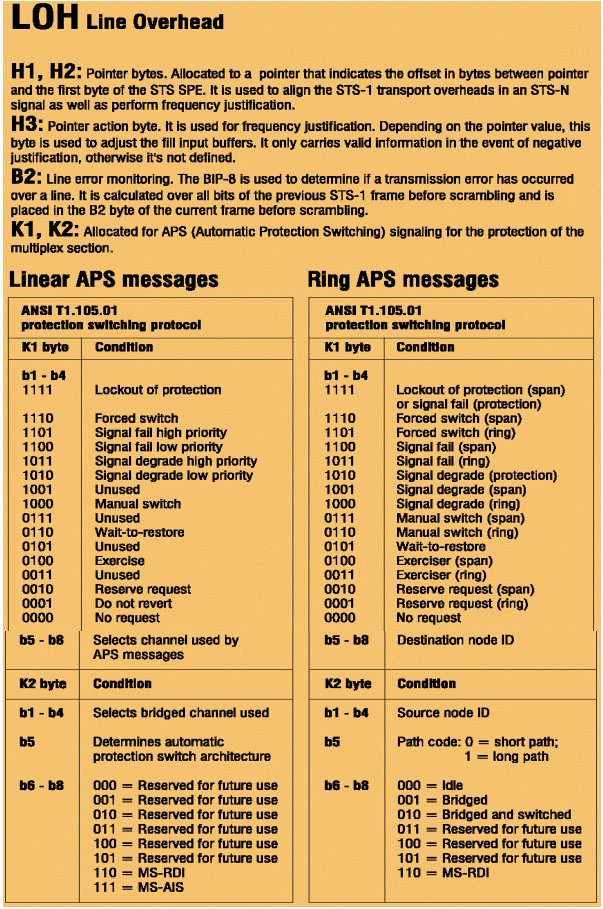
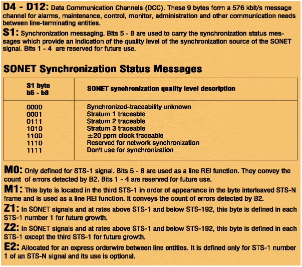
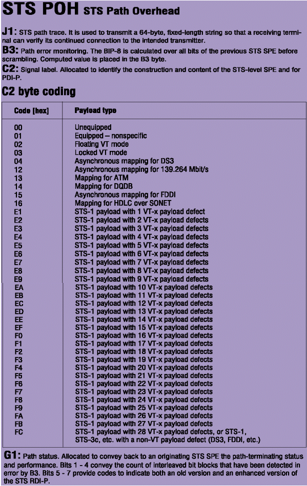
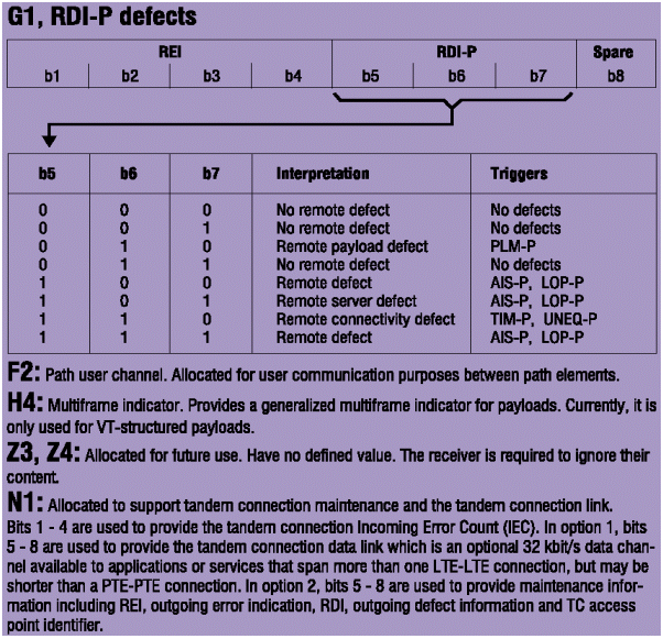
Figure 7 and Figure 8 provide a description of all the bytes from STS-1 SOH, Line OverHead (LOH), Path OverHead (POH) and Virtual Tributary Path OverHead (VT POH).
Figure 7 – SOH Section Overhead 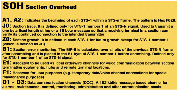
Related Information
Revision History
| Revision | Publish Date | Comments |
|---|---|---|
1.0 |
06-Feb-2005 |
Initial Release |
Contact Cisco
- Open a Support Case

- (Requires a Cisco Service Contract)
 Feedback