Configuring an IPSec Tunnel Between a Cisco Secure PIX Firewall and a Checkpoint NG Firewall
Available Languages
Contents
Introduction
This document demonstrates how to configure an IPsec tunnel with pre-shared keys to communicate between two private networks. In this example, the communicating networks are the 192.168.10.x private network inside the Cisco Secure PIX Firewall and the 10.32.x.x private network inside the CheckpointTM Next Generation (NG) Firewall.
Prerequisites
Requirements
Ensure that you meet these requirements before you attempt this configuration:
-
Traffic from inside the PIX and inside the CheckpointTM NG to the Internet (represented here by the 172.18.124.x networks) should flow before you start this configuration.
-
Users should be familiar with IPsec negotiation. This process can be broken down into five steps, including two Internet Key Exchange (IKE) phases.
-
An IPsec tunnel is initiated by interesting traffic. Traffic is considered interesting when it travels between the IPsec peers.
-
In IKE Phase 1, the IPsec peers negotiate the established IKE security association (SA) policy. Once the peers are authenticated, a secure tunnel is created using Internet Security Association and Key Management Protocol (ISAKMP).
-
In IKE Phase 2, the IPsec peers use the authenticated and secure tunnel to negotiate IPsec SA transforms. The negotiation of the shared policy determines how the IPsec tunnel is established.
-
The IPsec tunnel is created and data is transferred between the IPsec peers based on the IPsec parameters configured in the IPsec transform sets.
-
The IPsec tunnel terminates when the IPsec SAs are deleted or when their lifetime expires.
-
Components Used
The information in this document is based on these software and hardware versions:
-
PIX Software version 6.2.1
-
CheckpointTM NG Firewall
The information in this document was created from the devices in a specific lab environment. All of the devices used in this document started with a cleared (default) configuration. If your network is live, make sure that you understand the potential impact of any command.
Network Diagram
This document uses this network setup:

Conventions
Refer to Cisco Technical Tips Conventions for more information on document conventions.
Configure the PIX
This section presents you with the information to configure the features described in this document.
| PIX Configuration |
|---|
PIX Version 6.2(1) nameif ethernet0 outside security0 nameif ethernet1 inside security100 enable password 8Ry2YjIyt7RRXU24 encrypted passwd 2KFQnbNIdI.2KYOU encrypted hostname PIXRTPVPN domain-name cisco.com fixup protocol ftp 21 fixup protocol http 80 fixup protocol h323 h225 1720 fixup protocol h323 ras 1718-1719 fixup protocol ils 389 fixup protocol rsh 514 fixup protocol rtsp 554 fixup protocol smtp 25 fixup protocol sqlnet 1521 fixup protocol sip 5060 fixup protocol skinny 2000 names !--- Interesting traffic to be encrypted to the Checkpoint™ NG. access-list 101 permit ip 192.168.10.0 255.255.255.0 10.32.0.0 255.255.128.0 !--- Do not perform Network Address Translation (NAT) on traffic to the Checkpoint™ NG. access-list nonat permit ip 192.168.10.0 255.255.255.0 10.32.0.0 255.255.128.0 pager lines 24 interface ethernet0 10baset interface ethernet1 10full mtu outside 1500 mtu inside 1500 ip address outside 172.18.124.158 255.255.255.0 ip address inside 192.168.10.1 255.255.255.0 ip audit info action alarm ip audit attack action alarm pdm history enable arp timeout 14400 global (outside) 1 interface !--- Do not perform NAT on traffic to the Checkpoint™ NG. nat (inside) 0 access-list nonat nat (inside) 1 0.0.0.0 0.0.0.0 0 0 route outside 0.0.0.0 0.0.0.0 172.18.124.1 1 timeout xlate 3:00:00 timeout conn 1:00:00 half-closed 0:10:00 udp 0:02:00 rpc 0:10:00 h323 0:05:00 sip 0:30:00 sip_media 0:02:00 timeout uauth 0:05:00 absolute aaa-server TACACS+ protocol tacacs+ aaa-server RADIUS protocol radius aaa-server LOCAL protocol local no snmp-server location no snmp-server contact snmp-server community public no snmp-server enable traps floodguard enable !--- Permit all inbound IPsec authenticated cipher sessions. sysopt connection permit-ipsec no sysopt route dnat !--- Defines IPsec encryption and authentication algorithms. crypto ipsec transform-set rtptac esp-3des esp-md5-hmac !--- Defines crypto map. crypto map rtprules 10 ipsec-isakmp crypto map rtprules 10 match address 101 crypto map rtprules 10 set peer 172.18.124.157 crypto map rtprules 10 set transform-set rtptac !--- Apply crypto map on the outside interface. crypto map rtprules interface outside isakmp enable outside !--- Defines pre-shared secret used for IKE authentication. isakmp key ******** address 172.18.124.157 netmask 255.255.255.255 !--- Defines ISAKMP policy. isakmp policy 1 authentication pre-share isakmp policy 1 encryption 3des isakmp policy 1 hash md5 isakmp policy 1 group 2 isakmp policy 1 lifetime 86400 telnet timeout 5 ssh timeout 5 terminal width 80 Cryptochecksum:089b038c8e0dbc38d8ce5ca72cf920a5 : end |
Configure the Checkpoint NG
Network objects and rules are defined on the CheckpointTM NG to make up the policy that pertains to the VPN configuration to be set up. This policy is then installed using the CheckpointTM NG Policy Editor to complete the CheckpointTM NG side of the configuration.
-
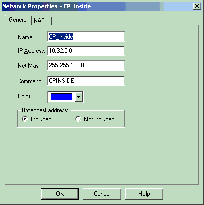
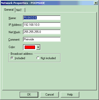
Create the two network objects for the Checkpoint network and PIX Firewall network that encrypt the interesting traffic.
In order to do this, select Manage > Network Objects, then select New > Network. Enter the appropriate network information, then click OK.
These examples show a set up of network objects called CP_Inside (inside network of CheckpointTM NG) and PIXINSIDE (inside network of PIX).
-
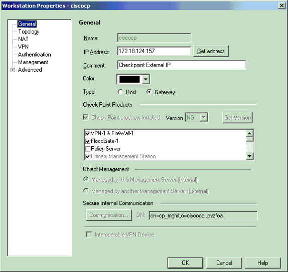
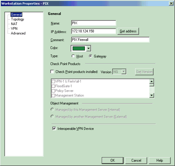
Create workstation objects for the CheckpointTM NG and PIX. In order to do this, select Manage > Network Objects > New > Workstation.
Note that you can use the CheckpointTM NG workstation object created during initial CheckpointTM NG setup. Select the options to set the workstation as Gateway and Interoperable VPN Device, and then click OK.
These examples show a set up of objects called ciscocp (CheckpointTM NG) and PIX (PIX Firewall).
-
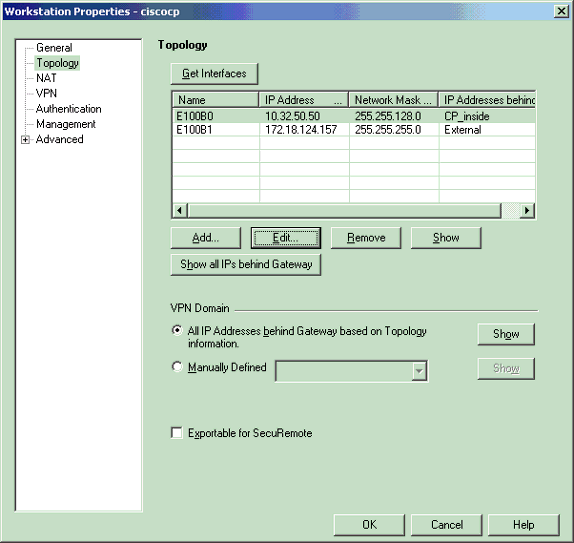
Select Manage > Network objects > Edit to open the Workstation Properties window for the CheckpointTM NG workstation (ciscocp in this example).
Select Topology from the choices on the left side of the window, then select the network to be encrypted. Click Edit to set the interface properties.
-
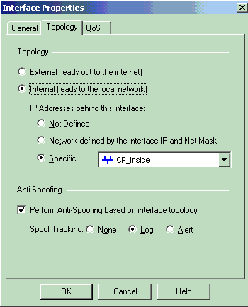
Select the option to designate the workstation as internal, then specify the appropriate IP address. Click OK.
In this configuration, CP_inside is the inside network of the CheckpointTM NG. The topology selections shown here designate the workstation as internal and specify the address as CP_inside.
-
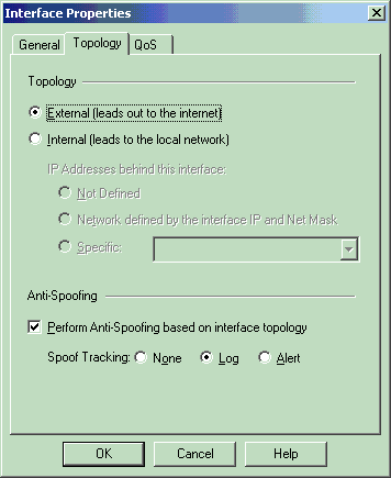
From the Workstation Properties window, select the outside interface on the CheckpointTM NG that leads out to the Internet, then click Edit to set the interface properties. Select the option to designate the topology as external, then click OK.
-
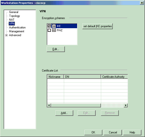
From the Workstation Properties window on the CheckpointTM NG, select VPN from the choices on the left side of the window, then select IKE parameters for encryption and authentication algorithms. Click Edit to configure the IKE properties.
-
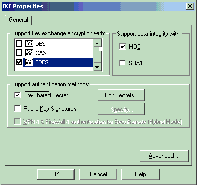
Configure the IKE properties:
-
Select the option for 3DES encryption so that the IKE properties are compatible with the isakmp policy # encryption 3des command.
-
Select the option for MD5 so that the IKE properties are compatible with the crypto isakmp policy # hash md5 command.
-
-
Select the authentication option for Pre-Shared Secrets, then click Edit Secrets to set the pre-shared key as compatible with the PIX command isakmp key key address address netmask netmask . Click Edit to enter your key as shown here and click Set, OK.

-
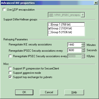
From the IKE properties window, click Advanced... and change these settings:
-
Deselect the option for Support aggressive mode.
-
Select the option for Support key exchange for subnets.
Click OK when you are done.
-
-
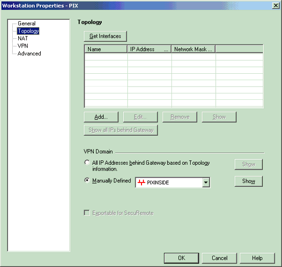
Select Manage > Network objects > Edit to open the Workstation Properties window for the PIX. Select Topology from the choices on the left side of the window to manually define the VPN domain.
In this configuration, PIXINSIDE (inside network of PIX) is defined as the VPN domain.
-
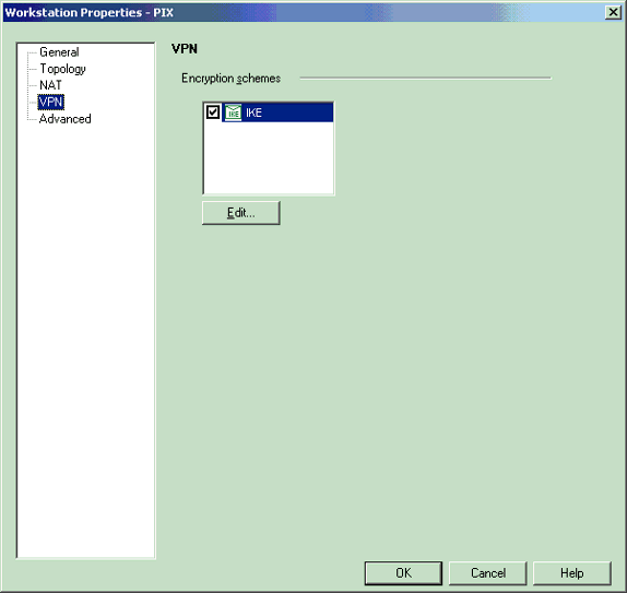
Select VPN from the choices on the left side of the window, then select IKE as the encryption scheme. Click Edit to configure the IKE properties.
-
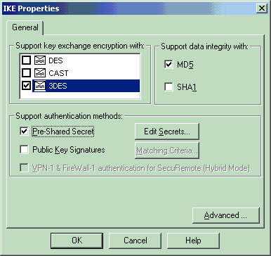
Configure the IKE properties as shown here:
-
Select the option for 3DES encryption so that the IKE properties are compatible with the isakmp policy # encryption 3des command.
-
Select the option for MD5 so that the IKE properties are compatible with the crypto isakmp policy # hash md5 command.
-
-
Select the authentication option for Pre-Shared Secrets, then click Edit Secrets to set the pre-shared key as compatible with the PIX command isakmp key key address address netmask netmask . Click Edit to enter your key, then click Set, OK.

-
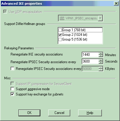
From the IKE properties window, click Advanced... and change these settings.
-
Select the Diffie-Hellman group appropriate for IKE properties.
-
Deselect the option for Support aggressive mode.
-
Select the option for Support key exchange for subnets.
Click OK, OK when you are done.
-
-
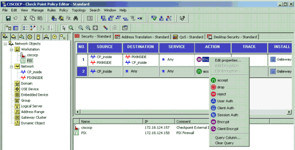
Select Rules > Add Rules > Top to configure the encryption rules for the policy.
In the Policy Editor window, insert a rule with a source of CP_inside (inside network of the Checkpoint TM NG) and PIXINSIDE (inside network of the PIX) on both the source and destination columns. Set values for Service = Any, Action = Encrypt, and Track = Log. When you have added the Encrypt Action section of the rule, right-click Action and select Edit Properties.
-
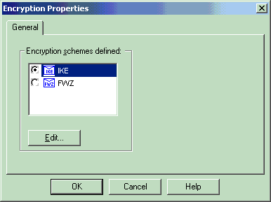
With IKE selected and highlighted, click Edit.
-
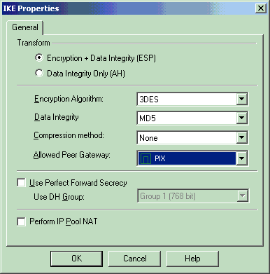
On the IKE Properties window, change the properties to agree with the PIX IPsec transforms in the crypto ipsec transform-set rtptac esp-3des esp-md5-hmac command.
Set the Transform option to Encryption + Data Integrity (ESP), set Encryption Algorithm to 3DES, set Data Integrity to MD5, and set the Allowed Peer Gateway to match the external PIX gateway (called PIX here). Click OK.
-
After you configure the CheckpointTM NG, save the policy and select Policy > Install to enable it.
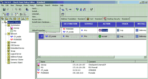
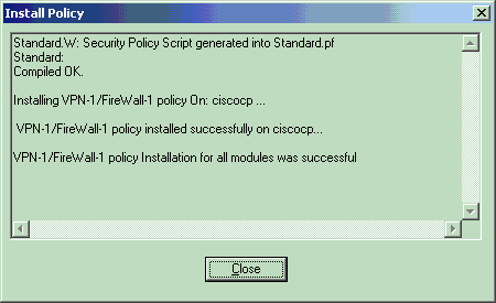
The installation window displays progress notes as the policy is compiled.

When the installation window indicates that the policy installation is complete. Click Close to finish the procedure.
Verify
Verify the PIX Configuration
Use this section to confirm that your configuration works properly.
The Output Interpreter Tool (registered customers only) (OIT) supports certain show commands. Use the OIT to view an analysis of show command output.
Initiate a ping from one of the private networks to the other private network to test communication between the two private networks. In this configuration, a ping was sent from the PIX side (192.168.10.2) to the CheckpointTM NG internal network (10.32.50.51).
-
show crypto isakmp sa—Displays all current IKE SAs at a peer.
show crypto isakmp sa Total : 1 Embryonic : 0 dst src state pending created 172.18.124.157 172.18.124.158 QM_IDLE 0 1 -
show crypto ipsec sa—Displays the settings used by current SAs.
PIX501A#show cry ipsec sa

interface: outside
    Crypto map tag: rtprules, local addr. 172.18.124.158

   local  ident (addr/mask/prot/port): (192.168.10.0/255.255.255.0/0/0)
   remote ident (addr/mask/prot/port): (10.32.0.0/255.255.128.0/0/0)
   current_peer: 172.18.124.157
     PERMIT, flags={origin_is_acl,}
    #pkts encaps: 19, #pkts encrypt: 19, #pkts digest 19
    #pkts decaps: 19, #pkts decrypt: 19, #pkts verify 19
    #pkts compressed: 0, #pkts decompressed: 0
    #pkts not compressed: 0, #pkts compr. failed: 0, #pkts decompress failed: 0
    #send errors 1, #recv errors 0

     local crypto endpt.: 172.18.124.158, remote crypto endpt.: 172.18.124.157
     path mtu 1500, ipsec overhead 56, media mtu 1500
     current outbound spi: 6b15a355

     inbound esp sas:
      spi: 0xced238c7(3469883591)
        transform: esp-3des esp-md5-hmac ,
        in use settings ={Tunnel, }
        slot: 0, conn id: 3, crypto map: rtprules
        sa timing: remaining key lifetime (k/sec): (4607998/27019)
        IV size: 8 bytes
        replay detection support: Y

     inbound ah sas:
     inbound pcp sas:

     outbound esp sas:
      spi: 0x6b15a355(1796580181)
        transform: esp-3des esp-md5-hmac ,
        in use settings ={Tunnel, }
        slot: 0, conn id: 4, crypto map: rtprules
        sa timing: remaining key lifetime (k/sec): (4607998/27019)
        IV size: 8 bytes
        replay detection support: Y


     outbound ah sas:

     outbound pcp sas:
View Tunnel Status on Checkpoint NG
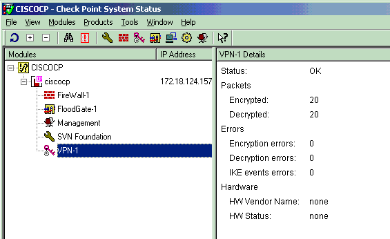
Go to the Policy Editor and select Window > System Status to view the tunnel status.
Troubleshoot
Troubleshoot the PIX Configuration
The Output Interpreter Tool (registered customers only) (OIT) supports certain show commands. Use the OIT to view an analysis of show command output.
Note: Refer to Important Information on Debug Commands before you use debug commands.
Use these commands to enable debugs on the PIX Firewall.
-
debug crypto engine—Displays debug messages about crypto engines, which perform encryption and decryption.
-
debug crypto isakmp—Displays messages about IKE events.
VPN Peer: ISAKMP: Added new peer: ip:172.18.124.157 Total VPN Peers:1
VPN Peer: ISAKMP: Peer ip:172.18.124.157 Ref cnt incremented to:1 Total VPN Peers:1
ISAKMP (0): beginning Main Mode exchange
crypto_isakmp_process_block: src 172.18.124.157, dest 172.18.124.158
OAK_MM exchange
ISAKMP (0): processing SA payload. message ID = 0
ISAKMP (0): Checking ISAKMP transform 1 against priority 1 policy
ISAKMP: encryption 3DES-CBC
ISAKMP: hash MD5
ISAKMP: default group 2
ISAKMP: auth pre-share
ISAKMP: life type in seconds
ISAKMP: life duration (VPI) of 0x0 0x1 0x51 0x80
ISAKMP (0): atts are acceptable. Next payload is 0
ISAKMP (0): SA is doing pre-shared key authentication using id type ID_IPV4_ADDR
return status is IKMP_NO_ERROR
crypto_isakmp_process_block: src 172.18.124.157, dest 172.18.124.158
OAK_MM exchange
ISAKMP (0): processing KE payload. message ID = 0
ISAKMP (0): processing NONCE payload. message ID = 0
ISAKMP (0): ID payload
next-payload : 8
type : 1
protocol : 17
port : 500
length : 8
ISAKMP (0): Total payload length: 12
return status is IKMP_NO_ERROR
crypto_isakmp_process_block: src 172.18.124.157, dest 172.18.124.158
OAK_MM exchange
ISAKMP (0): processing ID payload. message ID = 0
ISAKMP (0): processing HASH payload. message ID = 0
ISAKMP (0): SA has been authenticated
ISAKMP (0): beginning Quick Mode exchange, M-ID of 322868148:133e93b4 IPSEC(key_engine): got a queue event...
IPSEC(spi_response): getting spi 0xced238c7(3469883591) for SA
from 172.18.124.157 to 172.18.124.158 for prot 3
return status is IKMP_NO_ERROR
ISAKMP (0): sending INITIAL_CONTACT notify
ISAKMP (0): sending NOTIFY message 24578 protocol 1
ISAKMP (0): sending INITIAL_CONTACT notify
crypto_isakmp_process_block: src 172.18.124.157, dest 172.18.124.158
OAK_QM exchange
oakley_process_quick_mode:
OAK_QM_IDLE
ISAKMP (0): processing SA payload. message ID = 322868148
ISAKMP : Checking IPSec proposal 1
ISAKMP: transform 1, ESP_3DES
ISAKMP: attributes in transform:
ISAKMP: encaps is 1
ISAKMP: SA life type in seconds
ISAKMP: SA life duration (basic) of 28800
ISAKMP: SA life type in kilobytes
ISAKMP: SA life duration (VPI) of 0x0 0x46 0x50 0x0
ISAKMP: authenticator is HMAC-MD5
ISAKMP (0): atts are acceptable. IPSEC(validate_proposal_request): proposal part #1,
(key eng. msg.) dest= 172.18.124.157, src= 172.18.124.158,
dest_proxy= 10.32.0.0/255.255.128.0/0/0 (type=4),
src_proxy= 192.168.10.0/255.255.255.0/0/0 (type=4),
protocol= ESP, transform= esp-3des esp-md5-hmac ,
lifedur= 0s and 0kb,
spi= 0x0(0), conn_id= 0, keysize= 0, flags= 0x4
ISAKMP (0): processing NONCE payload. message ID = 322868148
ISAKMP (0): processing ID payload. message ID = 322868148
ISAKMP (0): processing ID payload. message ID = 322868148
ISAKMP (0): processing NOTIFY payload 24576 protocol 3
spi 3469883591, message ID = 322868148
ISAKMP (0): processing responder lifetime
ISAKMP (0): processing NOTIFY payload 24576 protocol 3
spi 3469883591, message ID = 322868148
ISAKMP (0): processing responder lifetime
ISAKMP (0): Creating IPSec SAs
inbound SA from 172.18.124.157 to 172.18.124.158 (proxy 10.32.0.0 to 192.168.10.0)
has spi 3469883591 and conn_id 3 and flags 4
lifetime of 28800 seconds
lifetime of 4608000 kilobytes
outbound SA from 172.18.124.158 to 172.18.124.157 (proxy 192.168.10.0 to 10.32.0.0)
has spi 1796580181 and conn_id 4 and flags 4
lifetime of 28800 seconds
lifetime of 4608000 kilobytesIPSEC(key_engine): got a queue event...
IPSEC(initialize_sas): ,
(key eng. msg.) dest= 172.18.124.158, src= 172.18.124.157,
dest_proxy= 192.168.10.0/255.255.255.0/0/0 (type=4),
src_proxy= 10.32.0.0/255.255.128.0/0/0 (type=4),
protocol= ESP, transform= esp-3des esp-md5-hmac ,
lifedur= 28800s and 4608000kb,
spi= 0xced238c7(3469883591), conn_id= 3, keysize= 0, flags= 0x4
IPSEC(initialize_sas): ,
(key eng. msg.) src= 172.18.124.158, dest= 172.18.124.157,
src_proxy= 192.168.10.0/255.255.255.0/0/0 (type=4),
dest_proxy= 10.32.0.0/255.255.128.0/0/0 (type=4),
protocol= ESP, transform= esp-3des esp-md5-hmac ,
lifedur= 28800s and 4608000kb,
spi= 0x6b15a355(1796580181), conn_id= 4, keysize= 0, flags= 0x4
VPN Peer: IPSEC: Peer ip:172.18.124.157 Ref cnt incremented to:2 Total VPN Peers:1
VPN Peer: IPSEC: Peer ip:172.18.124.157 Ref cnt incremented to:3 Total VPN Peers:1
return status is IKMP_NO_ERROR
Network Summarization
When multiple adjacent inside networks are configured in the encryption domain on the Checkpoint, the device might automatically summarize them with regard to interesting traffic. If the crypto access control list (ACL) on the PIX is not configured to match, the tunnel is likely to fail. For example, if the inside networks of 10.0.0.0 /24 and 10.0.1.0 /24 are configured to be included in the tunnel, they can be summarized to 10.0.0.0 /23.
View Checkpoint NG Logs
Select Window > Log Viewer to view the logs.

Related Information
Revision History
| Revision | Publish Date | Comments |
|---|---|---|
1.0 |
12-May-2006 |
Initial Release |
Contact Cisco
- Open a Support Case

- (Requires a Cisco Service Contract)


 Feedback