Lock-and-Key: Dynamic Access Lists
Available Languages
Contents
Introduction
Lock-and-key access allows you to set up dynamic access lists that grant access per user to a specific source/destination host through a user authentication process. User access is allowed through a Cisco IOS® Firewall dynamically, without any compromise in the security restrictions.
Prerequisites
Requirements
There are no specific requirements for this document.
Components Used
This document is not restricted to specific software and hardware versions.
The information presented in this document was created from devices in a specific lab environment. In this case, the lab environment consisted of a 2620 Router running Cisco IOS® Software Release 12.3(1). All of the devices used in this document started with a cleared (default) configuration. If your network is live, make sure that you understand the potential impact of any command.
Conventions
Refer to the Cisco Technical Tips Conventions for more information on document conventions.
Spoofing Considerations
Lock-and-key access allows an external event to place an opening in the Cisco IOS Firewall. After this opening exists, the router is susceptible to source address spoofing. In order to prevent this, provide encryption support using IP encryption with authentication or encryption.
Spoofing is a problem with all existing access lists. Lock-and-key access does not address this problem.
Because lock-and-key access introduces a potential pathway through your network firewall, you need to consider dynamic access. Another host, spoofing your authenticated address, gains access behind the firewall. With dynamic access, there is the possibility that an unauthorized host, spoofing your authenticated address, gains access behind the firewall. Lock-and-key access does not cause the address spoofing problem. The problem is only identified here as a concern to the user.
Performance
Performance is affected in these two situations.
-
Each dynamic access list forces an access list rebuild on the silicon switching engine (SSE). This causes the SSE switching path to slow down momentarily.
-
Dynamic access lists require the idle timeout facility (even if the timeout is left to default). Therefore, dynamic access lists cannot be SSE switched. These entries are handled in the protocol fast-switching path.
Watch the border router configurations. Remote users create access list entries on the border router. The access list grows and shrinks dynamically. Entries are dynamically removed from the list after either the idle-timeout or max-timeout period expires. Large access lists degrade packet switching performance.
When to Use Lock-and-Key Access
Two examples of when you use lock-and-key access are listed here:
-
When you want a remote host to be able to access a host in your internetwork through the Internet. Lock-and-key access limits the access beyond your firewall on an individual host or net basis.
-
When you want a subset of hosts on a network to access a host on a remote network protected by a firewall. With lock-and-key access, you can enable only a desired set of hosts to gain access by having them authenticate through a TACACS+ or RADIUS server.
Lock-and-Key Access Operation
This process describes the lock-and-key access operation.
-
A user opens a Telnet session to a border router configured for lock-and-key access.
-
The Cisco IOS software receives the Telnet packet. It performs a user authentication process. The user must pass authentication before access is allowed. The authentication process is done by the router or a central access server such as a TACACS+ or RADIUS server.
Sample Configuration and Troubleshooting
Network Diagram

Cisco recommends that you use a TACACS+ server for your authentication query process. TACACS+ provides authentication, authorization, and accounting services. It also provides protocol support, protocol specification, and a centralized security database.
You can authenticate the user on the router or with a TACACS+ or RADIUS server.
Note: These commands are global unless otherwise indicated.
On the router, you need a username for the user for local authentication.
username test password test
The presence of login local on the vty lines causes this username to be used.
line vty 0 4
login local
If you do not trust the user to issue the access-enable command, you can do one of two things:
-
Associate the timeout with the user on a per-user basis.
username test autocommand access-enable host
timeout 10
or
-
Force all users that Telnet in to have the same timeout.
line vty 0 4
login local
autocommand access-enable host timeout 10
Note: The 10 in the syntax is the idle timeout of the access list. It is overridden by the absolute timeout in the dynamic access list.
Define an extended access list that is applied when a user (any user) logs into the router and the access-enable command is issued. The maximum absolute time for this "hole" in the filter is set to 15 minutes. After 15 minutes, the hole closes whether or not anyone uses it. The name testlist needs to exist but is not significant. Limit the networks to which the user has access by configuring the source or destination address (here, the user is not limited ).
access-list 120 dynamic testlist timeout 15 permit ip any any
Define the access list needed to block everything except the ability to Telnet into the router (in order to open a hole, the user needs to Telnet to the router). The IP address here is the Ethernet IP address of the router.
access-list 120 permit tcp any host 171.68.117.189 eq telnet
There is an implicit deny all at the end (not entered here).
Apply this access list to the interface on which users come in.
interface ethernet1
       ip access-group 120 in
You are done.
This is what the filter looks like on the router right now:
Router#show access-lists
Extended IP access list 120
    10 Dynamic testlist permit ip any any log
    20 permit tcp any host 171.68.117.189 eq telnet (68 matches)
Users who get access to your internal network are not able to see anything until they Telnet to the router.
Note: The 10 here is the idle timeout of the access list. It is overridden by the absolute timeout in the dynamic access list.
%telnet 2514A
Trying 171.68.117.189 ...
Connected to 2514A.network.com.
Escape character is '^]'.

User Access Verification

Username: test
Password: test

Connection closed by foreign host.
The filter looks like this.
Router#show access-lists
Extended IP access list 120
    10 Dynamic testlist permit ip any any log
       permit ip host 171.68.109.158 any log (time left 394)
    20 permit tcp any host 171.68.117.189 eq telnet (68 matches)
There is a hole in the filter for this one user based on the source IP address. When someone else does this, you see two holes.
Router#show ip access-lists 120
Extended IP access list 120
    10 Dynamic testlist permit ip any any log
       permit ip host 171.68.109.64 any log
       permit ip host 171.68.109.158 any log
    20 permit tcp any host 171.68.117.189 eq telnet (288 matches)
These users are able to have complete IP access to any destination IP address from their source IP address.
Using TACACS+
Configure TACACS+
Configure a TACACS+ server to force authentication and authorization to be done on the TACACS+ server in order to use TACACS+, as this output shows:
aaa new-model
!
!
aaa authentication login default group tacacs+ local
aaa authorization exec default group tacacs+
tacacs-server host 10.48.66.53 key cisco123
Complete these steps to configure TACACS+ on Cisco Secure ACS for Windows:
-
Open a web browser. Enter the address of your ACS server, which is in the form of http://<IP_address or DNS_name>:2002. (This example uses a default port of 2002.) Log in as admin.
-
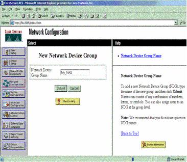
Click Network Configuration. Click Add Entry to create a Network Device Group that contains the network access servers (NAS). Enter a name for the group and click Submit.
-
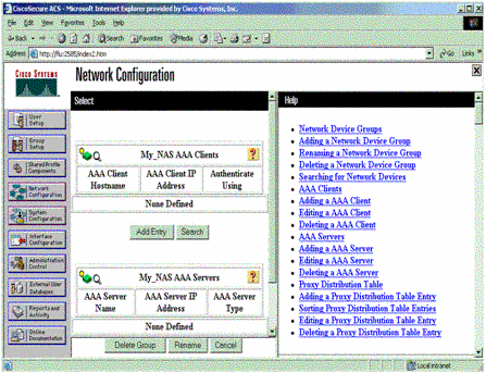
Click Add Entry to add an authentication, authorization, and accounting (AAA) client (NAS).
-
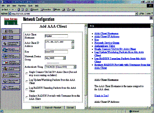
Enter the host name, the IP address, and the key used to encrypt communication between the AAA server and the NAS. Select TACACS+ (Cisco IOS) as the authentication method. When you are finished, click Submit +Restart to apply the changes.
-
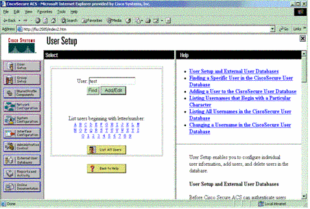
Click User Setup, enter a user ID, and click Add/Edit.
-
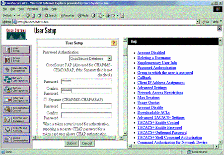
Choose a database to authenticate the user. (In this example, the user is "test" and the internal database of the ACS is used for authentication). Enter a password for user, and confirm the password.
-
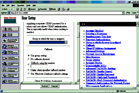
Choose the group to which the user is assigned and check Use group setting. Click Submit.
-
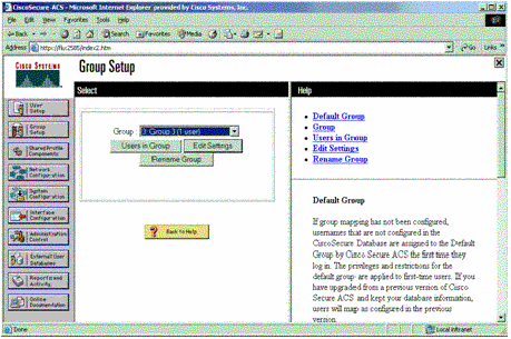
Click Group Setup. Select the group to which the user was assigned in step 7. Click Edit Settings.
-
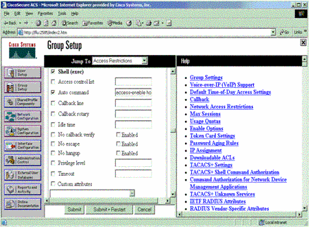
Scroll down to the TACACS+ Settings section. Check the box for Shell exec. Check the box for Auto command. Enter the auto-command to be performed upon successful authorization of the user. (This example uses the access-enable host timeout 10 command.) Click Submit+Restart.
Troubleshoot TACACS+
Use these debug commands on the NAS to troubleshoot TACACS+ problems.
Note: Refer to Important Information on Debug Commands before you use debug commands.
-
debug tacacs authentication—Displays information on the TACACS+ authentication process. Only available in some versions of software. If unavailable, use debug tacacs only.
-
debug tacacs authorization—Displays information on the TACACS+ authorization process. Only available in some versions of software. If unavailable, use debug tacacs only.
-
debug tacacs events—Displays information from the TACACS+ helper process. Only available in some versions of software. If unavailable, use debug tacacs only.
Use these commands to troubleshoot AAA problems:
-
debug aaa authentication—Displays information on AAA/TACACS+ authentication.
-
debug aaa authorization—Displays information on AAA/TACACS+ authorization.
The sample debug output here shows a successful authentication and authorization process on the ACS TACACS+ server.
Router#show debug
General OS:
  TACACS+ events debugging is on
  TACACS+ authentication debugging is on
  TACACS+ authorization debugging is on
  AAA Authentication debugging is on
  AAA Authorization debugging is on
=======================================================
Router#
 AAA/BIND(00000009): Bind i/f
 AAA/AUTHEN/LOGIN (00000009): Pick method list 'default'
 TPLUS: Queuing AAA Authentication request 9 for processing
 TPLUS: processing authentication start request id 9
 TPLUS: Authentication start packet created for 9()
 TPLUS: Using server 10.48.66.53
 TPLUS(00000009)/0/NB_WAIT/82A2E088: Started 5 sec timeout
 TPLUS(00000009)/0/NB_WAIT: socket event 2
 TPLUS(00000009)/0/NB_WAIT: wrote entire 36 bytes request
 TPLUS(00000009)/0/READ: socket event 1
 TPLUS(00000009)/0/READ: Would block while reading
 TPLUS(00000009)/0/READ: socket event 1
 TPLUS(00000009)/0/READ: read entire 12 header bytes
   (expect 16 bytes data)
 TPLUS(00000009)/0/READ: socket event 1
 TPLUS(00000009)/0/READ: read entire 28 bytes response
 TPLUS(00000009)/0/82A2E088: Processing the reply packet
 TPLUS: Received authen response status GET_USER (7)
 TPLUS: Queuing AAA Authentication request 9 for processing
 TPLUS: processing authentication continue request id 9
 TPLUS: Authentication continue packet generated for 9
 TPLUS(00000009)/0/WRITE/8347F3FC: Started 5 sec timeout
 TPLUS(00000009)/0/WRITE: wrote entire 22 bytes request
 TPLUS(00000009)/0/READ: socket event 1
 TPLUS(00000009)/0/READ: read entire 12 header bytes
   (expect 16 bytes data)
 TPLUS(00000009)/0/READ: socket event 1
 TPLUS(00000009)/0/READ: read entire 28 bytes response
 TPLUS(00000009)/0/8347F3FC: Processing the reply packet
 TPLUS: Received authen response status GET_PASSWORD (8)
 TPLUS: Queuing AAA Authentication request 9 for processing
 TPLUS: processing authentication continue request id 9
 TPLUS: Authentication continue packet generated for 9
 TPLUS(00000009)/0/WRITE/8347EE4C: Started 5 sec timeout
 TPLUS(00000009)/0/WRITE: wrote entire 25 bytes request
 TPLUS(00000009)/0/READ: socket event 1
 TPLUS(00000009)/0/READ: read entire 12 header bytes
   (expect 6 bytes data)
 TPLUS(00000009)/0/READ: socket event 1
 TPLUS(00000009)/0/READ: read entire 18 bytes response
 TPLUS(00000009)/0/8347EE4C: Processing the reply packet
 TPLUS: Received authen response status PASS (2)
 AAA/AUTHOR (0x9): Pick method list 'default'
 TPLUS: Queuing AAA Authorization request 9 for processing
 TPLUS: processing authorization request id 9
 TPLUS: Protocol set to None .....Skipping
 TPLUS: Sending AV service=shell
 TPLUS: Sending AV cmd
 TPLUS: Authorization request created for 9(tne-1)
 TPLUS: using previously set server 10.48.66.53
   from group tacacs+
 TPLUS(00000009)/0/NB_WAIT/8347F508: Started 5 sec timeout
 TPLUS(00000009)/0/NB_WAIT: socket event 2
 TPLUS(00000009)/0/NB_WAIT: wrote entire 60 bytes request
 TPLUS(00000009)/0/READ: socket event 1
 TPLUS(00000009)/0/READ: Would block while reading
 TPLUS(00000009)/0/READ: socket event 1
 TPLUS(00000009)/0/READ: read entire 12 header bytes
   (expect 44 bytes data)
 TPLUS(00000009)/0/READ: socket event 1
 TPLUS(00000009)/0/READ: read entire 56 bytes response
 TPLUS(00000009)/0/8347F508: Processing the reply packet
 TPLUS: Processed AV autocmd=access-enable host timeout 10
 TPLUS: received authorization response for 9: PASS
 AAA/AUTHOR/EXEC(00000009): processing AV cmd=
 AAA/AUTHOR/EXEC(00000009): processing AV
   autocmd=access-enable host timeout 10
 AAA/AUTHOR/EXEC(00000009): Authorization successful
Using RADIUS
Configure RADIUS
In order to use RADIUS, configure a RADIUS server to force authentication to be done on the RADIUS server with authorization parameters (the autocommand) to be sent down in vendor-specific attribute 26, as shown here:
aaa new-model
!
!
aaa authentication login default group radius local
aaa authorization exec default group radius local
radius-server host 10.48.66.53 auth-port 1645
   acct-port 1646 key cisco123
Complete these steps to configure RADIUS on Cisco Secure ACS for Windows:
-
Open a web browser and enter the address of your ACS server, which is in the form of http://<IP_address or DNS_name>:2002. (This example uses a default port of 2002.) Log in as admin.
-
Click Network Configuration. Click Add Entry to create a Network Device Group that contains the NAS. Enter a name for the group and click Submit.

-
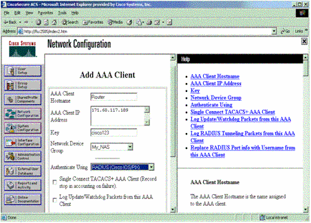
Click Add Entry to add an AAA client (NAS).

-
Enter the host name, the IP address, and the key used to encrypt communication between the AAA server and the NAS. Select RADIUS (Cisco IOS/PIX) as the authentication method. When you are finished, click Submit +Restart to apply the changes.
-
Click User Setup, enter a user ID, and click Add/Edit.

-
Choose a database to authenticate the user. (In this example, the user is "test" and the internal database of the ACS is used for authentication). Enter a password for user, and confirm the password.

-
Choose the group to which the user is assigned and check Use group setting. Click Submit.

-
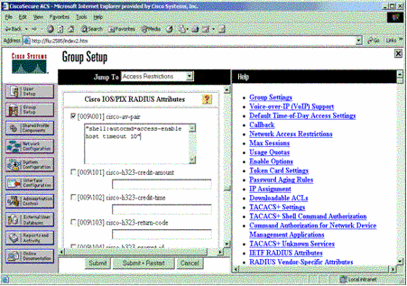
Click Group Setup and select the group to which the user was assigned in the previous step. Click Edit Settings.

-
Scroll down to the Cisco IOS/PIX RADIUS Attributes section. Check the box for cisco-av-pair. Enter the shell command to be performed upon successful authorization of the user. (This example uses shell:autocmd=access-enable host timeout 10.) Click Submit+Restart.
Troubleshoot RADIUS
Use these debug commands on the NAS to troubleshoot RADIUS problems.
Note: Refer to Important Information on Debug Commands before you use debug commands.
-
debug radius—Displays information associated with RADIUS.
Use these commands to troubleshoot AAA problems:
-
debug aaa authentication—Displays information on AAA/TACACS+ authentication.
-
debug aaa authorization—Displays information on AAA/TACACS+ authorization.
The sample debug output here shows a successful authentication and authorization process on the ACS configured for RADIUS.
Router#show debug
General OS:
  AAA Authentication debugging is on
  AAA Authorization debugging is on

Radius protocol debugging is on
Radius packet protocol debugging is on
=======================================================
Router#
 AAA/BIND(00000003): Bind i/f
 AAA/AUTHEN/LOGIN (00000003): Pick method list 'default'
 RADIUS/ENCODE(00000003): ask "Username: "
 RADIUS/ENCODE(00000003): send packet; GET_USER
 RADIUS/ENCODE(00000003): ask "Password: "
 RADIUS/ENCODE(00000003): send packet; GET_PASSWORD
 RADIUS:  AAA Unsupported     [152] 5
 RADIUS:   74 74 79                       [tty]
 RADIUS(00000003): Storing nasport 66 in rad_db
 RADIUS/ENCODE(00000003): dropping service type,
   "radius-server attribute 6 on-for-login-auth" is off
 RADIUS(00000003): Config NAS IP: 0.0.0.0
 RADIUS/ENCODE(00000003): acct_session_id: 1
 RADIUS(00000003): sending
 RADIUS/ENCODE: Best Local IP-Address 172.18.124.1
   for Radius-Server 10.48.66.53
 RADIUS(00000003): Send Access-Request to 10.48.66.53:1645
   id 21645/1, len 77
 RADIUS:  authenticator 5A 95 1F EA A7 94 99 E5 -
   BE B5 07 BD E9 05 5B 5D
 RADIUS:  User-Name           [1]   7   "test"
 RADIUS:  User-Password       [2]   18  *
 RADIUS:  NAS-Port            [5]   6   66
 RADIUS:  NAS-Port-Type       [61]  6   Virtual     [5]
 RADIUS:  Calling-Station-Id  [31]  14  "171.68.109.158"
 RADIUS:  NAS-IP-Address      [4]   6   171.68.117.189
 RADIUS: Received from id 21645/1 10.48.66.53:1645,
   Access-Accept, len 93
 RADIUS:  authenticator 7C 14 7D CB 33 19 97 19 -
   68 4B C3 FC 25 21 47 CD
 RADIUS:  Vendor, Cisco       [26]  51
 RADIUS:   Cisco AVpair       [1]   45
   "shell:autocmd=access-enable host timeout 10"
 RADIUS:  Class               [25]  22
 RADIUS:   43 49 53 43 4F 41 43 53 3A 61 63 31 32 37 63 30
   [CISCOACS:ac127c0]
 RADIUS:   31 2F 36 36                 [1/66]
 RADIUS(00000003): Received from id 21645/1
 AAA/AUTHOR/EXEC(00000003): processing AV
   autocmd=access-enable host timeout 10
 AAA/AUTHOR/EXEC(00000003): Authorization successful
Related Information
Revision History
| Revision | Publish Date | Comments |
|---|---|---|
1.0 |
12-Jul-2006
|
Initial Release |
Contact Cisco
- Open a Support Case

- (Requires a Cisco Service Contract)


 Feedback