Using One DHCP Server for Voice and Data Networks
Available Languages
Contents
Introduction
In an optimized IP Telephony network, IP addresses for telephones and PCs must be set up in different network segments. If Dynamic Host Configuration Protocol (DHCP) is used to assign addresses, then a DHCP server for each network segment is normally needed. However, you can use a single DHCP server to assign both ranges of addresses if you have routers capable of DHCP relay in your IP network. This document explains how and why it is possible to use a single server for both voice and data IP addresses.
Note: The information in this document does not apply in a fully switched network or if you do not have a routing capable device. In such scenarios, there are only two possibilities for assigning different IP addresses to telephones and PCs.You must either have a DHCP server with two network interface cards or have two DHCP servers.
Prerequisites
Requirements
There are no specific requirements for this document.
Components Used
This document is not restricted to specific software and hardware versions.
Conventions
For more information on document conventions, refer to the Cisco Technical Tips Conventions.
Problem
If you install an IP Telephony network, then you must assign IP addresses for your telephones and PCs in different network segments. These address assignments require a DHCP server for each network segment. However, you have only one DHCP server.
Solution
To be able to use your current DHCP server to assign addresses for both VLANs, you must have a Layer 3 (L3) device in the network that can do do the inter-VLAN routing.
The two examples in this document describe how to use one DHCP server to assign both voice and data IP addresses.
The Network Setup
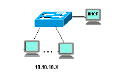
There is a current network with a Cisco Catalyst 6000 or a Catalyst 3524-XL-PWR. In which, VLAN 10 is configured to be the data VLAN used by the PCs and servers. In the same VLAN there is also a DHCP server that runs Windows 2000 to provide addresses in the range 10.10.10.20 to 10.10.10.200. The DHCP server IP address is 10.10.10.2.

To add IP Telephony in this network, plug an IP phone with a PC in the back to the Catalyst port where the PC was connected.
Example of Catalyst 6000 with MSFC
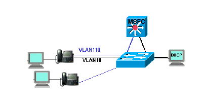
In this scenario, there is a Cisco Catalyst 6000 with a Multilayer Switch Feature Card (MSFC) as the routing capable device.

To allow the PC and telephone to be on the same Catalyst port, you need to configure the auxiliaryVLAN command with the new voice VLAN 110 as shown:
cat6k-access> (enable) set VLAN 110 name 11.1.1.0_voice
cat6k-access> (enable) set VLAN 10 5/1-48
cat6k-access> (enable) set port auxiliaryVLAN 5/1-48 110
To allow the current DHCP server in data VLAN 10 to be used to assign IP addresses to the telephones, follow these steps :
-
Create one interface on the MSFC for each VLAN, data and voice.
-
Configure each interface with a valid address in the VLAN.
-
On the interface VLAN 110, add an ip helper-address command.
This command allows DHCP broadcast packets on the voice VLAN 110 to be sent as unicast packets to the DHCP server in the data VLAN 10.
The configuration on the MSFC should be:
cat6k-msfc(config)#interface vlan10
cat6k-msfc(config-if)#ip address 10.10.10.19
cat6k-msfc(config-if)#<description of data VLAN for PCs and where the DHCP server is located>

cat6k-msfc(config)#interface vlan110
cat6k-msfc(config-if)#ip address 11.1.1.19
cat6k-msfc(config-if)#ip helper-address 10.10.10.2
cat6k-msfc(config-if)#<description VLAN for voice>
The configuration of the Cisco Catalyst 6000 remains unchanged.
-
Configure the DHCP server with a new scope of addresses for the telephones (11.1.1.1.X) in the voice VLAN 110.
If the DHCP server does not have a scope that matches the Relay Agent IP address, then the DHCP request fails. You need to add the option 150 in that scope to provide the TFTP server address to the telephones. For step-by-step instructions on the configuration of the DHCP server for the telephones, refer to Configuring Windows 2000 DHCP Server for Cisco CallManager.
Example of Catalyst 3524-XL with an External Router
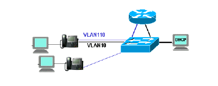
In this scenario, there is a Cisco Catalyst 3524-XL-PWR and an external router as the routing capable device, with one interface in each VLAN.

To allow the PC and telephone to be on the same Catalyst port, configure trunking with the new voice VLAN 110 as shown:
interface FastEthernet0/13
description phone and PC
switchport mode trunk
switchport trunk encapsulation dot1q
switchport voice vlan 110
switchport trunk native vlan 10
Repeat the configuration for all ports on the Catalyst where you have connected a telephone with a PC plugged into the telephone.
To allow the current DHCP server in data VLAN 10 to be used to assign IP addresses to the telephones, follow these steps:
-
Connect two router interfaces to two ports on the Cisco Catalyst 3524-XL, one in VLAN 10 and the other in VLAN 110.
-
On the router side, assign a valid address in each VLAN.
Note: With trunking configured, you can also achieve this with a single port connected from the Catalyst 3524-XL to the router.
-
Issue the ip helper-address command on the router interface that is connected to voice VLAN 110.
This allows DHCP broadcast packets received on the interface to be sent as unicast packets to the DHCP server in data VLAN 10.
The configuration on the router should be as shown:
router(config)#interface FastEthernet0/0
router(config-if)#ip address 10.10.10.19 255.255.255.0

router(config-if)#<description connected to catalyst port 0/10 data VLAN for PCs and DHCP server>

router(config)#interface FastEthernet0/1
router(config-if)#IP address 11.1.1.19 255.255.255.0
router(config-if)#IP helper-address 10.10.10.2
router(config-if)#<description connected to catalyst port 0/11 voice VLAN>
The configuration on the Cisco Catalyst 3524-XL should be:
router(config)interface FastEthernet0/10
router(config-if)#switchport access vlan 10
router(config-if)#<description port on data VLAN going to the router FE0/0>

router(config)interface FastEthernet0/11
router(config-if)#switchport access vlan 110
router(config-if)#<description port on voice VLAN going to the router FE0/1>
-
Configure the DHCP server with a new scope of addresses for the telephones (11.1.1.1.X) in voice VLAN 110.
If the DHCP server does not have a scope that matches the Relay Agent IP address, the DHCP request fails. You need to add the option 150 in that scope to provide the TFTP server address to the telephones. For step-by-step instructions on the configuration of the DHCP server for the telephones, refer to Configuring Windows 2000 DHCP Server for Cisco CallManager.
How the Solution Works
The DHCP server is able to provide addresses from the appropriate scope for both VLANs, based on the use of the Relay Agent field in the DHCP packets. A Relay Agent is the agent that is in charge of the conversion of the broadcast DHCP packets sent by the telephone into unicast packets that are sent to the DHCP server. This agent also converts the unicast DHCP packets sent from the DHCP server into broadcast packets that are sent on the telephone network. In this example, the Relay Agent is the VLAN 110 interface on the MSFC configured with the ip helper-address command.
When the DHCP server receives the DHCP discover message with a current IP address in the Relay Agent field, it uses that address to match the proper scope and assigns the IP address from it. You can see details of this protocol in RFC 3046 ![]() .
.
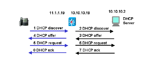
The DHCP packets that are exchanged in this example would be as shown:

The blue lines show the DHCP packets that are sent to and from the IP telephone. These are the only packets that appear if the DHCP server is in the same Ethernet network as the telephones.
The black lines represent the DHCP unicast packets that the Relay Agent transmits to and from the DHCP server.
This table shows the details of the packets for this example. For details about the DHCP protocol and fields, refer to RFC 1541 ![]() .
.
| 1 DHCP Discover | 2 DHCP Discover |
|---|---|
IP Source Address = [0.0.0.0]
IP Destination Address = [255.255.255.255]

DHCP Client IP Address = [0.0.0.0]
DHCP Relay Agent = [0.0.0.0]
Client Hardware Address = 00070EEA5449
Message Type = 1 (DHCP Discover)
Parameter Request List:
...
    150= Unknown Option
... |
IP Source Address = [11.1.1.19]
IP Destination Address =[10.10.10.2]

DHCP Client IP Address = [0.0.0.0]
DHCP Relay Agent = [11.1.1.19]
Client Hardware Address = 00070EEA5449
Message Type = 1 (DHCP Discover)
Parameter Request List:
...
    150= Unknown Option
... |
| 4 DHCP Offer | 3 DHCP Offer |
IP Source Address = [10.10.10.2] IP Destination Address = [255.255.255.255] DHCP Client IP Address = [11.1.1.25] DHCP Relay Agent = [11.1.1.19] Client Hardware Address = 00070EEA5449 Message Type = 2 (DHCP Offer) .... Address Renewel Interval = 216000 (seconds) TFTF Server = "11.1.1.10" ... |
IP Source Address = [10.10.10.2] IP Destination Address = [11.1.1.19] DHCP Client IP Address = [11.1.1.25] DHCP Relay Agent = [11.1.1.19] Client Hardware Address = 00070EEA5449 Message Type = 2 (DHCP Offer) .... Address Renewel Interval = 216000 (seconds) TFTF Server = "11.1.1.10" ... |
| 5 DHCP Request | 6 DHCP Request |
IP Source Address = [0.0.0.0]
IP Destination Address = [255.255.255.255]

DHCP Client IP Address = [0.0.0.0]
DHCP Relay Agent = [0.0.0.0]
Client Hardware Address = 00070EEA5449
Message Type = 3 (DHCP Request)
Request Specific IP Address = [11.1.1.25]
Parameter Request List:
...
    150= Unknown Option
... |
IP Source Address = [11.1.1.19]
IP Destination Address = [10.10.10.2]

DHCP Client IP Address =  [0.0.0.0]
DHCP Relay Agent = [11.1.1.19]
Client Hardware Address = 00070EEA5449
Message Type = 3 (DHCP Request)
Request Specific IP Address = [11.1.1.25]
Parameter Request List:
...
    150= Unknown Option
... |
| 8 DHCP Ack | 7 DHCP Ack |
IP Source Address = [10.10.10.2] IP Destination Address = [255.255.255.255] DHCP Client IP Address = [11.1.1.25] DHCP Relay Agent = [11.1.1.19] Client Hardware Address = 00070EEA5449 Message Type = 5 (DHCP Ack) .... Address Renewel Interval = 216000 (seconds) TFTF Server = "11.1.1.10" ... |
IP Source Address = [10.10.10.2] IP Destination Address = [11.1.1.19] DHCP Client IP Address = [11.1.1.25] DHCP Relay Agent = [11.1.1.19] Client Hardware Address = 00070EEA5449 Message Type = 5 (DHCP Ack) .... Address Renewel Interval = 216000 (seconds) TFTF Server = "11.1.1.10" ... |
 Feedback