LWAPP Traffic Study
Available Languages
Contents
Introduction
The IETF-RFC draft, submitted to the Control And Provisioning of Wireless Access Points (CAPWAP) working group, describes the Light Weight Access Point Protocol (LWAPP) as a protocol developed with the goal to define communication guidelines between Wireless Termination Points (Access Points) and Access Controllers (Wireless LAN Controllers). All LWAPP communications can be classified into one of these two message types:
-
LWAPP Control Channel
-
LWAPP Encapsulated Data
LWAPP can function in either Layer 2 or Layer 3 transport mode. Layer 2 LWAPP communications are encapsulated in Ethernet frames and can be identified with an EtherType value of 0x88BB. Due to its reliability on Ethernet, Layer 2 LWAPP mode of operation is not routable and requires Layer 2 visibility between the WLCs and APs. Layer 2 is considered deprecated and protocol statistics outlined in this traffic study are based on Layer 3 LWAPP transport mode. Layer 3 LWAPP transport mode specifies the exchange of LWAPP messages on the IP network in the form of UDP-encapsulated packets. The LWAPP tunnel is maintained with the IP Address of the WLC (ap-manager) interface and the IP Address of the AP. This traffic study reveals the actual amount of overhead that LWAPP messages present on a network and a baseline of LWAPP operation in a standard install.
Note: The LWAPP specification is discussed in great detail at LWAPP-IETF Draft.
Setup
This document presents statistics related to the operation of LWAPP only and any functionality that is not defined by the protocol specification, such as inter-controller roaming, is outside the scope of this document. Furthermore, the traffic study only covers Layer 3 mode of LWAPP operation.
Figure 1: LWAPP Traffic Study setup 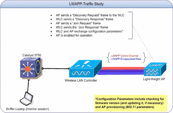
| Interface/Device | IP Address |
|---|---|
| WLC - Management Interface | 192.168.10.102 |
| WLC - ap-manager Interface | 192.168.10.103 |
| Light-Weight AP | 192.168.10.22 |
For the purposes of this traffic study, the setup was created with only one Access Point to establish the initial exchange and configuration changes baselines. More APs were later added to determine the effects of scaling the number of APs on the amount of traffic generated on the wire.
LWAPP Control Channel
The AP uses ephemeral ports when it talks to the WLC. The port numbers used by the WLC, in return, are UDP port 12222 and UDP port 12223 for LWAPP Data and LWAPP Control traffic respectively. An LWAPP control frame is distinguished from an LWAPP data frame by the “C” bit in the header flag field of the LWAPP. If set to 1, it is a control frame.
Initial/One-time Exchanges
LWAPP discovery (Request and Response)
Figure 2: LWAPP Discovery Request and Response packet flow 
The LWAPP Discovery requests, sent by the Access Point, are used in order to determine which WLCs are present in the network.
A discovery request packet is 97 bytes, which includes the 4 byte FCS. A discovery response packet is 106 bytes, which includes the 4 byte FCS.
LWAPP Join (Request and Response)
Figure 3: LWAPP Join Request and Response packet flow 
An LWAPP join request packet is used by the Access Point in order to inform the WLC that it wants to service clients through the controller. The join request phase is also used in order to discover the MTU supported by the transport. The initial join request sent by the Access Point is always padded with a test element of 1596 bytes. Based on how the transport between the AP and the controller is set up, these join request frames can be fragmented as well. If a join response is received for the initial request, the AP forwards frames without any fragmentation. The join response also initiates the heartbeat timer (a 30-second value) which, when it expires, deletes the WLC-AP session. The timer is refreshed upon the receipt of the Echo Request or Acknowledgements.
If the initial join request does not yield any response, the AP sends out another join request with the test element, which brings the total payload to 1500 bytes. If the second join request does not yield a response either, the AP continues to cycle between the large and small packets and eventually times out to start over from the Discovery phase.
Packet sizes for the join request and response messages vary based on the description but the packet exchange captured for the purposes of this traffic-study between the AP and the WLC (ap-manager interface) is 3,000 bytes.
LWAPP config
Figure 4: LWAPP Configure state and AP provisioning packet flow 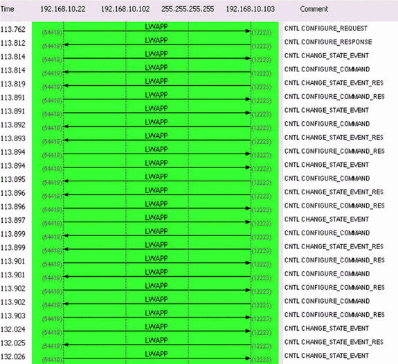
The LWAPP config requests and responses are exchanged between the Access Points and the controllers in order to create, change (update) or delete the services offered by an AP.
In general, a Configure Request message is sent by an AP to send its current configuration to its WLC.
The config request can be sent in two scenarios:
-
In the initial phase when the AP joins a controller and needs to be provisioned with all 802.11 settings that are configured on the controller.
-
In the case of on-demand administrative changes, such as a change to a WLAN parameter
The LWAPP config response message type is sent by the WLC to the AP in order to acknowledge the receipt of the LWAPP config request from the AP. This provides an opportunity for the WLC to override the AP's requested configuration. There are no special message elements contained by such a frame.
The initial exchange between the AP and the WLC (ap-manager interface) is approximately 6,000 bytes and a one-time configuration change averages 360 bytes and involves 2 packets each from the AP and the ap-manager interface of the WLC.
Radio Resource Management (RRM)
Figure 5: Initial RRM packet flow 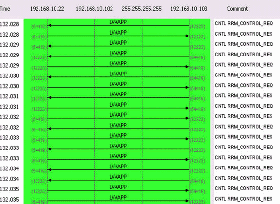
An RRM-related information exchange takes place once the AP is provisioned. A typical exchange between the AP and the WLC (ap-manager interface) is approximately 1400 bytes. In the event of an RRM-related configuration change, there is a four-packet exchange between the AP and the ap-manager interface of the WLC. This exchange averages 375 bytes.
A 20-minute sample capture that includes the discovery, join, configuration, and on-going processes resulted in these traffic statistics on a 100Mbps segment:
Table 1: Initial LWAPP traffic statistics for a single Access Point| Statistic | Value |
|---|---|
| Total Bytes | 84,869 |
| Average Utilization (percent) | 0.001 |
| Average Utilization (kilobits/s) | 0.425 |
| Max Utilization (percent) | 0.004 |
| Max Utilization (kilobits/s) | 5.384 |
Figure 6 is a pictorial representation of the entire process.
Figure 6: Protocol comparison during AP discovery, join and provisioning phase 
Ongoing Exchanges
Heartbeat
The LWAPP architecture provides for a heartbeat timer that is accomplished by a series of Echo Requests and Echo Responses. An AP periodically sends Echo Requests in order to determine the state of the connection between the AP and the WLC. In response, the WLC sends the Echo Response in order to acknowledge the receipt of the Echo Request. The AP, then, resets the heartbeat timer to the EchoInterval. The LWAPP protocol specification draft contains a detailed description of these timers. The system heartbeat, coupled with fallback mechanism, is 4 packets every 30 seconds and is comprised of these packets:
LWAPP ECHO_REQUEST from AP (78 bytes)
LWAPP Echo-Response to AP (64 bytes)
LWAPP PRIMARY_DISCOVERY_REQ from AP (93 bytes)
LWAPP Primary Discovery-Response to AP (97 bytes)
This exchange generates 33 bytes of traffic every 30 seconds.
RRM Measurements
There are two ongoing RRM exchanges. The first one, at every 60-second interval, is the load and signal measurement and consists of 4 packets. This exchange always adds up to 396 bytes:
LWAPP RRM_DATA_REQ from AP (107 bytes)
LWAPP Airewave-Director-Data Response to AP (64 bytes)
LWAPP RRM_DATA_REQ from AP (161 bytes)
LWAPP Airewave-Director-Data Response to AP (64 bytes)
The second sequence of packets is the noise measurement that includes a statistics information request and response sequence. It is done every 180 seconds. This short exchange of packets averages approximately 2,660 bytes and typically lasts 0.01 seconds. It consists of these packets:
LWAPP RRM_DATA_REQ from AP
LWAPP Airewave-Director-Data Response to AP
LWAPP RRM_DATA_REQ from AP
LWAPP Airewave-Director-Data Response to AP
LWAPP RRM_DATA_REQ from AP
LWAPP Airewave-Director-Data Response to AP
LWAPP RRM_DATA_REQ from AP
LWAPP Airewave-Director-Data Response to AP

LWAPP STATISTICS_INFO from AP
LWAPP Statistics-Info Response to AP

LWAPP RRM_DATA_REQ from AP
LWAPP Airewave-Director-Data Response to AP
LWAPP RRM_DATA_REQ from AP
LWAPP Airewave-Director-Data Response to AP
LWAPP RRM_DATA_REQ from AP 00:14:1b:59:41:80
LWAPP Airewave-Director-Data Response to AP
LWAPP RRM_DATA_REQ from AP
LWAPP Airewave-Director-Data Response to AP

LWAPP STATISTICS_INFO from AP
LWAPP Statistics-Info Response to AP
Rogue Measurements
Rogue measurements are done as a part of the scanning mechanism and included in the RRM exchange every 180 seconds. Refer to Radio Resource Management under Unified Wireless Networks for more information.
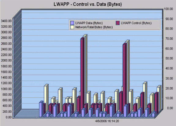
The 20-minute sample capture resulted in the following values for ongoing packet exchanges on a 100Mbps segment:
Table 2: Ongoing LWAPP traffic statistics for a single Access Point| Statistic | Value |
|---|---|
| Total Bytes | 45,805 |
| Average Utilization (percent) | < 0.001 |
| Average Utilization (kilobits/s) | 0.35 |
| Max Utilization (percent) | < 0.001 |
| Max Utilization (kilobits/s) | 0.002 |
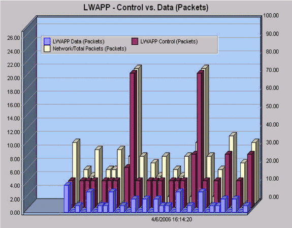
The statistics and exchanges in Table 2 are depicted in these images:
Figure 7: A 20-minute sample of protocol comparison while the AP is in normal operation 
LWAPP Data
Frame Padding
The LWAPP data frame header adds 6 bytes to the existing 802.11 packets. This header is added before the encapsulated 802.11 frame and includes the following:
Light Weight Access Point Protocol  [0-40]
  Flags:                %00000000  [42-48]
                        00.. .... Version: 0
                        ..00 0... Radio ID: 0
                        .... .0.. C Bit - Data message  [0-29]
                        .... ..0. F Bit - Fragmented packet  [0-34]
                        .... ...0 L Bit - Last fragment  [0-30]

  Fragment ID:          0x00  [43-55]
  Length:               74  [44-52]
  Rec Sig Strngth Indic:183  dBm  [46-77]
  Signal to Noise Ratio:25  dB  [47-76]
Fragmentation
Since LWAPP frames can be fragmented, a Fragment ID field is included. The total packet size can be determined if you add the original frame and the IP Fragment. It is important to note that the IP Fragment is not encapsulated in any LWAPP headers.
Conclusion
As evident by the findings in this traffic study, the operation of LWAPP does not introduce heavy bandwidth requirements on the infrastructure, and in most typical deployments, there is no need to add extra capacity to the infrastructure in order to accommodate Cisco Unified Wireless Architecture. As a summary of the traffic study, these quick facts about the operation of LWAPP can be kept in mind:
-
Although latency is an important consideration, this traffic-study presents throughput considerations only. As a general guideline, the AP-to-WLC link must not exceed 100ms round-trip latency.
-
There are two separate channels for the operation of LWAPP:
-
LWAPP Data
-
LWAPP Control traffic
-
-
LWAPP operation is broken down into two broad categories:
-
one-time exchanges
-
on-going exchanges
-
-
A 20 minute sample that includes initial exchanges results in an average utilization statistic of 0.001 percent.
-
A 20 minute sample of on-going exchanges results in a maximum utilization statistic of 0.35 kilobits/second.
-
The LWAPP Data channel adds a header of 6 bytes to each 802.11 data packet. There is no additional overhead for IP Fragments.
-
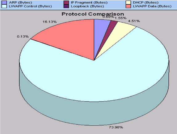
An hour-long sample presents this break-up of protocols and their respective percentages:
Related Information
Contact Cisco
- Open a Support Case

- (Requires a Cisco Service Contract)
 Feedback